Navman 8120/8084 Installation and Operation Manual w w w . n a v m a n .
IMPORTANT SAFETY INFORMATION Please read carefully before installation and use. DANGER This is the safety alert symbol. It is used to alert you to potential personal injury hazards, Obey all safety messages that follow this symbol to avoid possible injury or death.
Contents 1 Introduction .............................................................................................................................................................................7 1-1 Overview . . . . . . . . . . . . . . . . . . . . . . . . . . . . . . . . . . . . . . . . . . . . . . . . . . . . . . . . . . . . . . . . . . . . . . . . . . . . . . . . . . . . . . . . . . . . . 8 1-2 Cleaning and maintenance . . . . . . . . . . . . . . . . . . . . . . . . . . . . . . . . . . . . . . . . . .
10 Sonar fishfinding: Windows ...................................................................................................................................................44 10-1 Sonar history window - no split . . . . . . . . . . . . . . . . . . . . . . . . . . . . . . . . . . . . . . . . . . . . . . . . . . . . . . . . . . . . . . . . . . . .44 10-2 Sonar Zoom and Full Screen Zoom displays . . . . . . . . . . . . . . . . . . . . . . . . . . . . . . . . . . . . . . . . . . . . . . . . . . . . . . . .
19 Setting up the 8120/8084 .......................................................................................................................................................72 19-1 Setup > System . . . . . . . . . . . . . . . . . . . . . . . . . . . . . . . . . . . . . . . . . . . . . . . . . . . . . . . . . . . . . . . . . . . . . . . . . . . . . . . . . . . . 73 19-2 Setup > Chart . . . . . . . . . . . . . . . . . . . . . . . . . . . . . . . . . . . . . . . . . . . . . . . . . . . . . . . . . . . .
Warning It is your sole responsibility to install and use the instrument and transducer(s) in a manner that will not cause accidents, personal injury or property damage. Always observe safe boating practices. The choice, location, and installation of transducers and other components of the system are critical to the performance of the system as intended. If in doubt, consult your NAVMAN dealer.
1 Introduction Quick reference to the built-in and optional features: Feature Type See General How to use the keys and windows 2 Troubleshooting Appendix B Simulate mode 2-6 Glossary of special names Appendix C Specifications Appendix A MOB Man overboard key 2-4 Navigation Overview of how to navigate 3-1 Finding the boat’s position on the chart 3-2 Navigate to any point or to a waypoint 3-1 Navigate along a route 3-1 Projected course: An estimate of progress 3-4 Tracks: records o
Radar Overview of the radar 18 Radar The radar window explained 18-1 Radar Change the radar operation mode 18-2 Radar Change the radar rotation or motion mode 18-6, 18-7 Radar Optimize the quality of the radar window 18-9 Radar Find range and bearing with VRM/EBL 18-10 Radar Set up the radar guard zones 18-12 Radar 1-1 Overview The NAVMAN 8120/8084 is a rugged, highly integrated marine chartplotter and fishfinder. It is easy to use and has a high resolution color display.
1-3 Plug-in cards The 8120/8084 can use two kinds of C-MAP™ SD-Card plug-in cards: 1. Chart cards have chart details required for navigating in a particular region. When you insert a chart card, the extra details automatically appear on the Chart window. You can plug in up to two chart cards at once. If the chart shows a region not covered by a chart card, then it displays a simplified built-in world chart. 2. User cards store navigation data.
1-4 Removing and replacing the display unit If the 8120/8084 is bracket mounted then it can easily be removed for security. Removing the display unit: 1 Turn the 8120/8084 off (see section 2-2) and put the dust cover on. 2 Loosen the knobs on the mounting bracket and lift the unit off the bracket. 3 Unplug the connectors from the 8120/8084; turn each locking collar anticlockwise until you can pull the plug out. 4 Store the 8120/8084 in a dry clean place.
2 Basic Operation Overview of the 8120 keys q 1 5 2 6 4 3 7 8 9 10 ESC – Go back to an earlier menu or window. In chart mode centers chart at boat’s position. w DISPLAY – This is a powerful key that allows you to setup the display the way you want. Main displays can be saved as favorite displays for easy access from the key. e MENU – Show a menu of the options for the current active window. r ENTER – Start an action or accept a change. t / – Changes the range on a window eg.
Overview of the 8084 keys q 1 2 6 5 3 4 7 – Go back to an earlier menu or window. In chart mode centers chart at boat’s position. w DISPLAY – This is a powerful key that allows you to setup the display the way you want. Main displays can be saved as favorite displays for easy access from the key. e MENU – Show a menu of the options for the current active window. The setup menu can be opened by pressing MENU twice. r ENTER – Start an action or accept a change. t / – Changes the range on a window eg.
2-1 Using the keys In this manual: Press means to push the key for less than a second. Hold means to hold the key down. The internal beeper beeps when a key is pressed (to adjust the beep volume, see section 19-1). Using the menus Operate the Instrument by selecting items from menus. Items can be submenus, commands or data. Selecting a submenu A after a menu item indicates a submenu, for example Chart . Press or to move the highlight to the submenu, then press ENTER .
2-2 Turning on and off / auto power Auto power Turning on manually If the Instrument is not wired for auto power, press to turn the unit on. If necessary, adjust the display to be easy to read (see section 2-3). ! WARNING If the Instrument is not wired for auto power then the Instrument does not record engine hours and will not record fuel consumption if not powered (see section 18-4).
2-4 Man overboard (MOB) The MOB feature saves the boat’s position and then navigates back to this point. ! WARNING MOB will not work if the Instrument does not have a GPS fix. 1 Press The Instrument stores the boat’s position as a waypoint called MOB. 2 The Instrument changes to the chart window, with the MOB waypoint at the centre of the chart. The chart zooms in for accurate navigation.
2-6 Simulate mode In Simulate mode, the Instrument ignores data from the GPS antenna and other transducers and sensors and the Instrument generates this data itself. Otherwise, the Instrument functions normally. There are two simulate modes: • Normal: Allows a user to become familiar with the Instrument off the water. • Demo: Simulates a boat moving along a route and automatically displays different Instrument functions. To start and stop Simulate mode, and for more information, see section 19-16.
To show one of the other windows full-screen, press window. DISPLAY , select More... and select the Press ESC to return from one of these windows to the previous window.
2-7-1 Multi window displays The 8120/8084 can show up to four windows at once, for example Chart, Sonar, Gauges and Video: Adding a window to the display Press DISPLAY , select Add window and select a window to add. The 8120/8084 automatically rearranges the display to show the new window. Changing window size 1 Press DISPLAY and select Split ratio. 2 Press or to change the width of the windows. If the 8120/8084 is displaying three or four windows, press or to change the height of the windows.
2-7-2 Favorite displays The 8120/8084 has a list of commonly used displays, called favorite displays. There can be up to six favorite displays. Each display can have one or more windows plus a data header (see section 2-7-3) and a compass (see section 2-7-4). Set up favorite displays for common situations, for example navigating along a route, travelling in a harbour, fishing. Selecting a favorite display To select another favorite, press one or more times.
2-7-3 Data header The displays can show data at the top, called the data header. When you select a window from the display menu (see section 2-7) the 8120/8084 displays an appropriate data header for the window. Each favorite display (see section 2-7-2) has its own data header. When you press to recall a favorite display, the 8120/8084 recalls the favorite displays data header. Setting the data header for a display 1 Press DISPLAY and select Data header. 2 To turn the data header on or off: i Select Data.
3 Navigation: Chart The chart window shows the chart, the boat’s position course and navigation data. 3-1 Introduction to navigating The Instrument has two ways of navigating, going straight to a point or following a route. 3-1-1 Navigating to a point When the Instrument is navigating to a point, the chart and highway windows show navigation data: A The boat position . B The destination point marked with a circle. C The boat’s plotted course to the destination.
Going to a point on the chart 1 Switch to a chart window. 2 Move the cursor to the destination point: either use the cursor keys or use Find (see section 3-2-5). 3 Press MENU and select Goto cursor. ! WARNING Make sure the course does not pass over land or dangerous waters. Navigating The Instrument navigates to the point as described in section 3-1-1. Cancelling navigating Go to a Chart window, press MENU and select Cancel goto. Tip: Before starting, create waypoints at points of interest.
3-2 Chart window To go to the Chart window: • Press DISPLAY and select Chart A typical chart window shows: A B K C F D I F J E G H A Data header. To turn the data off or on or to change what data is displayed (see section 2-7-3) B Compass (see section 2-7-4) C Chart scale (see section 3-2-3) D Boat position (see section 3-2-1) E Boat track (see section 3-5) F Boat course and CDI lines (see Appendix C, CDI).
3-2-1 Chart modes The Chart has two modes: Centre on boat mode To switch to centre on boat mode in the chart window, press ESC . The boat is at the centre of the chart. As the boat moves through the water, the chart automatically scrolls to keep the boat in the centre of the chart. The cursor (see below) is turned off. Cursor mode The keys and are called cursor keys. To switch to cursor mode in the chart window, hold down a cursor key.
ii Select other items or press ESC to return to the chart. To see stored information about nearby symbols press MENU and select Chart info. Then follow step 3 above. 3-2-5 Finding a chart symbol To find and display a chart symbol: 1 Press MENU and select Find. 2 Select the type of symbol: Waypoints, Routes, Ports by name, Ports & services, or Tide stations. 3 For Ports & services: select the type of service to find.
3-4 Projected course If Projected course is turned on, then the Instrument will display the projected position based on the course over ground (COG), speed and a specified time. To turn Projected course on and off and to set the time, see section 19-2. A Projected position B Boat’s projected course C Boat position A B C 3-5 Tracks and tracking Tracking records the boat’s position to memory at regular intervals, which can be: Time intervals. Or distance intervals.
4 Video window The video window shows a picture from a video device, such as a camera. The video window requires a video device to be installed. To select the video window, press DISPLAY and select Video. Adjusting the video picture colour 1 Press MENU . 2 Press or to highlight a control, then press or to adjust the control. 3 To return the colors to their default settings, select Restore defaults. 4 Press ESC .
5 Navigation: Highway window A B C E D F D G The highway window has a bird’s eye view of the boat’s course to a destination: To go to the Highway window, press DISPLAY , select More, then select Highway. The highway window shows: A Optional data header (see section 2-7-3) B Optional compass (see section 2-7-4) C Destination waypoint D Boat’s plotted course to destination E CDI lines, parallel to the boat’s plotted course (see Appendix C, Navigation data, CDI).
6-1 Waypoints window To go to the waypoints window, press DISPLAY , select More, then select Waypoints. The waypoints window is a list of the waypoints that have been entered, each with waypoint symbol, name, latitude and longitude, distance and bearing from the boat, type and display option. If there are more waypoints than will fit on the window, press or to scroll up or down a page at a time. 6-2 Managing waypoints ! WARNING Do not create a navigation waypoint on land or in dangerous water.
Editing a waypoint from the waypoints window 1 In the waypoints window, press or to highlight the waypoint to edit. Press MENU and select Edit. 2 Change the waypoint data (see section 6-2-7). 6-2-4 Displaying a waypoint on the chart This goes to the chart window, and shows the selected waypoint at the centre of the window. 1 In the waypoints window, press or to highlight the waypoint to display. Press MENU and select Display. Or, in the Chart window, press MENU , select Find, then select Waypoints.
7 Navigation: Routes A route is a list of waypoints that the boat can navigate along. Routes can be created, changed and deleted. The Instrument can have up to 25 routes. Each route can have up to 50 waypoints. A route can: Start and stop at the same waypoint . Include waypoints more than once. The Instrument can navigate along a route in either direction. Waypoints on the route can be skipped.
1 In the chart window, press MENU and select New route. 2 The route is given a default name: i Change the name if necessary. ii Select OK. 3 To enter the legs of the route: i Move the cursor to the start of the route and press ENTER . ii A waypoint is created with a default name. To save this waypoint press ENTER , to edit the waypoint refer to 6-2-3 iii Press ENTER a dotted leg line is displayed from the cursor to the previous waypoint iv Move the cursor to the end of the first leg and press ENTER .
5 To remove a waypoint from the route: i Select the waypoint to remove. ii Press MENU and select Remove. 6 Repeat this process until the route is finished. 7 Press ESC . 8 Display the route on the chart (see section 6-2-3) and check that the route does not cross land or dangerous water. 7-2-2 Editing a route Editing a route from the chart 1 In the routes window, select the route to edit. Press MENU and select Edit on chart.
8 Satellites GPS worldwide navigation The US Government operates the GPS system. Twenty-four satellites orbit the earth and broadcast position and time signals. The positions of these satellites are constantly changing. The GPS receiver analyses the signals from the closest satellites and calculates exactly where it is on earth. This is called the GPS position. The accuracy of the GPS position is typically better than 10 m (33 ft) for 95% of the time.
8-1 Satellite window The satellite window has information about the GPS satellites and GPS position. To go to the satellite window, press DISPLAY , select More, then select Satellite. The satellite window shows: A B E C G D F A Status of GPS antenna, for example Acquiring, GPS fix, No GPS. If the unit is in Simulate mode it displays Simulate (see section 2-6). B Time and date from GPS satellites.
The most recent echo appears on the extreme right of the window, with the older echoes being scrolled towards the left, eventually disappearing off the window. The scroll speed depends upon the water depth and scroll speed setting. See sections 19-3 and section 9-2, for more information.
The scroll speed can be set by the user to display either a longer history with less fish information or a shorter history with more fish details (see section 19-3). If the boat is anchored, the echoes all come from the same area of bottom. This produces a flat bottom trace on the window. The screen shot shows a typical sonar window with the Fish symbols turned Off. The sonar pulse generated by the Instrument transducer travels down through the water, spreading outwards in a cone shape.
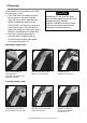
Shadows are created around areas where the ultrasonic beam cannot ‘see’. These areas include hollows on the bottom or beside rocks and ledges, where the strong echoes returned off the rocks obscure the weak echoes of the fish and may also create a double bottom trace. See following for an example of the sonar window in such an environment. A double bottom trace is shown on the window. When looking for fish with the wide angled 50 kHz frequency, be aware of increased shadows.
The 200 kHz frequency generates a higher definition pulse which produces little shadow and returns excellent detail over a small area of bottom. Therefore, it gives excellent bottom discrimination capability and is particularly good at showing individual fish, including bottom dwellers. When to use 50 kHz The 50 kHz frequency is particularly suitable for use in deep water, typically greater than 500 ft (150 m).
Comparison of the same fish scenario displayed at different frequencies: 1 minute ago 30 seconds ago 50 kHz display 200 kHz display 200/50 Khz display Mixed display 40 NAVMAN 8120/8084 Installation and Operation Manual Now
9-4 Fish detection and display Where to find fish Underwater features like reefs, wrecks and rocky outcrops attract fish. Use the 50 kHz or 50/200 kHz frequency window to find these features, then look for fish by passing over the feature slowly several times using the Zoom window (see section 9-2). If there is a current, the fish will often be found downstream of the feature. When fishing with the Instrument with the Fish symbols Off, a weak fuzzy band may appear between the bottom trace and surface.
23 Fun fish symbol Normal fish symbol Fun symbol + depth Fish arch + depth 9-5 Range Range is the vertical depth displayed on the Instrument sonar window. For example, if the range is 100 m, then the sonar window shows depths between 0 and 100 m. The range is displayed at the bottom, right corner of a sonar window. The Instrument has two range modes: Auto: The Instrument adjusts the range automatically so that the bottom of the water is always shown at the bottom of the window.
9-6 Gain and threshold Gain and threshold settings control the amount of detail displayed on a sonar window: Gain: The gain of the sonar receiver. The gain should be high to display good detail, but if the gain is too high then information from the strong bottom signal is lost and false echoes might be displayed. There is a separate gain setting for each sonar frequency, 50 kHz and 200 kHz. Threshold: Return echoes less than the threshold are ignored.
10 Sonar fishfinding: Windows To show the Sonar window, press DISPLAY , then select Sonar. There are five kinds of sonar window. To use a window, press MENU , select Sonar splits, then select the type of window to use: No split: Sonar history window at a single or mixed frequency (see section 10-1).
10-1-1 Extended history mode To review an old sonar echo, use and to move back and forward through the sonar history. The time since the echoes shown on the screen were recorded is displayed at the bottom of the screen. Press ESC to return to the most recent echo. The digital depth shown is always the current depth, even in extended history mode. The History Position Bar indicates the age of the most resent echo on the screen, and the position of the current screen in the recorded history.
10-3 Sonar Bottom window A B A Zoomed bottom signal B Sonar history The window shows the sonar history on the right and the bottom signal as a flat trace in the centre of the zoom section on the left. The flat trace make it easy to compare the echo strengths shown in the bottom signals. This can help to identify the type of bottom and objects close to the bottom. The zoom bar on the far right shows the area of the history that is magnified in the zoom section: • Use the or keys to adjust the zoom range.
10-5 Sonar A-Scope window D E A B C The window shows the sonar history on the left and the A-Scope window on the right. The A-Scope shows: A, B, C, The strengths of echoes being received now from different depths - the longer the horizontal line the stronger the signal: A Unwanted noise echoes.
11 Gauges window The Gauges window shows boat data, such as water speed, as analog gauges. To select the Gauges window, press DISPLAY , select More, then select Gauges. Before using the Gauges window, set Speed range, Max RPM and Max fuel flow (see section 19-13). Selecting a Gauges layout The Gauges window can show one of four gauge layouts. To select a layout from the Gauges window, press MENU , select Layout and select a layout.
13 Fuel functions and display The Fuel functions require optional petrol/gasoline, diesel or SmartCraft fuel sensors to be installed and set up. 13-1 What the fuel computer does Each engine has a flow sensor installed to measure the engine’s fuel flow. The 8120/8084 use these flows, together with boat speed and engine RPM if available to estimate the fuel remaining in the tank(s), fuel used, range and fuel economy. This data is displayed on the fuel display (see section 13-2).
Remaining The fuel remaining in the tank(s) is shown as a vertical gauge on the right of the display. The height of the yellow bar(s) show how much fuel remains in the tank(s). If you have set a low fuel alarm (see section 13-4), a red bar shows the level at which the alarm will trigger. If there are two tanks, the left bar shows the port tank, the right bar shows the starboard tank. Used The fuel used during a trip. On a multi-engine boat, the data for the port engine is on the left of the display.
C When you remove fuel 1. Before removing fuel, go to the Fuel display, press MENU and select Set remaining. 2. On a multi-tank boat, select the tank that you are removing fuel from. 3. Write down the value of Remaining for the tank; this is the amount of fuel originally in the tank. 4. Remove fuel from the tank and write down how much fuel you remove. 5. Subtract the amount of fuel you removed from the amount of fuel originally in the tank to calculate the amount of fuel now in the tank. 6.
13-5-2 Water speed and ground speed A paddlewheel sensor and a pitot sensor measure water speed, the boat speed through the water. A GPS measures ground speed, the boat speed over the bottom of the water. If there is a current, then these speeds will be different, and the log, trip log, economy and range will be different, as shown below. Water speed is better for measuring the boat’s potential performance, Ground speed is better for going to a destination because it takes currents into account.
13-6 Fuel consumption curves A fuel consumption curve shows fuel consumption (fuel used per unit of distance travelled) and boat speed as a function of engine RPM. Fuel consumption curves require engine RPM, which requires SmartCraft or diesel sensors to be installed. Fuel consumption curves are powerful tools for assessing boat performance in different conditions and for helping you to run at the most economical speed for the conditions.
13-6-2 Managing fuel consumption curves Renaming a curve 1 Press MENU twice, then select Fuel. 2 Select Fuel consumption curve. Select Name and select the name of the curve to rename. 3 Select Rename and press ENTER . Change the name. 13-6-3 Using fuel consumption curves Deleting a curve 1 Press MENU twice, then select Fuel. 2 Select Fuel consumption curve. Select Name and select the name of the curve to delete. 3 Select Delete.
13-7 Calibration Calibrate petrol/gasoline fuel flow sensors during installation, or if the fuel readings seem inaccurate and the other troubleshooting suggestions do not help (see Appendix B troubleshooting). Note SmartCraft fuel sensors and NAVMAN diesel sensors are factory calibrated and should never need recalibrating. On a multi engine boat, calibrate each engine’s sensor. This can be done at the same time with a portable tank for each engine or at different times using one portable tank.
14 Tides window The tides window is available on Chart cards. The tides window shows tide information at a tide station for the selected date. 1 From the chart window, press MENU and select Find. 2 Select Tide stations. 3 A list of tide stations are displayed. Select the tide station to display. The chart redraws with the tide station centred. 4 Press MENU and select Chart info. 5 Select Tide height. Choosing the date of the tide chart 1 From the tides window, press MENU .
15 User card window A user card is an optional plug-in card that can store data files (see section 1-3). There are three types of files: waypoints, routes or a track. To go to the user card window, press DISPLAY , select More, then select User card. 1 Press MENU and select Save. 2 Select Waypts, Routes or Tracks. 3 For Tracks, select the track number to save. CAUTION 1 Before using a user card, remove any chart card and plug the user card in.
A routes file: The new routes are added to any existing routes in the Instrument. If a new route has the same name as an existing route but has different data then the Instrument asks which route to keep. A track file: The new track will replace the existing track in the Instrument. To load a file to the Instrument: 1 Select the file to load. 2 Press MENU and select Load. Formatting the user card Formatting prepares a user card for use.
16 AIS AIS is short for Automatic Identification System. The International Convention for Safety of Life At Sea (SOLAS) requires all vessels greater than 300 tons and all passenger vessels to be equipped with AIS Transponders. All vessels equipped with AIS permanently broadcast via one or more of the two dedicated VHF channels. This transmission may include information about the vessels MMSI-number, its call sign, name, position, course, heading, speed, rate of turn and type of vessel.
When the cursor is placed over an AIS vessel for at least two seconds, a data box appears at the bottom of the window with information about the AIS vessel. For complete AIS information of the AIS vessel place the cursor over an AIS vessel for at least two seconds and press . Press either or to clear the information. 16-2 Dangerous Vessels The 8120/8084 calculates the time of closest point of approach (TCPA) and closest point of approach (CPA) for each AIS vessel.
Safety msgs (rx) Displaying Full AIS Details 1 Press or to select a vessel. 2 Press and select More Info or press . This window displays all information for the selected AIS vessel provided by the AIS receiver. Sorting Vessels Safety msgs (rx) are broadcasted messages received by the AIS receiver. This window displays the date and time of message received, MMSI of AIS vessel that broadcasted the message, and the message itself. Safety msgs (rx) list will store up to 10 messages.
17 DSC/Buddy track windows Buddy track requires an optional NAVMAN DSC VHF radio to be installed. Buddy track tracks other boats which have DSC radios connected to their GPS receivers by NavBus and are in VHF range. For information on setting up and using the VHF radio for buddy track, see the radio’s operation manual. To go to the DSC windows, press DISPLAY , select More, then press or to select one of the three windows: Distress, Poll or Buddy track.
17-2 Using the windows Displaying a boat on the chart 1 Press or to select a boat. 2 Press MENU and select Display. The Instrument switches to chart window, with the selected boat position in the middle (see Boat positions above). B Going to a boat A 1 Press or to select a boat. 2 Press MENU and select Goto. The Instrument starts navigating to the boat’s position (see Boat positions 17-1). Creating a waypoint Polled and buddy track boats are not waypoints.
18 Radar The scanner rotates through 360° so the radar window shows all of the area around your boat within the range of the scanner, producing a map-like display called the PPI (Plan Position Indicator). Typically, your boat is in the centre of the radar window with concentric range rings surrounding it. The range rings help you to quickly estimate the distance to various targets. If you prefer to view the radar overlaid on the chart screen see section 3-2-7.
18-2 Radar modes There are four radar modes: • Disabled. This saves on power consumption and magnetron usage. If the radar is disabled, it has to warm up and enter standby mode before it can start transmitting. • Warming. The radar on and is warming up. This can take up to 90 seconds, depending on your scanner type. • Standby. The radar is on and is warmed up. It is ready to start transmitting immediately. • Transmitting. The radar is actively sending and receiving microwave radio pulses.
problems with these, you may need to relocate the scanner. Consult the Installation Guide for your NAVMAN scanner or talk to your dealer or installer. Multiple echoes off the same object are most likely to occur when you are close to a large target and are usually only a temporary nuisance. You can adjust the radar to reduce the effects of sea clutter, rain clutter, and interference from other radars. You can also change the gain mode setting and the gain level setting to help reduce false echoes.
• Range Rider. Adjust the sea clutter setting yourself for a particular radar range, then have those settings stored and automatically re-used whenever you operate at that range again. 18-6-4 Changing the sea clutter level If the sea clutter level is set too low, a lot of sea clutter will be displayed. If the sea clutter level is set too high, small targets may not be shown in the radar window.
18-8 Turning the target trails on or off If you turn the target trails on, each target leaves a 30 second trail on the radar screen. You cannot change the length of the target trail. If you turn the target trails off, the targets do not leave trails. Note that if the radar motion mode is set to true, stationary targets won’t leave a trail. If the radar motion mode is relative, any target that is moving relative to your boat will leave a trail.
8 To clear the VRM/EBL display, press ESC and repeat steps 1 and 2. Then set Enable to . If you want to find the range and bearing of another target, repeat the sequence using the other VRM/EBL. This is shown in a different pattern. 18-9-2 Finding range and bearing with a floating VRM/EBL If you move the centre of a VRM away from your boat it is called a floating VRM. Use this to measure the range and bearing between two locations on the radar window, such as a headland and a buoy.
18-10 Changing the PPI position You can move the PPI (Plan Position Indicator) centre to a different location if you are in Relative motion mode. (If you are in True motion mode, the radar automatically positions the PPI centre.) To change the PPI position: 1 From the radar window, press MENU then select Position. 2 There are three choices: • Centre. The PPI centre is in the centre of the radar window so that all other objects move relative to your boat. • Look Ahead.
18-11-4 Adjusting the boundaries of a radar guard zone To adjust the boundaries and change the area that is covered by a radar guard zone: 1 From the radar window, press MENU then select Guard Zone. 2 Select Zone then 1 (radar guard zone 1) or 2 (radar guard zone 2). 3 Select Adjust to display the current boundaries of that radar guard zone. The following information is also shown in the top left corner: • Guard Zone The number shows the radar guard zone that is selected.
19 Setting up the 8120/8084 The 8120/8084 has a number of advanced features which are set up through the setup menu. We recommend that you become familiar with the operation of the unit using the default settings before making any changes in these menus. To go to a setup option menu, press SETUP (8120 only) or press MENU twice, to display the setup menu, then select an option. Note: 1 The Setup menu options are explained in the following sections.
19-1 Setup > System Press MENU twice, then select System: Factory reset This option returns all of the Instrument settings (except the language, waypoints and routes) to the default factory settings shown on the setup menus. About The about window shows: • The software version and date. • The world chart version. • Any card fitted. • The number of waypoints, routes and tracks you have stored. • Connector wiring information. Language Select the language for the windows.
SmartCraft Buddy track No SmartCraft gateway is fitted. Disable SmartCraft functions. SmartCraft gateway is fitted. Enable SmartCraft operation. See section 20-9. No appropriate NAVMAN DSC VHF radio is fitted. Disable Buddy track. An appropriate NAVMAN DSC VHF radio is fitted. Enable Buddy track. See section 20-11 AIS No appropriate AIS receiver is fitted. Disable AIS. An appropriate AIS receiver is fitted. Enable AIS. See section 19-8.
Palette NMEA datum offset Select the color scheme for the LCD window. The options are: Normal Sunlight: Brighter colors, more visible in sunlight. Night: Reversed colors for night, to preserve night vision. Map datum Instrument GPS positions are based on a worldwide reference (datum) known as WGS 84. Most paper charts are based on WGS 84.
Applying a map shift 1 Move the boat to a known point on the chart, for example a marina berth. 2 In the Chart setup menu, select Map shift. 3 Move the cursor to the position on the chart where the boat actually is. 4 Press MENU and select Set. 5 Press ESC to set the new map shift. The boat will now be displayed at its actual location. Clearing the map shift Clearing the map shift removes any map shift from the cartographic features on the Instrument chart window.
Other submenu Waypoints Displays waypoints: Hide all only displays waypoints on any selected route; Selected displays waypoints with their display option set to Icon or I+N (Icon and Name); Show all displays all waypoints (see section 5). Names displays place names. Lights Light House window options: Off hides all light indicators (the icon still shows); No sectors hides sectors; On shows sectors; Animated activates light animation. Note: with light animation enabled, animation only operates chart.
There is a choice of five color palettes: Black, Blue, White, Vivid and 8 color. The first four palettes display more detail, and each color covers a 1.5 dB signal range. The 8 color palette displays less detail, and each color covers a 3 dB signal range. Interference filter No filter, normal setting. Filters the echo signal to remove spiky interference such as engine noise or depth sounders on nearby boats. Noise filter Averages the echo signal to remove rapid changes.
You can easily compare the visual view in front of your boat with the radar screen. • Course up works only when COG data or heading data from a heading sensor is available and there is an active route. It means that your desired heading is always pointing to the top of the radar screen so that you can compare the leg bearing of the active route with the radar screen. (If you’re in Course up rotation but don’t have an active route, the radar uses Head up rotation until a route is made active.
Heading line The heading line is a white line that extends from your boat to the edge of the radar window. Show the heading line. Hide the heading line. 19-4-1 Setup > Radar > Installation Note: This option is shown only when the radar is enabled (see Section 18-3) 1 Press MENU twice to display the Setup menu, then select Radar.
19-5 Setup > GPS Press MENU twice, then select GPS: GPS Source • NMEA: Use the external GPS antenna supplied or an external GPS or DGPS source connected via NMEA (see section 20-12). • NavBus: Use an external GPS or DGPS source connected via NavBus (see section 20-11). DGPS Source Refer to section 20-5 Restart GPS Static Navigation When the boat stops or moves very slowly, the calculated GPS speed and course become erratic. Static navigation allows the erratic values to be filtered: • 0.01 to 99.
19-6 Setup > Fuel Fuel functions require optional fuel flow sensors to be installed. Press MENU twice, then select Fuel: ! WARNING Fuel consumption can change drastically depending upon the boat loading and the sea conditions. Always carry adequate fuel for the journey, plus a reserve. Source Select the fuel flow sensors to use if the boat has more than one set of fuel sensors. Normally select Auto. Num engines Set the number of engines, or select 0 to disable the fuel functions.
Diesel sensors If the boat has more than one diesel engine and has NAVMAN diesel sensors, set up the diesel sensors: 1 In the fuel setup menu, select Diesel sensors. The display shows fuel flow and RPM for the engines. 2 Identify which line has data for a known engine; for example vary the speed of one engine or have one engine running and the other(s) stopped. 3 Press or to select the line with data for the known engine. Press ENTER , select the known engine’s name and press ENTER .
Plotting Interval Select the plotting and recording interval. The options are Distance or Time. Tip: Use the user card window to check the number of points recorded in each track (see section 15). Send track Distance Select the distance plotting interval: 0.01, 0.05, 0.1, 0.5, 1.0, 2.0, 5.0 or 10.0 distance units. Time Select the time plotting interval: 1, 5, 10 or 30 seconds or 1 minute. Memory used This option is included for compatibility with older units. For information, see your NAVMAN dealer.
Projected Course Proximity Alarm Show the estimated course of all vessels based on their current SOG and COG. Range Rings When enabled an alarm will activate when any AIS vessel is within the proximity alarm radius. Show a selectable number of range rings around the boat. The rings are drawn in multiples of the current chart scale. 19-9 Setup > Logs Press MENU twice, then select Logs: The values can be reset independently of each other. These log values are saved when the unit is turned off.
19-10 Setup > Alarms Press MENU Symbol 86 twice, then select Alarms: Alarm Beeper For all alarms select to turn the alarm on or select to turn the alarm off. For most alarms there is a trigger value. The alarm will sound each time the alarm value equals the trigger value. For example, the Danger alarm will sound if the boat comes closer to a danger waypoint than the trigger value and the Anchor alarm will sound if the boat moves by more than the trigger value.
19-11 Setup > Units Press MENU twice, then select Units: Depth ft (feet), m (metres) or fa (fathoms) Height ft (feet) or m (metres) Fuel Litres, USGal (US gallons) or ImpGal (Imperial Gallons) Compass °T (True north) or °M (Magnetic north) Temperature The default units are shown above.
NavBus NavBus Group NavBus is the preferred method for connecting the Instrument to other NAVMAN instruments. Select this if the instruments are connected using NavBus. Use this when a group of NAVMAN instruments are connected together using NavBus, to specify a group of instruments for backlighting, if required. Then, if the backlight setting on one instrument in the group is adjusted, the other instruments change automatically. Otherwise, select 0. See section 20-11.
Temperature filter Water turbulence and currents cause the water temperature to fluctuate slightly. To give stable readings, the Instrument calculates these values by taking several measurements and averaging them. Set the Temperature filter to the lowest value which gives stable readings. The range is 1 to 30 seconds or Off (0). Keel Offset A depth transducer measures depths below where the transducer is mounted on the boat, usually the bottom of the boat.
19-15 Setup > Favorites See section 2-7-2. 19-16 Setup > Simulate Simulate mode is a way of becoming familiar with the Instrument (see section 2-6). Press MENU twice, then select Simulate: Simulate Turn simulate mode off Turn simulate mode on ! WARNING Never have simulate mode on when the Instrument is navigating on the water. Mode There are two choices for Mode: 1 Normal Simulates the boat moving from the selected start point at the given speed and heading.
20 Installation ! WARNING Ensure that any holes cut are in a safe position and will not weaken the boat’s structure. If in doubt, consult a qualified boat builder. CAUTION Do not mount any part where it can be used as a hand hold, where it might be submerged or where it will interfere with the operation, launching or retrieving of the boat. To help ensure proper operation, do not mount any part or cable within 0.
20-1 Installation: What else comes with my 8120/8084? NAVMAN GPS 1240 Antenna GPS 1240 Antenna bottom cone GPS 1240 Antenna gasket GPS 1240 mounting kit Sun cover for display unit Note: Place over display when not in use Front Bezel Note: Fit this after installing the display unit Power cable Mounting bracket and locking knobs Bracket mounting screws (5 x14 Gauge self tapping screws) Flush mounting screws (4 x 8 Gauge self tapping screws) NAVMAN wallet Contains the following items: > @ ,167580(
20-2 Installation: Options and Accessories • Replacement paddle wheel. • C-MAP™ NT-MAX, NT+ or NT chart SD cards. • NAVMAN NavBus junction boxes simplify wiring, particularly if several instruments are connected. For more information, see the NavBus Installation Manual. Optional sensors and instruments External alarms: Lights or sounders in the boat to sound alarms through the boat (see section 20-4). GPS or DGPS antenna: For GPS navigation, see section 20-5.
Connections q Sonar w Video in Sonar Transducer Video Input (Analogue composite [NTSC-PAL]) e Comms Not Used r GPS NAVMAN 1240 GPS Antenna t Fuel/Nav - NAVMAN Fuel TXD - Diesel Fuel TXD - SmartCraft Gateway y Radar NAVMAN Radar Processor 1 2 3 4 5 6 7 u Power/data cable Wire Function Black Ground: power negative, NMEA ground (Connect both black wires to ground) Brown Not Used White NMEA out Blue NavBusRed Positive power in, 10 to 35 V DC Orange NavBus+ Yellow Auto power - Connect to red wire (posit
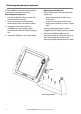
There are two mounting arrangements: Flush Mounting the 8120/8084 1. Attach the flush mounting template to the selected mounting position using adhesive tape. 2. Drill a pilot hole for each of the hole saw cuts shown on the template before cutting the larger hole with the hole saw. 3. Next cut all the way around the inside of the cut-out line with a saw to remove the waste material shown on the template. 4. Check that the unit fits correctly in the cut out area. Adjust the fit with a file if required. 5.
20-4 Installation: Power/data cable The power/data cable has a black locking collar and flying leads. 1 Wire the Instrument for auto power to have the Instrument turn on with the boat’s ignition switch or to record engine hours or if the Instrument must add up the total fuel used (for example if NAVMAN petrol/gasoline fuel sensors are installed or if SmartCraft is installed without fuel tank level sensors). Otherwise wire for basic power (for more information, see section 2-2).
20-5 Installation: GPS antenna Selecting an antenna Fit one of these GPS antennas: • Normally use the GPS antenna supplied. • An optional differential beacon DGPS antenna to give enhanced accuracy within range of land based differential beacons in areas where WAAS or EGNOS are not available. Such a DGPS antenna has both a GPS receiver and a beacon receiver, and it automatically applies the beacon correction to the GPS position.
20-6 Installation: Sonar transducer ! WARNING Do not install plastic through hull transducers in solid wooden hulls. Leakage through the hull may result. Do not install bronze transducers in metal hulls. This will cause electrolytic corrosion that may result in damage to the hull or transducer. Sonar cable Blue Connect the transducer to the blue Instrument connector; tighten the locking collar.
20-9 Installation: SmartCraft If the boat has one or two SmartCraft capable Mercury petrol/gasoline engines, connect the Instrument to the SmartCraft engines with an optional SmartCraft gateway. The display unit can display engine data and trim and can control troll speed. Note: Fit a single gateway for single engines and a dual gateway for dual engines. SmartCraft engines have fuel flow sensors, therefore NAVMAN fuel sensors are not required as well.
20-11 Installation: Other NavBus instruments NavBus is NAVMAN’s system for connecting instruments together to interchange data and share transducers. When instruments are connected by NavBus: If the units, alarms or calibration are changed in one instrument, then the values will automatically change in all other instruments of the same type. Each instrument can be assigned to a group of instruments.
20-12 Installation: Other NMEA instruments NMEA is an industry standard for interconnecting instruments. It is not as flexible or as easy to install as NavBus. The Instrument can: Receive and display wind speed and direction from an optional compatible wind instrument. Receive and display depth, paddlewheel boat speed and water temperature from an optional compatible instrument. Receive data from an optional compatible GPS or GPS/DGPS source.
Appendix A - Specifications GENERAL Sonar output: 8120 Size: 256 mm (10.08“) H x 385 mm (15.16“) W x 78.5 mm (3.09“) D. Allow 3 mm clearance on each side for dust cover. 8084 Size: 190 mm (7.48“) H x 285 mm (11.22“) W x 76.8 mm (3.02“) D. Allow 3 mm clearance on each side for dust cover. Power: Variable, up to 600/1000 W RMS Dual frequency: 50 khz and 200 kHz Depth acquisition time from startup: Typically 2 seconds at 30 m (100 ft) Temperature: 8120 Display: 307 mm (12.
Physical Dimensions NAVMAN 8120 NAVMAN 8084 NAVMAN 8120/8084 Installation and Operation Manual 103
List of datums Adindan American Samoa 1962 ARC 1950 Astro Beacon ‘E’ 1945 Astro Tern Island (Frig) 1961 Ayabelle Lighthouse Bissau Camp Area Astro Cape Chatham Island Astro 1971 Corrego Alegre Djakarta (Batavia) European 1950 Gan 1970 Guam 1963 Herat North Hong Kong 1963 Indian 1954 Indonesian 1974 ISTS 073 Astro 1969 Kerguelen Island 1949 L. C. 5 Astro 1961 Luzon Massawa Minna Nahrwan United Arab Emirates North American 1927 Observatorio Meteorolog.
Appendix B - Troubleshooting This troubleshooting guide is written with the assumption that the user has read and understood the relevant sections in this manual. It is possible in many cases to solve difficulties without having to send the display unit back to the manufacturer for repair. Please follow this troubleshooting section before contacting the nearest NAVMAN dealer. There are no user serviceable parts.
B-2 GPS navigation problems 2-1 No GPS fix or long time to get fix at startup: a May occur occasionally if the antenna does not have a clear view of the sky. The satellite positions are constantly changing. b Antenna cable not connected to display unit. 2-2 Instrument GPS position different from true position by more than 10 m (33 ft): a Instrument in simulate mode. Turn simulate mode off (see section 19-16). b The normal error in GPS position will exceed 10 m (33 ft) for about 5% of the time.
3-2 Flow indicates no fuel or low fuel: a Check that the number of engines is set to 1 (see section 19-6). b Check that the fuel cable connectors are securely plugged in and the collar is locked in place. The collar must be locked in place to give a watertight connection. c A fuel transducer may be clogged. If so, remove the transducer from the fuel line and gently blow through it in the opposite direction to the fuel flow.
h Ensure there is not another fishfinder or depth sounder turned on, which may interfere with this Instrument. i Electrical noise from the boat’s engine or an accessory may be interfering with the transducer(s) and/or the Instrument. This may cause the Instrument to automatically decrease the Gain unless using Manual Gain. The Instrument thus eliminates weaker signals such as fish or even the bottom from the display. This may be checked by switching off other instruments, accessories (e.g.
B-5 Radar problems 5-1 Radar overlay doesn’t appear on the chart screen a Ensure that your boat is shown on the radar window. If it is, but the radar overlay still isn’t shown, try zooming in on the charted area. (The charted area may be outside the maximum range of the radar). b The threshold or transparency settings for the radar overlay are not correct (see 18-6). 5-2 Radar shows arcs and/or shadows Side lobe patterns often appear as an arc or a broken arc. Shadows are blind spots.
Appendix C Glossary and navigation data Air temp - Air temperature (requires NAVMAN 7200 VHF radio). Alarm status - Shows the symbol (see section 19-10) for each alarm that is on. The symbol is normally black and turns red if the alarm triggers. Attention Area - An important area on a chart, such as a restricted anchorage or a shallow area (see section 19-2). AIS - Automatic Identification System. A System where vessel information (location, course, speed, etc.
SmartCraft - A feature of Mercury Marine engines for monitoring engine performance. TCPA - Time to Closest Point of Approach. Time until the closest point of approach for two vessels. Sea clutter - Rough seas can cause interference with the radar image. Sonar status - A summary of sonar settings. TTN - Time to the next position the 8120/8084 is navigating to, either a waypoint or the cursor. User card - A plug-in card that stores waypoints, routes and tracks (see section 1-2).
Navigation data BRG Bearing to Destination: Bearing to the destination from the boat. BRG Bearing to cursor: Bearing to cursor from boat (cursor mode, see section 3-2-1) CDI Course Deviation Indicator: When the boat is navigating to a point, the chart and highway windows show a parallel line on either side of the plotted course. These two lines are called the Course Deviation Indicator (CDI) lines. The distance from the plotted course to a CDI line is the CDI scale.
Appendix D Compliance statements FCC Statement Note: This equipment has been tested and found to comply with the limits for a Class B digital device, pursuant to Part 15 of the FCC Rules. These limits are designed to provide reasonable protection against harmful interference in a normal installation. This equipment generates, uses and can radiate radio frequency energy and, if not installed and used in accordance with the instructions, may cause harmful interference to radio communications.
How to contact us NORTH AMERICA BNT - Marine Electronics 30 Sudbury Rd, Acton, MA 01720. Toll Free: +1 866 628 6261 Fax: +1 978 897 8264 e-mail: sales@navmanusa.com web: www.navman.com OCEANIA Australia NAVMAN Australia Pty. Limited Suite 2, 408 Victoria Road Gladesville, NSW 2111, Australia. Ph: +61 2 9879 9000 Fax: +61 2 9879 9001 e-mail: sales@navman.com.au web: www.navman.com New Zealand Absolute Marine Ltd. Unit B, 138 Harris Road, East Tamaki, Auckland.
Lon 174° 44.535’E Lat 36° 48.