Navman 8120/8084 Fuel, AIS, & Radar Addendum 06/07 w w w . n a v m a n .
Warning AIS: The AIS features on this chart-plotter are designed as a safety aid only and do not guarantee safety at sea. AIS transmission is mandatory on some, but not all, vessels. AIS should be used to complement radar, but AIS is not a substitute for radar. Notes • AIS and Radar functions require optional accessories to be installed. • Radar is available in 2 kW, 4 kW, 6 kW units.
Fuel functions and display What the fuel computer does ! CAUTION ! WARNING To ensure the fuel data is accurate: DANGER When you add or remove fuel from a tank, tell the 8120/8084. If the boat has petrol/gasoline sensors, calibrate them during installation or if the fuel CAUTION readings seem inaccurate. Choose an appropriate type of boat speed sensor or GPS source to calculate economy, range and the fuel consumption curve.
Water speed and ground speed A paddlewheel sensor and a pitot sensor measure water speed, the boat speed through the water. A GPS measures ground speed, the boat speed over the bottom of the water. If there is a current, then these speeds will be different, and the log, trip log, economy and range will be different, as shown below. Water speed is better for measuring the boat’s potential performance, Ground speed is better for going to a destination because it takes currents into account.
Calibration Calibrate petrol/gasoline fuel flow sensors during installation, or if the fuel readings seem inaccurate and the other troubleshooting suggestions do not help. Note SmartCraft fuel sensors and NAVMAN diesel sensors are factory calibrated and should never need recalibrating. On a multi engine boat, calibrate each engine’s sensor. This can be done at the same time with a portable tank for each engine or at different times using one portable tank.
AIS AIS is short for Automatic Identification System. The International Convention for Safety of Life At Sea (SOLAS) requires all vessels greater than 300 tons and all passenger vessels to be equipped with AIS Transponders. All vessels equipped with AIS permanently broadcast via one or more of the two dedicated VHF channels. This transmission may include information about the vessels MMSI-number, its call sign, name, position, course, heading, speed, rate of turn and type of vessel.
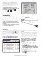
When the cursor is placed over an AIS vessel for at least two seconds, a data box appears at the bottom of the window with information about the AIS vessel. For complete AIS information of the AIS vessel place the cursor over an AIS vessel for at least two seconds and press . Press either or to clear the information. Dangerous Vessels The 8120/8084 calculates the time of closest point of approach (TCPA) and closest point of approach (CPA) for each AIS vessel.
Displaying Full AIS Details Filter by Type 1 Press or to select a vessel. 2 Press and select More Info or press . This window displays all information for the selected AIS vessel provided by the AIS receiver. Sorting Vessels Press , select Sort and select one of the options. This sorts the list based on the chosen category. Safety msgs (rx) Safety msgs (rx) are broadcasted messages received by the AIS receiver.
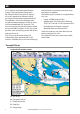
Radar The scanner rotates through 360° so the radar window shows all of the area around your boat within the range of the scanner, producing a map-like display called the PPI (Plan Position Indicator). Typically, your boat is in the centre of the radar window with concentric range rings surrounding it. The range rings help you to quickly estimate the distance to various targets. You can also view the radar overlaid on the chart screen. Radar is the Radio Detection And Ranging system.
Radar modes There are four radar modes: • Disabled. This saves on power consumption and magnetron usage. If the radar is disabled, it has to warm up and enter standby mode before it can start transmitting. • Warming. The radar on and is warming up. This can take up to 90 seconds, depending on your scanner type. • Standby. The radar is on and is warmed up. It is ready to start transmitting immediately. • Transmitting. The radar is actively sending and receiving microwave radio pulses.
separation or take into account viewing conditions. 1 Press MENU twice. 2 Select Radar. 3 Select Overlay palette. 4 Select your color preference. Overlay Transparency The transparency of the radar overlay can be adjusted, in case it obscures important chart features. 1 From the chart screen or pane, press MENU once. 2 Select Radar overlay. If the box is unchecked, press ENTER . A Radar menu option appears below. 3 Select Radar. 4 Select Transparency. 5 Adjust the slider to suit.
Changing the gain level Changing the sea clutter level Use the radar gain level to adjust the sensitivity of the radar receiver. Ideally, the radar gain level should be set so that background noise is just visible on the radar window. If the radar gain level is too low, weak echoes won’t be shown. If the radar gain level is too high, strong echoes will be difficult to see amongst the large amount of background noise.
Changing the echo expansion setting If you have several small targets in view and want to make them easier to see, use the echo expansion option. Note that the resolution decreases as the target size increases, so use this option only when target detection and visibility is more important that the quality of the display. To change the echo expansion setting: From the radar window, press then select Echo Expansion. There are three choices: • Off. No echo expansion. • 1. Targets expanded x 2. • 2.
Finding range and bearing with a fixed VRM/EBL 1 From the radar window, press then select VRM/EBL. 2 Select VRM/EBL then 1 (VRM/EBL 1) or 2 (VRM/EBL 2). 3 Set Enable to to show the VRM and EBL on the radar window (or to hide them). 4 Select EBL reference if you want to change the EBL bearing reference. There are two choices: • °R shows the EBL bearing relative to your boat’s head. • °M/°T shows the EBL bearing relative to magnetic North or true North.
Changing the PPI position You can move the PPI (Plan Position Indicator) centre to a different location if you are in Relative motion mode. (If you are in True motion mode, the radar automatically positions the PPI centre.) To change the PPI position: 1 From the radar window, press then select Position. 2 There are three choices: • Centre. The PPI centre is in the centre of the radar window so that all other objects move relative to your boat. • Look Ahead.
Adjusting the boundaries of a radar guard zone To adjust the boundaries and change the area that is covered by a radar guard zone: 1 From the radar window, press then select Guard Zone. 2 Select Zone then 1 (radar guard zone 1) or 2 (radar guard zone 2). 3 Select Adjust to display the current boundaries of that radar guard zone. The following information is also shown in the top left corner: • Guard Zone: The number shows the radar guard zone that is selected.
• Head up means that the radar image rotates underneath your boat, so the direction in which you are heading is pointing to the top of the radar screen. You can easily compare the visual view in front of your boat with the radar screen. • Course up works only when COG data or heading data from a heading sensor is available and there is an active route.
Heading line The heading line is a white line that extends from your boat to the edge of the radar window. Show the heading line. Hide the heading line. Setup > Radar > Installation Note: This option is shown only when the radar is enabled (see Manual, 18-3) 1 Press twice to display the Setup menu, then select Radar. 2 Select Installation: Park position If your radar has an open array and you take it out of enabled mode, the open array continues to rotate for a short distance before it finally stops.
Radar problems Radar overlay doesn’t appear on the chart screen a Ensure that your boat is shown on the radar window. If it is, but the radar overlay still isn’t shown, try zooming in on the charted area. (The charted area may be outside the maximum range of the radar). b The threshold or transparency settings for the radar overlay are not correct. Radar shows arcs and/or shadows Side lobe patterns often appear as an arc or a broken arc. Shadows are blind spots.
Physical Dimensions NAVMAN 8120 NAVMAN 8084
Lon 174° 44.535’E Lat 36° 48.