FISH 4200 F I S H F I N D E R S w w w. n a v m a n .
FCC Statement Note: This equipment has been tested and found to comply with the limits for a Class B digital device, pursuant to Part 15 of the FCC Rules. These limits are designed to provide reasonable protection against harmful interference in a normal installation. This equipment generates, uses and can radiate radio frequency energy and, if not installed and used in accordance with the instructions, may cause harmful interference to radio communications.
Contents 1 Introduction ..................................................................................................... 5 2 Getting started ................................................................................................. 6 2-1 Simulation Mode .......................................................................................................... 7 3 Operation ......................................................................................................... 7 3-1 ALARMS .....
Important It is the owner’s sole responsibility to install and use the instrument and transducers in a manner that will not cause accidents, personal injury or property damage. The user of this product is solely responsible for observing safe boating practices. NAVMAN NZ LIMITED DISCLAIMS ALL LIABILITY FOR ANY USE OF THIS PRODUCT IN A WAY THAT MAY CAUSE ACCIDENTS, DAMAGE OR THAT MAY VIOLATE THE LAW.
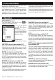
1 Introduction Congratulations on choosing a NAVMAN fishfinder. For maximum benefit, please read this manual carefully before installation and use. This manual describes the installation and operation procedures for the FISH 4200. The NAVMAN Fishfinder The FISH 4200 is an ultrasonic fishfinder with four levels of greyscale. It provides powerful software and a large, high-resolution screen with a zoom facility and a choice of fish symbols.
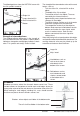
2 Getting started Power and transducer connection The FISH 4200 has two sockets located on the rear of the unit. The power cable has a black 8 pin LT connector plug. Push this plug into the lower socket, which has a black nut and is located on the rear of the display unit, then turn the collar to lock. Make sure that the collar is secure for a watertight connection. The transducer cable has a blue 8 pin LT connector plug.
2-1 Simulation Mode An internal simulator allows users to learn how to operate the fishfinder off the water. In Simulation mode the word “SIMULATION” flashes on the bottom of the screen. The fishfinder generates data so that all the main screens appear to be operational. Any changes made to the contrast, backlighting, alarms or the display setup are saved. To turn the Simulation mode on, power the FISH 4200 off, disconnect the blue transducer plug at the rear of unit, then turn the power on.
3-1 ALARMS Alarms can be enabled to automatically detect certain conditions, such as the water being too shallow. The trigger settings for the alarms can be defined to suit the boat and individual preferences. The FISH 4200 has seven alarms, TOO SHALLOW, TOO DEEP, FISH ALARM, TEMP VALUE, TEMP RATE, LOW BATTERY and LOW FUEL. The alarm symbols and beeper cycles for all of the alarms are shown in section 4-1.
Changing the Gain Mode Fish detection and display Gain (sensitivity) controls the amount of detail displayed on the screen. The FISH 4200 has two gain modes, Auto Gain and Manual Gain: The fish symbol option can be customized, or switched off altogether so that the echoes are not converted to fish symbols on the screen. Section 4-4 explains how to do this. The differences between Fish symbols on and off are: · In Auto Gain, the gain is automatically adjusted to compensate for water depth and clarity.
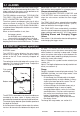
The following picture shows the HISTORY screen with the fish symbols turned off: The strength of the returned echo varies with several factors, such as: · Single fish Large school of fish Small school of fish Bottom Strength of returned echoes The shading indicates differences in the strength of the returned echo from the bottom. A black pattern indicates a strong echo, and light grey indicates a weak echo. Fish symbols are always shown in black. The size of the fish, school of fish or other object.
NAVMAN fishfinders display the most recent events on the right of the screen. Moving boat 1 minute ago 30 seconds ago Now Air in water (e.g. from wake) When the fish symbol option is ON, any echo returned that fits the profile of a fish is displayed on the screen with a fish symbol. Stationary boat 1 minute ago Now Time When a boat is stationary, all bottom echoes will come from the same small area of bottom. This will produce a flat bottom trace on the screen.
3-4 ZOOM screen Select MAIN MENU - ZOOM to display the ZOOM screen. as fish or features close to the bottom) in greater detail than the HISTORY screen. The ZOOM screen is split into two parts. On the right is the full range section (just like the HISTORY screen) and on the left is the zoom section. Bottom Lock Full range section The zoom bar is normally locked to the bottom (Bottom Lock) so that the bottom is always displayed in the zoom section, regardless of changes in depth.
return on the fishfinder is seen, it is likely to be the same fish species. Gain setting Adjusting the Shading Bar These echoes will be shown in grey on the Fish History section. The Shading Bar is displayed as a horizontal bar in the lower half of the screen. Adjust the Shading Bar so different strength echoes have a different shade on the screen. Weaker echoes can be shown as light grey, and the strongest echoes shown as black. These strong echoes will be shown in black on the Fish History section.
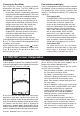
3-7 DATA screen Select MAIN MENU - DATA to display the DATA screen: Temperature Temperature Graph Battery voltage Log Engine hours Speed Enabled alarms Depth A graph displays the surface water temperature for the last 40 minutes and is updated every 30 seconds. The current water temperature is displayed above the graph and is updated every second. The temperature can be displayed in °F (Fahrenheit) or °C (Celsius).
3-9 RANGE menu Select MAIN MENU - RANGE to change the manual range and adjust the selected depth range. The range setup box is displayed. This shows the depth of water displayed vertically and the range mode setting. NAVMAN’s FISH 4200 has two range modes, Auto Range and Manual Range. The use of Auto Range is recommended. See section 3-2 for more details. To change between Auto Range and Manual Range, press . The Manual Range mode offers the user a choice of pre-selected water depths.
4 SETUP menu Select MAIN MENU - SETUP to display the SETUP menu: Use the SETUP menu to customize the FISH 4200 to suit the boat and individual preferences, as follows: · specify the trigger settings for the alarms (see section 4-1) · choose the units for depth, temperature, speed and fuel (see section 4-2) · turn the key beep on or off (see section 4-3) · choose the fish symbol (see section 4-4) · choose the contrast level (see section 4-5) · select the Trip Log or the Total Log (see section 4-6) · zero T
Alarms automatically re-enable The TOO SHALLOW, TOO DEEP and LOW BATTERY alarms automatically re-enable when the value moves outside the alarm trigger setting. The TEMP VALUE alarm automatically re-enables when the temperature is more than 0.45°F (0.25°C) above or below the alarm trigger setting. The TEMP RATE alarm automatically re-enables when the rate of temperature change falls below the trigger setting by more than 0.2°F (0.1°C) per minute.
4-2 UNITS menu Select MAIN MENU - SETUP - UNITS to define the units for depth, temperature, speed and fuel. Press or an option. to highlight DEPTH Can be displayed in units of feet (FT), fathoms (FA), or metres (M). Press to select the required depth units. TEMPERATURE SPEED Can be displayed in knots (KN), miles per hour (MPH), or kilometres per hour (KPH). Press to select the required speed units. Note: Distance units will change automatically to match the speed units.
4-6 LOG menu Select MAIN MENU - SETUP - LOG to display the available options. Press or an option: to highlight LOG Selects which log is displayed on the DATA screen, TOTAL or TRIP. ZERO TRIP LOG Resetting the trip log will return the trip log value to zero. The trip log is retained in the fishfinder memory so it retains the distance value if the fishfinder is switched off during a trip. Therefore, the trip log needs to be reset manually each time the user wishes to log a trip.
4-8 INSTALL menu Use this menu at installation time, to select the language and to enter the keel offset value, the number of engines and the fuel tank size. The INSTALL menu can also be used to calibrate the water temperature and boat speed. Select MAIN MENU - SETUP - INSTALL to display the menu. Press or an option. to highlight LANGUAGE The following languages are available: English, French, German, Spanish, Italian, Dutch, Swedish, Portuguese and Finnish.
4-9 CALIBRATION menu Calibrating the Fuel Use this menu to calibrate water temperature boat speed, fuel readings and the fuel flow filter. Use this to calibrate the fuel usage. Calibrating the fuel usage can improve the accuracy of fuel measurements. Twin engine installations require each fuel transducer to be calibrated. This can be done at the same time with two portable tanks, or at different times using one portable tank.
Setting the Flow Filter Period Normally engines do not draw fuel from the tank at a steady rate. To give a stable fuel flow reading, the TRACKER calculates the flow values by taking several measurements and averaging them. The flow filter sets the period over which the fuel flow is averaged, and can be set from 1 to 255 seconds or Off. Set the flow filter to the lowest value which give a stable flow. Usually a value of 10 to 15 seconds will give a satisfactory result for two-stroke carburettor engines.
5 Installation Correct installation is critical to the performance of the FISH 4200. There are two components to install, the display unit and the transducer. It is vital to read the entire installation section of this manual and the documentation that comes with the transducer before attempting installation.
5-4 Wiring Connection Auto Power Wiring Warning 1 Amp fuses must be positioned where shown in the wiring diagrams. If possible, route the transducer cables away from other wiring on the boat. Electrical noise from engine wiring, bilge pumps and other electrical equipment can affect the unit. The shortest and most direct connection to the boat's battery helps to minimise voltage drop. Ensure that any cable connections do not lay in the bilge.
Single Engine Fuel Wiring Option Twin Engine Fuel Wiring Option Black Red 8 pin Black Black fuse Power fuel cable 2m 8 pin Black 8 pin White 8 pin White Red fuse Power fuel cable 2m 8 pin White cable 8m cable 8m cable 8m Twin engine fuel adaptor Fuel Transducer Fuel Transducer Port Fuel Transducer Starboard 5-5 Connecting a FISH 4200 to other instruments Several NAVMAN instruments can be connected together to share data such as Depth or Speed.
Appendix A - Specifications Depth range · 2 ft (0.6 m) to 600 ft (180 m) Display type · FSTN greyscale · Screen resolution 160 high x 120 wide (pixels) · Amber multi-level back lighting Supply voltage · 10 to 16.
Appendix B - Troubleshooting This troubleshooting guide is written with the assumption that the user has read and understood the relevant sections in this manual. It is possible in many cases to solve difficulties without having to send the display unit back to the manufacturer for repair. Please follow this troubleshooting section before contacting the nearest NAVMAN dealer. There are no user serviceable parts.
is located. To stop problems from electrical noise, try: - rerouting the power and transducer cable(s) away from the boat’s other electrical wiring. - routing the unit's power cable directly to the battery instead of through a fuse block or ignition switch. 4. Bottom is not displayed: a) The fishfinder may have Manual Range selected and the depth may be outside the range value selected. Either change the fishfinder to Auto Range or select another depth range - see section 3-9.
11. A twin engine installation shows only one flow rate: a) Check that the number of engines is set to 2. See section 4-8. 12. Erratic fuel FLOW readings: a) The fuel flow transducer may have been mounted too close to the fuel pump, or may be subject to excessive vibration. Refer to the Installation Instructions supplied with the fuel transducer. b) Check for air leaks in the fuel line or in the fuel pickup in the tank. c) The FLOW FILTER value is not suitable for the engine.
NAVMAN FISH 4200 Installation and Operation Manual
NAVMAN FISH 4200 Installation and Operation Manual 31.
Lon 174° 44.535'E FISH 4200 Made in New Zealand MN000160 1951407A NAVMAN Lat 36° 48.