FU EL 2100 Installation and Operation Manual w w w. n a v m a n . c o m English ............. 3 Français ......... 11 Español .......... 19 Deutsch .......... 27 Nederlands .... 35 Svenska ......... 43 Suomi .............
FCC Statement Note: This equipment has been tested and found to comply with the limits for a Class B digital device, pursuant to Part 15 of the FCC Rules. These limits are designed to provide reasonable protection against harmful interference in a normal installation. This equipment generates, uses and can radiate radio frequency energy and, if not installed and used in accordance with the instructions, may cause harmful interference to radio communications.
Contents 1 Operation ......................................................................................................... 4 Fuel Flow ........................................................................................................................... 4 Other Fuel Functions ......................................................................................................... 4 Changing the fuel remaining value ....................................................................................
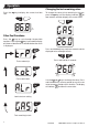
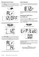
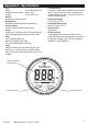
1 Operation Fuel Flow Press the rate. Changing the fuel remaining value key to display the current fuel flow ^ FLOW two seconds and then displays the current value. V TOTAL To change the value of fuel remaining in the tank, press the key until the display indicates for ^ FLOW V TOTAL " # Other Fuel Functions Press the key to cycle through the possible functions. Each time the key is pressed the display will show an identifier for 2 seconds before the value is displayed.
Setting the low fuel alarm Alarm activation Use the key to select the alarm function. The LCD will indicate ALr for two seconds and will then display the present alarm value. If no alarm value has been entered the LCD will indicate 0FF . If the fuel remaining value drops below the fuel alarm value, the alarm will sound and the alarm arrow will flash. ^ FLOW V TOTAL ALr 012 0FF Press and hold both keys for three seconds and the displayed value will begin to flash.
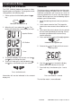
2 Instrument Setup Selecting units of measure Calibration The FUEL 2100 will indicate fuel values in Litres, Imperial gallons or US gallons. To change the current setting perform the following steps: The fuel transducer supplied with the fuel flow meter will provide readings at better than 5% accuracy. Individual calibration will increase this level of accuracy to better than 2% over a fuel flow range of 10.0 to 120 litres per hour. Use the following steps to calibrate your fuel flow meter: 1.
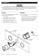
3 Installation WARNING IT IS VERY IMPORTANT TO INSTALL A FUEL FILTER BETWEEN THE FUEL FLOW TRANSDUCER AND THE FUEL TANK. THIS FILTER WILL CATCH LARGER PARTICLES OF DIRT FROM THE FUEL TANK AND PREVENT THE FINE GAUZE FILTER IN THE FUEL FLOW TRANSDUCER FROM BECOMING BLOCKED AS THIS MAY DAMAGE THE ENGINE. Location Mounting The FUEL 2100 is designed for above or below deck installation. Select a position that is: The instrument panel must be 3mm to 19mm (1/8" to 3/4") in thickness.
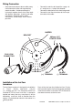
Wiring Connection • Keep electrical and transducer cables away from alternator or other noise generating electrical cables. Avoid connecting the instrument to power circuits that share loads with ignition, alternators, inverters and radio transmitters. Electrical power supply connections should always be as short as possible. • Connect the red wire to the positive supply via a 1 amp fuse or a 1 amp circuit breaker. Connect the black wire to the electrical ground.
Appendix A - Specifications • Size Mount 51mm diameter hole Depth behind face plate 95mm max. Display 3-character LCD • Colour Black with texture on bezel. • Backlighting Red coloured diffused lighting for display. • Water Integrity Front will withstand direct water spray. • Alarm Audio and visual alarm indicates remaining fuel total has dropped below a preset alarm value. • Flow 2.5 to 160 litres per hour 0.5 to 43 US gallons per hour 0.
Appendix B - Troubleshooting Chart No display: 1. Check DC power connections and DC polarity with voltmeter. 2. Check fuse. No flow reading indicated: 1. Check connection to flow transducer. 2. Remove transducer from fuel line, blow through transducer, a whistling noise will indicate the turbine is rotating. Low flow reading indicated: 1. Check that the gauze filter is clean. If the filter is not installed fine strands may clog up the turbine. 2. Check calibration is correct.
Appendix C - How to contact us www.navman.com . NORTH AMERICA ASIA e-mail: thonge@cscoms.com Website: www.plastimo.it NAVMAN USA INC. 18 Pine St. Ext. Nashua, NH 03060. Ph: +1 603 577 9600 e-mail: sales@navmanusa.com China Peaceful Marine Electronics Co. Ltd. Hong Kong, Guangzhou, Shanghai, Qindao, Dalian. E210, Huang Hua Gang Ke Mao Street, 81 Xian Lie Zhong Road, 510070 Guangzhou, China. Ph: +86 20 3869 8784 e-mail: sales@peaceful-marine.com Website: www.peaceful-marine.com Vietnam Haidang Co.
Lon 174° 44.535’E FUEL 2100 Made in New Zealand MN000207A NAVMAN Lat 36° 48.