www.navman.
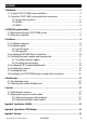
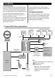
Contents 1 Introduction ..........................................................................................................................................5 1-1 A typical G-PILOT 3380 system installation . . . . . . . . . . . . . . . . . . . . . . . . . . . . . . . . . . . . . . . . 5 1-2 Using the G-PILOT 3380 system with other instruments . . . . . . . . . . . . . . . . . . . . . . . . . . . 6 1-2-1 Using other instruments . . . . . . . . . . . . . . . . . . . . . . . . . . . . . . . . . . . . . .
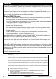
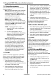
Important It is the owner’s sole responsibility to install and use the instrument and transducer/s in a manner that will not cause accidents, personal injury or property damage. The user of this product is solely responsible for observing safe boating practices. The choice, location, and installation of all components in any autoG-PILOT system is critical. If installation is not correct, the unit can not perform at its designed potential. If in doubt, consult your Navman dealer.
1 Introduction Using this manual This manual describes how to install and set up the G-PILOT 3380 system. Refer to the separate G-PILOT 3380 Operation Manual for information on how to operate the G-PILOT 3380 display unit. To install a G-PILOT 3380 system, you must perform installation, dockside setup and sea trials (see sections 3, 4 and 5). To fully set up a G-PILOT 3380 system after a part has been changed or if a problem is suspected, perform dockside setup and sea trials again (see sections 4 and 5).
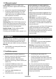
1-2 Using the G-PILOT 3380 system with other instruments 1-2-1 Using other instruments Comms menu, in the G-PILOT 3380 Operation Manual). If you change the backlight in an instrument in group 1, 2, 3 or 4 then the backlight will automatically change in the other instruments in the same group. If you change the backlight in an instrument in group 0 then no other instruments are affected.
G-PILOT 3380 system NMEA outputs WIND: The G-PILOT 3380 system can receive NMEA wind data from a compatible wind instrument: True or apparent wind direction (from MWV sentences) is required for the G-PILOT 3380 system to use Wind mode.
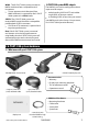
2-2 Other parts required Power supply: The G-PILOT 3380 system requires two power supplies, both nominally 12 V DC: A heavy duty supply for the steering drive A light duty supply for the G-PILOT 3380 system electronics and display unit; this supply also powers any additional display units and other instruments. The power supplies require one or two switches and fuses or circuit breakers (see section 3-4).
3-2 Installation guide This is a general guide for locating and wiring the parts of the G-PILOT 3380 system. The instructions for a particular part may have additional requirements. 3-2-1 Location guide 3-2-2 Wiring guide Do not mount any part where it can be used as a handhold, where it will interfere with the operation of the boat or where it might be submerged.
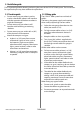
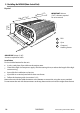
3-3 Installing the MCU600 (Main Control Unit) Physical 55 mm (2.16”) 200 mm 1 200 mm (7.87”) IMPORTANT: 200 mm (7.87”) clearance required for cover removal (7.87”) 2 3 Sc re ws 14 0 m 90 m m m (5. (3.54 10 ”) ap ”) ar 60 s1 ole t ( mm 6 2.3 84 mm h ew Scr ”) 24 (7. rt pa ”) a 1 RFU 2 Gyro 3 Compass / Heading Sensor IMPORTANT: 60 mm (2.36”) clearance required for cables Installation Find a suitable location for the unit: In a dry, cool place; if possible not the engine room.
3-4 Installing the power supplies and steering drive 3-4-1 Installing the power supplies MCU600 The MCU 600 system requires a light duty and a heavy duty power supply, both 12 V DC. Note: Keep all wiring as short as possible. For the heavy duty supply, use the wire size given in the table (see section 3-4-2). Follow the wiring guide (see section 3-2-2). Power supply: one switch configuration Choose this configuration to have one switch to turn the G-PILOT 3380 system and any other instruments on and off.
3-4-2 Installing the steering drive Install the steering drive according to one of the diagrams on the following pages. Note Keep all wiring as short as possible. Use the wire size given in the table below. Follow the wiring guide (see section 3-2-2). Wire less than #10 gauge will not fit directly into the four way terminal block. Fit ferrules or reterminate the wire with #10 gauge wire.
Example of hydraulic steering with hydraulic help pump. In the Setup > Vessel menu (See G-PILOT 3380 Operation Manual), set Drive Type to Motor. MCU600 Fit strain relief No connection Heavy duty power (see section 3-4-1) Wiring polarity does not matter. Motor Example of mechanical steered power vessels with hydraulic linear drive for sailing boat In the Setup > Vessel menu (See G-PILOT 3380 Operation Manual), set Drive Type to Motor.
Installing a electric drive motor with clutch relay In the Setup > Vessel menu (See G-PILOT 3380 system Operation Manual), set Drive Type to Motor. MCU600 Fit strain relief Connector cover Heavy duty power (see section 3-4-1) 1N4002 diode or equivalent Fit close to relay coil Relay contacts Clutch coil Wiring polarity does not matter. Motor Relay coil 1N4002 diode or equivalent. Fit close to relay coil Note: Relay is required if the clutch circuit is greater than 300 mA.
Installing solenoid valves or relays with jog or electric steering In the Setup > Vessel menu (See G-PILOT 3380 Operation Manual), set Drive Type to Spool ground.
3-5 Installing the RFU (rudder feedback unit) Physical Rudder shaft Base 90 mm (3.5”) LT8 connector 10 m (33 ft) cable 220 mm (8.7”) Arm Linkage to rudder Connecting rod, with quick release fittings and lock nuts each end Mounting requirements These two distances to be equal. Arm rotates freely around base. End of connecting rod snaps into one of the holes on the arm. These two distances to be equal. Adjust position of rod on arm if required. Rudder shaft to be parallel to shaft in base.
Alignment The arm can rotate freely around the base. When the rudder is amidships, the arrow on the arm must point to one of the centre lines on the base. Centre line Base Sets of lines show the two linear ranges of the unit. Centre line Therefore in an installation, the base can be rotated to two positions. We recommend the position that has the cable on the opposite side to the connecting rod. Recommended (rudder amidships). Not recommended, cable can foul rudder linkage.
Installation 1 2 3 Find a suitable location and arrangement for the unit as described above. Choose, assemble and fit a suitable rudder linkage. Fit the unit as shown below: Set rudder amidships. If necessary, mount base on block to set height. Rotate base so arrow on arm points near centre line on base. Fit two screws provided loosely in middle of slots. Rotate base so arrow on arm points to centre line on base. Fit third screw provided, tighten all screws. Ensure rudder is amidships.
3-6 Installing the Compass Physical 71 mm, (2.8”) 101 mm, (4”) 97 mm, (3.8”) Mounting holes for screws LT8 connector 10 m (32.
Installation 1 2 Find a suitable location for the unit as described above. Mount the unit with the three screws provided. Use a level to ensure the unit is vertical to within 10°. Less than 10° 10° Less than 10° 10° 3 Wire the cable back to the MCU600, following the wiring guide (see section 3-2-2). MCU600 Holes in the bulkheads must be at least 18.5 mm (0.73 in) diameter.
3-7 Installing the Gyro Physical 101 mm, (4”) 71 mm, (2.8”) 97 mm, (3.8”) Mounting holes for screws LT8 connector 10 m (32.8 ft) Location Mount the gyro as close as possible to the centre of movement of the boat, to minimize how much the gyro moves when the boat rocks and pitches. Mount the gyro on a panel which does not vibrate. The unit is completely waterproof but should not be immersed. Follow the location guide (see section 3-2-1).
Installation 1 2 3 Find a suitable location for the unit as described above. Mount the unit with the three screws provided. Use a level to ensure the unit is vertical to within 10°. Less than Less than 10° 10° 10° 10° Wire the cable back to the MCU600, following the wiring guide (see section 3-2-2). Holes in the bulkheads must be at least 18.5 mm (0.73”) diameter.
Bracket mounting requires a panel for mounting the bracket. Ensure that the panel is not likely to deform and is not subject to excessive vibration. The bracket can be tilted and the dispaly can be removed after each use. Select a position where the display unit will be: • At least 4" (100 mm) away from the compass. • At least 12" (300 mm) away from any radio transmitter. • At least 4 ft (1.2 m) away from any antenna. • Easy to read and operate.
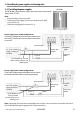
Wiring the display unit Display unit Plug power cable into the Black socket on the rear of the G-PILOT 3380 display. MCU600 Clutch relay out: NMEA2 - in/out: NMEA1 - in: NMEA common: NavBus -, Blue: NavBus +, Orange: Ground, Black: 12 V power +, Red: 8 7 6 5 4 3 2 1 Connector cover Display unit cable, Requires 18 mm (0.7”) hole through bulkhead.
Wiring other instruments Addtional G-PILOT Other series A GPS, such as a 3380 or G-PILOT 3100 instruments Navman display units TRACKER 5600 Display units GPS Units MCU600 NMEA in & out 8 7 6 5 4 3 2 1 Clutch, optional (see section 3-4-2) NMEA in/out Connector cover Clutch relay out: NMEA2 - in/out: NMEA1 - in: NMEA common: NavBus -, Blue: NavBus +, Orange: Ground, Black: 12 V power +, Red: Power, NMEA in GPS NMEA out GPS NMEA common Light duty power (see section 3-4-1) Green (from one display uni
4 Dockside setup Perform the dockside setup: after installing a G-PILOT 3380 system (see section 3) after a part has been changed or if a problem is suspected After dockside setup, perform the sea trials (see section 5 ). 4-1 Start dockside setup 1 2 3 Turn the G-PILOT 3380 system on (See G-PILOT 3380 Operation Manual). If the rudder moves, immediately turn the power off.
5 Sea trials Perform the sea trials: After performing the dockside setup (see section 4). To check the operation of the G-PILOT 3380 system. For the sea trials, sail in an open area where there are no other craft or obstructions. The sea should be calm, the wind speed as low as possible and there should be no currents. 5-1 Calibrating the compass Note To exit the calibration at any time, press ESC.
Appendix A - Specifications - MCU600 Electrical: Drive power supply: 10.5 to 16.5 V DC, 20 A maximum MCU600 Main unit Drive connections: 8-Way Terminal power supply: 10.5 to 16.5 V DC, 300 mA. Terminal Other optional instruments: refer to the instrument’s operation manual. Interfaces: NavBus: connection to other Navman instruments and G-PILOT 3380 display unit.
Appendix B - Specifications - AP3380 Display Electrical: Standards compliance: Supply voltage: 10.5 to 30.5 V DC. Supply current ( at 13.8 V): Without backlighting: 160 mA. With full backlighting: up to 410 mA. EMC compliance: USA (FCC): Part 15 Class B Europe (CE): IEC 60945:2002 Clause 9 & 10. New Zealand and Australia (C Tick): IEC 60945:2002 Clause 9. Other optional instruments: refer to the instrument’s operation manual.
Appendix C - User data User Data table (to record installation setup data) Menu > Setup > SYSTEM menu Language Night mode Key beep Auto power off SmartCraft Menu > Setup > OPTIONS menu Dodge angle Tack mode Tack angle Gybe mode Gybe angle Tack delay Turn rate Menu > Setup > VESSEL menu Vessel Type Drive Type Wind features selected Menu > Setup > ALARMS menu Course error XTE Waypoint akn Wind shift (sail only) Low battery High current 30 NAVMAN G-PILOT 3380 System Installation Manual
Menu > Setup > UNITS menu Distance Compass Magnetic variation Wind Menu > Setup > COMMS menu NMEA mode NavBus group Menu > Setup > PROFILES menu Profile (user1) Parameters: Adaptive Response Ratio Advanced: Trim C-rudder GPS gain Wind gain Profile (user2) Parameters: Adaptive Response Ratio Advanced: Trim C-rudder GPS gain Wind gain G-PILOT 3380 System Installation Manual NAVMAN 31
Profile (user3) Parameters: Adaptive Response Ratio Advanced: Trim C-rudder GPS gain Wind gain Profile (user 4) Parameters: Adaptive Response Ratio Advanced: Trim C-rudder GPS gain Wind gain Profile (user5) Parameters: Adaptive Response Ratio Advanced: Trim C-rudder GPS gain Wind gain
Lon 174° 44.535’E Lat 36° 48.