
Installation Instructions

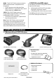

10 NAVMAN G-PILOT 3380 System Installation Manual
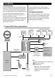
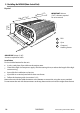
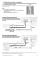
3-3 Installing the MCU600 (Main Control Unit)
Physical
IMPORTANT: 200 mm
(7.87”) clearance required
for cover removal
Installation
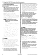
Find a suitable location for the unit:
In a dry, cool place; if possible not the engine room.
Close to the high-current power supply and the steering drive, to reduce the length of the high
current wiring.
Accessible for installation and service.
If possible on a vertical panel which does not vibrate.
Follow the location guide (see section 3-2-1).
Mount the unit with the cable connectors at the bottom or to one side, using the screws provided.
Do not mount the unit with the connectors at the top, because dust or moisture might enter the unit.
200 mm (7.87”)
IMPORTANT: 60 mm (2.36”)
clearance required for cables
200 mm (7.87”)
140 mm (5.10”)
60 mm (2.36”)
Screws 90 mm (3.54”) apart
Screw
holes 184 mm (7.24”) apart
55 mm
(2.16”)
1
2
3
1
RFU
2
Gyro
3
Compass /
Heading Sensor