Jupiter 32 Miniature 20-channel GPS receiver module Integrator’s Manual Related documents • Jupiter 32 Product Brief LA000268 • Jupiter 32 Data Sheet LA000267 • Jupiter Development Kit Guide LA000645 • Low Power Operating Modes Application Note LA000513 • Jupiter 32/30 Saving and retrieving configuration data to Flash and Selectable user profiles Application Note LA000266 • Navman NMEA Reference Manual MN000315 • SiRF Binary Protocol Reference Manual, MN000314 LA000605D © 2007 Navman New Zealand.
Contents 1.0 Introduction........................................................................................................ 1 2.0 Hardware application information................................................................... 1 2.1 Electrical connections (SMT pad interface)................................................................... 2 2.2 Typical application circuit.............................................................................................. 3 2.2.
Figures Figure 2-1: Jupiter 32 mechanical layout............................................................................. 3 Figure 2-2: Basic Jupiter 32 application circuit.................................................................... 4 Figure 2-3: Example PCB layout for external active antenna.............................................. 4 Figure 2-4: Decoupling Capacitor Placement.....................................................................
1.0 Introduction The Navman Jupiter 32 module is a complete GPS receiver designed for surface mount assembly integration. The Jupiter 32 provides a simple, cost effective GPS solution for application designers. Application integration will vary primarily with respect to antenna system design and EMI protective circuitry. The Jupiter 32 is the successor to the established Jupiter 30, being electrically compatible and having a very small form factor.
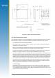
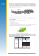
2.1 Electrical connections (SMT pad interface) The round hole on the front label side of the chip locates pad A1. The pads are designated A-F and 1-7. Details of the pad layout and numbering are shown in Figure 2-1.
All dimensions in mm Figure 2-1: Jupiter 32 mechanical layout 2.2 Typical application circuit The schematic in Figure 2-2 (next page) represents a very basic application circuit, with simple interfaces to the module. It is subject to variations depending on application requirements. 2.2.1 Power for receiver and active antenna The receiver power connection requires a clean 3.3 VDC. Noise on this line may affect the performance of the GPS receiver.
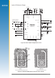
Jupiter 32 Reference Design 3.0-3.6 V 10 nF Battery 1 nF F2 VBATT F3 VCC_RF 1 uF 1 uF 1 nF 10 nF F1 PWRIN A4 VANT Coaxial Connector 50 ohm Microstrip N_GPS_FIX D4 See Section 2.
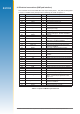
2.2.3 Decoupling The schematic in Figure 2-2 illustrates a suggested method of decoupling that may be followed. Table 2-2 suggests decoupling values for all signals relative to the function required. This level of decoupling may not be required in a particular application, in which case these capacitors could be omitted. As shown in Figure 2-2, only the signal lines used in the application require decoupling.
2.3.3 Decoupling components The recommended values for power and signal decoupling are shown in Table 2-2. The placement of these components must ensure that the low value capacitors have very short connections to the module pad and to the ground plane.
The modules can be used with a passive patch antenna if the connection to the antenna input is very short. It is possible to mount the patch antenna on the same PCB as the module, but to reduce the possibility of digital noise, it is recommended that the antenna be mounted on the opposite side of the board to the module. (Figure 2-6 shows an example of a PCB design integrating a passive patch antenna.) Figure 2-6: Cross section of application board with passive patch antenna 2.3.
Notes: 1. If a multi-layer PCB is used, the thickness is the distance from signal track to nearest ground plane. 2. If the antenna connection is routed under the module, the track width should be approximately halved for that section only. It is recommended that the antenna connection PCB track should be routed around the outside of the module outline, kept on a single layer and have no bends greater than 45 degrees.
The features of each type of antenna are shown in Table 2-4, comparing an externally mounted active antenna with a passive patch antenna mounted on the same PCB as the module.
Characteristic Active antenna Passive antenna right-hand circular polarised right-hand circular polarised 1.57542 GHz +/- 1.023 MHz 1.57542 GHz > +/- 1.023 MHz power supply 3 V (typ), 5 V max. – DC current < 10mA at 3 VDC – – +2 to 5 dBi with 1 dB loss (max) in connections ≤ 26 dBi (Jupiter 20) ≤18 dBi (Jupiter 32) – axial ratio < 3 dB < 3 dB output VSWR < 2.
R1 10R 70 mA Antenna supply current limit SUPPLY_INPUT 3-5 VDC C9 100nF BC857B L3 120R @ 100 MHz Q1 200 mW C8 100nF GND GND R10 1K Q2 BC857B ANTENNA_SUPPLY (V_ANT) C7 18pF GND GND Figure 2-8: Simple current limiter circuit NOTE: Ensure that the In-rush current of your active antenna does not cause it to approach the current limit. Transistor Q1 serves as a series pass transistor.
J2 (on bottom side) J1 (not loaded) Figure 2-10: Jupiter 32 adapter board Refer to Table 2-6 for a description of the connector interfaces. Jupiter function J2 (2.54 mm pitch header) pin no. VANT 1 no connection 2 VBATT 3 VDD 4 N_RESET 5 reserved 6 reserved 7 BOOT 8 reserved 9 RF_ON 10 TXA 11 RXA 12 reserved 13 TXB 14 RXB 15 WAKEUP 16 GND 17 reserved 18 1PPS 19 N_GPS_FIX 20 Table 2-6: Connector configuration LA000605D © 2007 Navman New Zealand.
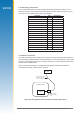
3.0 Packaging and delivery Jupiter 32 modules are shipped in Tape and Reel form. The reeled modules are shipped with 250 units per reel. Each reel is ‘dry’ packaged and vacuum sealed in an Moisture Barrier Bag (MBB) with two silica gel packs and placed in a carton. All packaging is ESD protective lined. The Jupiter 32 GPS receiver is a Moisture Sensitive Device (MSD) level 3. Please follow the MSD and ESD handling instructions on the labels of the MBB and exterior carton. See Figures 3-1, 3-2 and 3-3.
250 per reel 44mm 20.00 2.00 4.00 5 1.75 20.20 1. 44 2.0 Direction of Feed 3.2±0.10 13.30±0.10 0.35±0.05 All Dim in mm 17.3±0.10 Figure 3-3: Jupiter 32 Packaging LA000605D © 2007 Navman New Zealand. All rights reserved. Proprietary information and specifications subject to change without notice.
4.0 Manufacturing process recommendations The Jupiter 32 uses the latest Land Grid Array (LGA) technology. Solder interconnect is formed solely by solder paste applied to the board assembly. This results in a low stand-off height, depending on solder paste volume and Printed Circuit Board (PCB) geometry. This makes LGA ideal for small form-factor applications. Solder joint reliability studies indicate that LGA greatly exceed typical industry reliability. 4.
Pre-heat Reflow Heat 260 Cool-down Peak Temp. Liquidus Temp. Temperature oC Pb-free Solder Pb Solder Time Sec 0 300 Figure 4-1: Sample Lead and Lead free reflow profile 4.1.5 Coating The final PCB may be selectively coated with an acrylic resin, air / oven cured conformal coating, clear lacquer or corresponding method, which gives electrical insulation and sufficient resistance to corrosion. 4.1.
on the part. The proper nozzle should also heat the component leads by either hot gas or hot bar. The ideal reflow profile should be the same as the one used for mounting the part and depends upon the paste used. The reflow zone can be shortened as long as the reflow is complete. The part should then be lifted off automatically during the transition from reflow to cool down cycles using a vacuum. 4.1.
5.2.2 Push-to-Fix mode Unlike TricklePower, the operation in this mode is not cyclic. This mode always forces the GPS software to revert to a continuous sleep mode after a navigation position fix. It will stay in sleep mode until woken by wakeup input, and compute a fresh position. If the ephemeris data become invalid or new satellites come into view, the RTC has the ability to self activate and refresh the data, thus keeping the restart TTFF very short.
Errors Errors in message receipt (other than checksum errors) result in the response: $PTTK,ERROR,xx*CS where xx is a hexadecimal error code. Magnetic Variation (Declination) The Jupiter 32 module does not calculate the magnetic variation. 5.4 Navman proprietary NMEA low power mode messages Navman has added a number of proprietary NMEA input messages to configure the TricklePower and Push-To-Fix modes. 5.4.
5.5 Save and Retrieve Configuration Data to Flash The current settings of the Jupiter 32 will be stored in Flash memory upon a command from the user. Refer to Application Note LA000266. All parameters are written as a set.
5.6 Selectable User Profiles The purpose of this feature is to provide some typical application profiles which users can select through a simple NMEA message. These profiles are macro-like commands that modify parameters used for common applications. These profiles produce optimal navigation default settings which conform specifically to an application’s requirements. They can be then be saved using the Write-to-Flash feature. The new profile will not be written to Flash automatically.
6.0 Glossary and acronyms Axial ratio: For an electromagnetic wave having elliptical polarisation, the ratio of the magnitudes of the major axis and the minor axis of the ellipse described by the electric field vector. EMI: Electromagnetic Interference ENIG: Electroless Nickel Immersion Gold FR4 substrate: Flame Retardant type 4 The usual base material from which plated-through-hole and multi-layer printed circuit boards are constructed. The type ‘4’ indicates woven glass reinforced epoxy resin.
Push-To-Fix and TricklePower are registered trademarks of SiRF Technologies. © 2007 Navman New Zealand. All Rights Reserved. Information in this document is provided in connection with Navman New Zealand (‘Navman’) products. These materials are provided by Navman as a service to its customers and may be used for informational purposes only. Navman assumes no responsibility for errors or omissions in these materials.