SPEED 2100 Installation and Operation Manual w w w. n a v m a n . c o m English ............. 3 Français ......... 11 Español .......... 19 Deutsch .......... 27 Nederlands .... 35 Suomi ............. 43 Svenska .........
FCC Statement Note: This equipment has been tested and found to comply with the limits for a Class B digital device, pursuant to Part 15 of the FCC Rules. These limits are designed to provide reasonable protection against harmful interference in a normal installation. This equipment generates, uses and can radiate radio frequency energy and, if not installed and used in accordance with the instructions, may cause harmful interference to radio communications.
Contents 1 Operation ......................................................................................................... 4 Simulation ........................................................................................................ 4 Modes .............................................................................................................. 4 Trip Log reset ................................................................................................... 5 Total Log reset .............
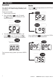
1 Operation Simulation Modes This feature demonstrates the operation of the instrument. In this mode the digits randomly count up and down. Press the key to toggle between the SPEED and TRIP LOG modes. To activate this mode: 1. Power up the instrument 2. Press and hold the Press for 15 Seconds Press for 15 Seconds / > / SPd key for 15 seconds is displayed. The display will start until counting randomly. 3.
Trip Log Reset Total Log Reset Select the TRIP LOG mode. Press and hold the key until the display resets to zero. Press and hold the and / keys while powering up and hold for at least 30 seconds until the TOTAL LOG is reset. Press and hold Press for 30 seconds 2 Instrument Setup The instrument must be calibrated after installation to ensure accurate speed readings. Selecting units of measure Information will now be indicated in the selected display unit.
3. Release both keys when the display shows the following: 4. If the temperature reading indicated is incorrect, press the key to increase the key to decrease the reading or the reading. 4. The TRIP LOG reading will reset to 0.0. 5. When the correct reading is indicated, press and hold the and keys again for two seconds. CAL 5. Travel a known distance. 6. If the display indicates a reading different from key to the known distance, press the key to increase the reading or the decrease the reading. 7.
3 Installation Location Mounting The SPEED 2100 is designed for above or below deck installation. Select a position that is: The instrument panel must be 3mm to 19mm (1/8” to 3/4”) in thickness. • On a flat surface • Drill a 51mm (2”) hole in the instrument panel. • At least 300mm (12”) from a compass • • At least 500mm (20”) from any radio Remove brackets and insert the instrument so the back is flush with the instrument panel.
Wiring Connection • Keep electrical and transducer cables away from alternator or other noise generating electrical cables. Avoid connecting the instrument to power circuits that share loads with ignition, alternators, inverters and radio transmitters. Electrical power supply connections should always be as short as possible. • Connect the red wire to the positive supply via a 1 amp fuse or a 1 amp circuit breaker. Connect the black wire to the electrical ground.
Appendix A - Specifications • Size Mount 51mm diameter hole Depth behind face plate 95mm max. Display 3-character LCD • Colour Black with texture on bezel. • Backlighting Red coloured diffused lighting for display. • Water Integrity Front will withstand direct water spray. • Impeller • Speed units and resolution 0-19.9 and then 20-50 in knots, MPH or KPH (depending on transducer type), • Trip Log 0-999 miles, non-volatile, resetable (0.00-9.99 read in hundredths, 10.0-99.
Appendix B - Troubleshooting Chart No display: 1. Check DC power connections and DC polarity with voltmeter. 2. Check fuse. No speed or log readings: Check and make sure that the paddlewheel on the impeller is not stuck or fouled with growth. Inaccurate speed readings: 1. Re-calibrate 2. Check paddlewheel Erratic speed readings while moving: 1. Check to make sure that the impeller is aligned fore and aft. 2. Review the installation for possible erratic water flow over the impeller.
Appendix C - How to contact us NORTH AMERICA ASIA e-mail: thonge@cscoms.com Website: www.plastimo.it NAVMAN USA INC. 18 Pine St. Ext. Nashua, NH 03060. Ph: +1 603 577 9600 e-mail: sales@navmanusa.com China Peaceful Marine Electronics Co. Ltd. Hong Kong, Guangzhou, Shanghai, Qindao, Dalian. E210, Huang Hua Gang Ke Mao Street, 81 Xian Lie Zhong Road, 510070 Guangzhou, China. Ph: +86 20 3869 8784 e-mail: sales@peaceful-marine.com Website: www.peaceful-marine.com Vietnam Haidang Co. Ltd.
Lon 174° 44.535’E SPEED 2100 Made in New Zealand MN000206A N AV M A N Lat 36° 48.