Pilot 3380 Tracker 5430/5430i C H A RA TU PT LO O P T I T L E O R T www.navman.
FCC Statement Note: This equipment has been tested and found to comply with the limits for a Class B digital device, pursuant to Part 15 of the FCC Rules. These limits are designed to provide reasonable protection against harmful interference in a normal installation. This equipment generates, uses and can radiate radio frequency energy and, if not installed and used in accordance with the instructions, may cause harmful interference to radio communications.
Contents 1 Introduction ..........................................................................................................................................6 1-1 Care . . . . . . . . . . . . . . . . . . . . . . . . . . . . . . . . . . . . . . . . . . . . . . . . . . . . . . . . . . . . . . . . . . . . . . . . . . . . . . 6 1-2 Plug-in cards . . . . . . . . . . . . . . . . . . . . . . . . . . . . . . . . . . . . . . . . . . . . . . . . . . . . . . . . . . . . . . . . . . . . .
11 User card display ................................................................................................................................ 25 12 About display ..................................................................................................................................... 26 13 Setup menu........................................................................................................................................ 26 13-1 System setup . . . . . . . . . . . . . . . . .
Important It is the owner's sole responsibility to install and use the instrument in a manner that will not cause accidents, personal injury or property damage. The user of this product is solely responsible for observing safe boating practices. Global Positioning System: The Global Positioning System (GPS) is operated by the US government which is solely responsible for its operation, accuracy and maintenance.
1 Introduction TRACKER chartplotters NAVMAN’s TRACKER chartplotters are compact, ruggedly built, highly integrated navigation instruments. They have been designed to be easy to use. Complex navigation functions can be performed with a few key presses, taking the hard work out of navigation. This manual covers these NAVMAN chartplotters: TRACKER 5430 Greyscale display, external GPS antenna. TRACKER 5430i Greyscale display, internal GPS antenna.
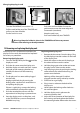
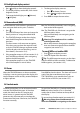
Changing the plug-in card Gold contacts under here 1 2 3 Card Holder Pull the card holder out of the TRACKER and pull any card out of holder. Push new card into holder. Ensure the gold contacts are on the outer edge and underneath (see above). Put the card in its case. Keep the card’s case. Turn the TRACKER off (see section 2-1). Push card holder fully into TRACKER Warning: Keep the holder in place in the TRACKER at all times to prevent moisture from entering card compartment.
2 Basic operation Overview of the keys ESC Go back to an earlier menu or display. Any changes are ignored. DISP Show a menu of the main TRACKER displays. To go to a display, select it from the menu (see section 2-2). , , , Cursor keys, to move the cursor or the selection highlight. MENU Show a menu of the options for the current display. Press MENU again to display the setup menu (see section 13).
2-1 Turning on and off / auto power 2 Auto power If the TRACKER is wired for auto power (see section 15-3), then the TRACKER automatically turns on and off with the boat power, and can not be turned on or off manually. If necessary, adjust the display to be easy to read (see section 2-3). Read the warning and press ENT. 3 The satellite display is shown. Either wait for the GPS receiver to start up and the status to change from ‘acquiring’ to ‘GPS fix’ (see section 7).
2-3 Backlight and display contrast 1 Press 2 The display and keys are backlit, with sixteen brightness levels. briefly to show the display controls. To change the backlight, press or (brighter) (dimmer) 3 4 To change the display contrast: i Press to choose Contrast. ii Press or to adjust the contrast. Press ENT to accept the new values. 2-4 Man overboard (MOB) The MOB feature saves the boat’s position and then navigates back to this point.
2-7 Navigating The TRACKER has two ways of navigating, going straight to a point or following a route. Enter waypoints at points of interest before starting to navigate (see section 9-2-1). Following a route A route is a list of waypoints that the boat can follow (see section 10). 1 To create waypoints before creating the route, use the waypoints display (see section 9-2-1). 2 To create a route, go to the chart or routes display (see section 10-2-1).
3-1 Chart display A typical chart display shows: Data display. To turn the data off or on or to change what data is displayed, see section 3-1-8. Compass display (see section 3-1-4). To turn the compass off or on, see section 3-1-8. The chart. To change the types of information displayed, (see section 13-2). Typical waypoint (see section 9). Boat position (see section 3-1-1) The cursor (see section 3-1-1).
36° 29.637' S 175° 09.165' E Degrees Latitude Longitude Minutes, to 3 decimal places (about 2 m (6 ft) resolution) If the cursor has been moved in the last ten seconds, then the position is the cursor’s position, and the latitude has a cursor symbol to show this: + 36° 29.684' S 175° 09.201' E Warning: When reading the boat position, make sure the position is not the cursor position. 3-1-3 Chart scale Press to zoom in and display a smaller area of the chart in more detail.
3 To choose the size of the numbers: i Select Size. b Press ENT to display a menu of the data that can be shown in the field. ii c Select: Small: displays three fields per line and up to four lines. iii Repeat the above step to set the other data fields. Press ESC. Medium/Large: displays two fields per line and up to four lines. 4 Tip: If less than four lines are used, the numeric data will take up less of the chart area. To change the data display: i Select Data setup.
3-4 Projected course If Projected course is turned on, then the TRACKER will display the projected position based on the course over ground (COG), speed and a specified time. To turn Projected course on and off and to set the time, see section 13-2. Projected position Boat’s projected course Boat position 3-5 Tracks and tracking Tracking records the boat’s position to memory at regular intervals, which can be: Time intervals. Or distance intervals.
4 Fuel display To use the fuel display, the optional fuel kit must be installed and the fuel data set up (see section 13-4). To go to the fuel display, press DISP and select Fuel. The fuel display shows: Used: The total fuel used since it was reset to 0 by the Clear Used command (see section 13-4). Remaining: The amount of fuel remaining in the fuel tank(s). Flow: The fuel consumption. For twin engine installations, the fuel flow for each engine is shown separately.
5 Data display The data display has six large numeric data fields. To go to the data display, press DISP and select Data. Change what data is displayed 1 Press MENU and select Data setup. 2 Change a data field: i Press the cursor keys to highlight the field. ii Press ENT to display a menu of the data that can be shown in the field. iii Select the data to show in the field; select None to leave the field empty. 3 Repeat the above step to change other fields.
Change the numeric data display 1 In the highway display, press MENU and select Data setup. 2 Change a data field: i Press the cursor keys to highlight the field. ii Press ENT to display a menu of the data that can be shown in the field. iii Select the data to show in the field; select None to leave the field empty. 3 Repeat the above step to change other fields. 4 Finally, press ESC to return to the highway display. 7 Satellites GPS worldwide navigation The US Government operates the GPS system.
7-1 Satellite display The satellite display has information about the GPS satellites and GPS position. To go to the satellite display, press DISP and select Satellite. When the TRACKER is turned on, the satellite display is shown automatically while the GPS antenna starts up. The satellite display shows: Status of GPS antenna, for example Acquiring, GPS fix, No GPS. If the unit is in Simulate mode it displays Simulate (see section 2-6). Time & date from GPS satellites.
The tides display shows data for the chosen date: Tide station name Distance from boat Moon phase for moon at the current time on the chosen date. Current time Chosen date for display Tide chart Night Night Dawn Dusk Day Day Tide height cursor. Press or to move cursor up and down. Height of cursor. Tide height Time of day, 0 to 24 hrs Time cursor. or to move cursor sideways. Time of cursor Tide height at that time. Press Times on selected date.
If there are many waypoints, use this feature to select which waypoints are displayed on the chart. Note: the other choices for the “Waypoints” setup option are “Hide all” (no waypoints are displayed on the chart) and “Show all” (all the waypoints are displayed on the chart) (see section 13-2). 9-1 Waypoints display To go to the waypoints display, press DISP and select Waypoints (see right).
3 Change the waypoint data (see section 9-2-7). Select Save. Editing a waypoint from the waypoints display 1 In the waypoints display, press or to Deleting a waypoint from the chart display 1 In the chart display, move the cursor to the waypoint to delete. 2 Press MENU and select Delete. 3 Select Yes to confirm. highlight the waypoint to edit. Press MENU and select Edit. Deleting a waypoint from the waypoints display Change the waypoint data (see section 9-2-7). Select Save.
10-2 Managing routes Warning: After creating or changing a route, display the route on the chart and check that it does not cross land or dangerous water. 6 A. Creating a new route from the chart display 8 The legs of a route must start and end at waypoints. If a leg does not start or end at an existing waypoint then a new waypoint will be created automatically (to change the new waypoint data, see section 9-2-7). 1 In the chart display, press MENU and select New route.
4 2 The selected route is displayed on the chart, with a circle around the first waypoint. To insert the first waypoint in a new route, select Leg 1. 3 Edit the route as described in section 10-2-1 A, starting at step 4. To insert a waypoint at the end of the route, select the unused leg at the end of the list of waypoints.
11 User card display A C-MAP™ user card is an optional plug-in card that can store data files (see section 1-2). There are three types of files: waypoints, routes or a track. Note: The older 5 volt cards are not supported. To go to the user card display, press DISP and select User card. The user card display has: File list A list of the files on any user card in the TRACKER. Waypts, Routes The number of waypoints and routes currently in the TRACKER.
Deleting a file from the user card 1 2 3 Select the file to delete. Press MENU and select Delete. Select Yes to confirm. Reading the file information This reads the file names from the user card and displays them. Reading does not load any file data into the TRACKER. 1 2 Press MENU and select Card. Select Read. Formatting the user card Formatting prepares a user card for use. Format the card if there is an error message saying that the card is not formatted. Any data files on the card are deleted.
Setup menu map, with factory default settings in brackets System Rotation (North up) Projected course (Off ) CDI scale (0.1 nm) Plotter mode (Off ) Map datum (WGS84) NMEA datum offset (Off ) Map shift (None) Waypoints (Selected) Anticlutter (Off ) Lat.
13-1 System setup Language Factory reset Select the language for the displays. The options are English, Italian, French, German, Spanish, Dutch, Swedish, Portuguese Finnish and Greek. Backlight Resets all the TRACKER setup menu data back to the factory default settings as shown on the setup menu map. Any waypoints, routes or tracks are not deleted. Select the backlight intensity and the LCD contrast levels.
Map datum and map shift Satellite derived positions on the TRACKER are based on a worldwide reference (datum) known as WGS84. Most paper charts are based on WGS84. However, some paper charts are not based on WGS84, which results in an offset between a position on the TRACKER and the same position plotted on the paper chart. To match the TRACKER’s positions with a local chart that is not based on WGS84: Either select Map datum and select the datum for the local chart.
13-3 GPS setup GPS Source There are three options: • Internal: For the TRACKER 5430i, use the internal GPS antenna and receiver. For TRACKER 5430, use the internal GPS receiver and an external GPS antenna plugged into the gold connector on the TRACKER. • NMEA: Use an external GPS or DGPS source connected via NMEA (see section 14). • NavBus: Use an external GPS or DGPS source connected via NavBus (see section 14). DGPS Source Enables or disables the satellite based DGPS correction (see section 7).
Fuel Cal Without calibration the error in fuel measurements can be up to ± 10%. Calibration can reduce the error substantially. For twin engine installations calibration of each transducer is required. Calibrating the fuel transducer requires accurate measurement of the fuel used. This is easiest with a small portable tank. It should be noted that due to air pockets, it is very difficult to fill underfloor tanks to the same level twice.
13-6 Logs setup The values can be changed independently of each other. These log values are saved when the unit is turned off. The TRACKER has two distance logs. Trip distance: The distance travelled since log was reset. Total distance: The distance travelled since total log was reset. Reset trip dist This resets the trip distance to zero. Reset total dist This option resets the total distance to zero. 13-7 Alarms setup For alarm operation, see section 2-5.
13-8 Units setup Distance units Options are nm (nautical miles), mi (statute miles) or km (kilometres). Speed units Options are kn (knots), mph (miles per hour) or kph (kilometres per hour). Fuel units Options are litres, US gal (US gallons) or Imp gal (Imperial gallons). Compass The options are °T (True north) or °M (Magnetic north). Depth units Options are ft (feet), fm (fathoms) or m (metres). 13-9 Comms setup NMEA out Disable or enable the NMEA output to an autopilot or other instrument.
Demo Simulates the boat moving along a route at a given speed. When it reaches one end it retraces the route in the other direction. Before setting this mode enter at least one route (see section 10-2-1). The options are: 2 In the Simulate setup menu, select Simulate and turn it on. 3 Select Mode and set it to Normal or Demo. 4 Select and enter the other data required for simulate: Normal requires Speed and Heading. Speed: The simulated boat speed to use. Demo requires Speed and Route.
15 Installation Correct installation is critical to the performance of the unit. There are two components to install, the TRACKER and a GPS antenna. In addition, install the optional fuel kit to use the TRACKER as a fuel computer. The TRACKER can: Drive external beepers or lights for the alarm. Send and receive data from other NAVMAN instruments connected via NavBus. The backlight setting is shared (see section 14). Send NMEA data to an autopilot or other instrument.
15-3 Installation For bracket mounting: Warning: Ensure that any cut holes will not weaken the boat. If in doubt, consult a qualified boat builder or marine engineer. Display unit 1 i Hold the bracket in place and mark the screw holes. ii Drill the screw holes and screw the bracket in place with the screws provided. Do not overtighten the screws or the display unit might not rotate. Do not fit the display unit yet.
• • Either Basic wiring: When the main switch is on, the TRACKER must be powered on manually with the key. The engine hours counter and fuel counter are disabled. Or Auto power wiring: The TRACKER turns on and off automatically when the ignition is turned on and off (see section 2-1). The engine hours counter and fuel counter are enabled. Choose auto power when the optional fuel kit is fitted. 5 Remove the dust cover. Turn the TRACKER on (see section 2-1).
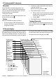
Installation Basic Wiring Power/data cable (black locking collar) This option is possible on the TRACKER 5430. Pin Wire Black wire: Connect this to the negative battery terminal. 1 2 3 4 5 6 7 8 Signal Black Ground (power negative, NMEA) Note: The cable has two wires with black coverings, the black wire (pin 1) and the shield (covered with heatshrink). These wires are connected within the cable and therefore it does not matter which black wire you use.
Appendix A - Specifications 140 chart datums (see below). Physical Size 126 mm H x 126 mm W x 64.8 mm D (5.0" x 5.0" x 2.57"). TRACKER 5430, 5430i: greyscale, (240 x 360 pixels). One user-defined map shift. Chart scale 0.05 to 4096 nm for chart (chart dependent) down to 0.01 nm in plotter mode. Fuel Computer (Optional fuel transducer required) Electrical Power supply 8 to 16 V DC, 220 mA with full backlight. Outboard carburetted two stroke petrol/ gasoline engines: 50 to 300 hp.
List of datums ADINDAN ARC 1950 ASCENS.ISL.58 BISSAU CAPE DABOLA EUROPEAN 1950 GRACIOSA BASE HJORSEY 1955 IGN72 IRELAND 1965 KERTAU 1948 LUZON MIDWAY AS. 61 NAD 1983 O.S. IRELAND P.TE NOIRE 48 POTSDAM QORNOQ S.LEONE 1960 SELVAGEM 1938 TANANARIVE 25 VOIROL 1960 YACARE AFGOOYE ARC 1960 AUS.GEOD. 66 BOGOTA OBS. CARTHAGE DECEPTION IS EUROPEAN 1979 GUAM 1963 HONG KONG 63 INDIAN ISTS 73 AS.69 KUSAIE AS. 51 M. MERCURY 68 MINNA NAHRWAN O.S.G.B. 1936 P.TO SANTO 36 PRV.S.AMER.56 REUNION S.
b The normal error in GPS position will exceed 10 m (33 ft) for about 5% of the time. c Under special circumstances the US Department of Defence may introduce a deliberate and changing error in the GPS positions of up to 300 m (1000 ft). 7 No DGPS fix or loss of DGPS fix: a 13 Fuel Used or Remaining seem wrong: a The engine has been run while the TRACKER is turned off and it has not recorded the fuel use. Wire the auto power option (see section 15-3).
Appendix C - Glossary and navigation data Glossary Attention Area - An important area on a chart, such as a restricted anchorage or a shallow area (see section 13-2). Bathymetric line - A depth contour line on the chart. MOB - Man overboard. MOB function - Starts navigating back to the place where someone fell overboard (see section 2-4). Chart card - A plug-in card that stores chart data for a region (see section 1-2).
Navigation data The boat is sailing from the start to the destination and has moved off the plotted course from the start to the destination. BRG Bearing to Destination Bearing to the destination from the boat. +BRG Bearing to cursor Bearing to cursor from boat (cursor mode, see section 3-1-1). CDI Course Deviation Indicator When the boat is navigating to a point, the chart and highway displays show a parallel line on either side of the plotted course.
Lon 174° 44.535’E Lat 36° 48.