PeakTech® 1340 - 1375 Operating instructions 2 CH & 4 CH Digital Memory Oscilloscopes
Table of contents 1. Safety instructions............................................................................................................................. 3 2. Safety symbols .................................................................................................................................. 5 3. Quick guide ........................................................................................................................................ 6 Structure of the oscilloscope..........
Amplitude settings ................................................................................................................................... 73 Offset settings ..........................................................................................................................................73 High Level Setting.................................................................................................................................... 73 Low Level Setting..............................
1. safety instructions for operating the appliance This product complies with the requirements of the following European Union Directives for CE conformity: 2014/30/EU (Electromagnetic Compatibility), 2014/35/EU (Low Voltage), 2011/65/EU (RoHS). Overvoltage category II; pollution degree 2. To ensure the operational safety of the unit and to avoid serious injuries due to current or voltage surges or short circuits, it is essential to observe the following safety instructions when operating the unit.
Warning: If the oscilloscope is connected to an input signal greater than 42V peak (30Vrms) or circuits greater than 4800VA, please follow the instructions below to avoid fire or electric shock: -Use only insulated probes and test leads. -Inspect all accessories before use and replace if damaged. If in doubt, do not take measurements. -Remove the USB cable connecting the oscilloscope to the computer. Never exceed the maximum specified input voltages.
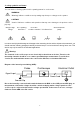
2. safety symbols and terms You can find the following symbols in this operating manual or on the meter. WARNING! "Warning" indicates conditions and operating steps that pose a danger to the operator. CAUTION! "Caution" indicates conditions and operations that may cause damage to the product or other property.
3.
F1 F2 F3 F4 F5 H1 H2 H3 H4 H5 Function keys Switch off left/right menu Right display menu Lower display menu -7-
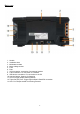
Back cover 1. Handle 2. Ventilation slots 3. Multimeter sockets 4. Mains voltage socket 5. Fuse 6. Feet 7. VGA connection: connection of an external monitor 8. LAN connection: For connection to a network 9. USB device connection: For connection to the PC 10. Anti-theft device: Opening for fastening 11. AV Port: Signal output socket (optional) 12. Triger Out (P/F) Port: Trigger signal output & Pass/Fail connection 13.
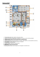
Controls 2-channel 1. Function key area: Main control for all function menus 2. Additional functions (depending on model): Menu keys e.g. for the function generator 3. Trigger control: Rotary knob and menu buttons for trigger control 4. Horizontal range: Rotary and push buttons for the horizontal range 5. Vertical range: Rotary and push buttons for channel 1 and channel 2, as well as MATH function key 6. Reset button: Resets measurement function to standard 7. Print button: Prints screenshot 8.
Controls 4-channel 1. 2. 3. 4. 5. 6. 7. 8. Function key area: Main control for all function menus Additional functions (depending on model): Menu keys e.g.
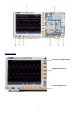
Introduction to user control Example: 2 channel model 1. Waveform display area 2. RUN/STOP: Can also be used via touch screen 3. Trigger status 4. Activate touch screen function menu 5. Blue line shows cursor position A and B (only with cursor measurement) 6. The [T] mark shows the horizontal trigger position 7. Displays the trigger position in the memory length 8. Shows the current trigger value and the location in the internal memory 9. Lock touch screen operation ( ) / enable ( ) 10.
Testing before commissioning It is recommended that after receiving a new oscilloscope, a check of the unit is carried out as follows: 1. check if the unit has been damaged during transport. If you find that the cardboard packaging or the protective foam pads are badly damaged, save them until the entire unit and its accessories have passed the electrical and mechanical test. 2. checking the accessories The accessories supplied are described in Appendix B "Accessories" of this manual.
Probe compensation When you connect the probe to an input channel for the first time, you must adapt the probe to the input channel. An uncompensated or incorrectly compensated probe will result in measurement errors. Perform the probe compensation as follows: 1. Set the damping factor of the probe to 10X in the menu, also set the switch on the probe to 10X and connect the probe to channel 1. When using the hook tip, make sure that it remains securely connected to the probe.
Setting the probe damping factor The probe has several probe damping factors that affect the vertical scaling factor of the oscilloscope. If the set probe attenuation factor is to be changed or checked, press the function menu key for the respective channel and then the selection key corresponding to the probe until the correct value is displayed. This setting remains valid until it is changed again. Note: The damping factor of the probe in the menu is preset to 10X at the factory.
Self-calibration With the auto-calibration, the oscilloscope can be quickly set to the optimum state for highly accurate measurements. You can run this programme at any time, but you must do so if the ambient temperature varies by more than 5°C. Remove all probes and cables from the input sockets before performing the auto-calibration. Press the "UTILITY" button, then the "H1" button to enter the FUNCTION menu; turn the "Multipurpose" knob to select "Adjust".
Set the vertical offset to 0 again: Turn the VERTICAL POSITION knob to change the vertical position of the channel and press the VERTICAL POSITION knob to reset the vertical position to 0. This is especially useful if the position track goes far out of the display area and the signal should immediately reappear in the centre of the screen. 2. Change the vertical setting and observe the resulting change in status information.
Introduction to the Trigger System Picture 0-12 shows a setting knob and three buttons for the TRIGGER CONTROL. The following exercises will familiarise you step by step with the settings for the trigger system. Trigger control panel Press the "Trigger MENU" trigger settings. button to open the Trigger menu. Use the 5 menu items to change the Use the "TRIG" adjustment knob to change the trigger level settings.
Press repeatedly to switch options Scroll through the list: If there is a scroll bar in the left menu or in the file system window, you can "swipe" up and down to scroll through the list. Touchable menu windows: Tap on the symbol and a menu window is displayed in the upper left edge of the display area. Tapping on the menu item with your finger has the same function as pressing the corresponding key.
Gesture control in normal mode Select a channel (CH1 to CH4 button): Press the pointer (yellow/blue) belonging to the channel on the left side of the display. Set the trigger level (trigger level rotary knob): "Swipe" at the pointer (yellow/blue) belonging to the channel on the right side of the display. Adjust the horizontal position (Horizontal Position knob): "Swipe" left/right in the display.
Double and single zoom If Double-Zoom is selected in the touchscreen menu window ( ), you can change the time base in the display area by a horizontal swiping movement and the voltage division of the current channel by a vertical swiping movement: - 20 -
If you select Single Zoom, a control panel for these functions appears when you touch any point in the main window: Set Voltage/Division (Vertical Scale knob): Tap the upper left field of the displayed Single Zoom menu to change the Volt/Div of CH1 (yellow) or the lower left field to decrease it. For CH2, perform this operation in the right fields.
Gesture control in Wave Zoom mode Press the HOR button to switch to zoom mode. The upper half of the display shows the main window and the lower half shows the zoom mode. Zoom mode is the enlarged display of the main window.
Swipe right/left in the centre of the zoom window to change the horizontal position. Changing Horizontal/Vertical Settings in Double Zoom Mode In the zoom window, swipe left/right simultaneously to change horizontal time base and swipe up/down simultaneously to change vertical volt/division.
Changing Horizontal/Vertical Settings in Single Zoom Mode Tap in the zoom window to open the menu, then tap the corresponding Tap the icon to change the associated value.
Run/Stop: Double-tap the display area or select the corresponding icons waveform display. Touch Keyboard: To enter words, e.g. when naming files, you can use the keyboard that appears: Set menu value: In some menus there are sliders for different values.
4. User instructions (for advanced users) In the preceding paragraphs, the user has already been familiarised with the basic functions of the function areas, keys and buttons on the front panel of the oscilloscope. Based on the introduction of the previous chapter, the user should already have gained first insights into changing the oscilloscope settings, selecting and evaluating the status bars and general operation.
Adjust vertical system The VERTICAL functions include 5 menu buttons such as CH1 ~ CH2 (2CH models) and Math, and 8 rotary controls such as VERTICAL POSITION, VOLTS/DIV for each measuring channel. Settings CH1 ~ CH2 Each channel has an independent vertical menu with functions based on that channel. Switch waveform display on/off (CH & Math function) Pressing the CH1 ~ CH2 or Math buttons has the following effect: - If the waveform is switched off, it is switched on and the channel menu is displayed.
1. Set channel coupling For example, to represent channel 1 with a square wave signal on a DC coupling basis, proceed as follows: (1) Press the CH1 button to display the channel menu. (2) Select Coupling in the lower menu. (3) Select DC in the right-hand menu. DC and AC components are thus recorded. (4) Alternatively, select AC in the right-hand menu. DC components are now blocked. 2.
Mathematical function The mathematical functions are used to display measuring channels added, subtracted, multiplied or divided. Alternatively, the FFT function can be activated.
User defined function Press the Math button to display the Math menu below. Select User Function in the bottom menu, an expression input keyboard appears. 3. create a representation. When you are finished, select on the keyboard to confirm. The division of the Math waveform is displayed at the bottom left of the screen. FFT function The FFT (Fast Fourier Transformation) function converts a time-based waveform into its individual frequency components.
Select FFT window ■ There are six FFT windows. Each window makes trade-offs between frequency resolution and amplitude accuracy. Choose the window based on what you want to measure and the characteristics of your source signal. The following table will help you choose the best window: Art Rectangle (Rectangle) Hanning Characteristics This window is best for frequency resolutions, but is the worst for accurately measuring the amplitude of these frequencies.
Notes for FFT use The waveform zoom function also works for FFT. Use the dBV RMS scale for a detailed view of multiple frequencies, even if they have different amplitudes. Use the linear RMS scale to compare all frequencies in an overall view. Signals that contain a DC component or offset can lead to incorrect FFT signal amplitude values. To minimise the DC component for the source signal, select AC coupling.
Set horizontal system The HORIZONTAL CONTROLS consist of the HORIZ-MENU button and adjustment knobs such as HORIZONTAL POSITION and SEC/DIV. 1. adjustment knob HORIZONTAL POSITION: with this adjustment knob you control the horizontal positions of all channels (including those created by mathematical calculation) whose resolution changes with the time base. 2. setting knob SEC/DIV: with this you set the horizontal scale factor with which you determine the main time base or window. 3.
Set trigger system The trigger determines when the oscilloscope starts acquiring data and displaying the waveform. Once set correctly, the trigger can convert a fluctuating display into a meaningful waveform. When the oscilloscope starts acquiring data, it records enough data to display the waveform to the left of the trigger point. The oscilloscope continues to record data while waiting for a trigger condition.
Trigger Brief description The single, logic and bus trigger menus are described below: Edge trigger: Occurs when the trigger input passes through a specific voltage level with the specified slope. Video Trigger: Trigger on fields or lines for a standard video signal. Slope Trigger: The oscilloscope starts triggering according to the rate of rise or fall of the signal. Pulse Trigger: Finds pulses with specific widths.
Detailed trigger description: 1. edge trigger (edge) An edge trigger occurs at the trigger threshold of the input signal. Select the edge trigger mode to trigger on the rising or falling edge of the signal. Edge Trigger menu: Menu Trigger Mode Source Coupling Gradient Mode & Holdoff Setting Description Flank Set vertical trigger type as edge triggering CH1 CH2 EXT EXT/5 AC Line AC DC Rising Falling Car Normal Single Holdoff Channel 1 as trigger signal. Channel 2 as trigger signal.
2. video trigger Select the video mode to trigger on video fields or video lines of NTSC, PAL or SECAM standard video signals. In video trigger mode, the setting information is displayed at the bottom right of the screen, e.g.: indicates that video trigger on CH1 and sync type "even" has been selected. Video trigger menu: Menu Trigger Mode Source Modu Sync Fashion Holdoff Setting Video CH1 CH2 EXT EXT/5 NTSC PAL SECAM Line Field Odd Even Line NO.
4. pulse width trigger The pulse trigger lets the oscilloscope trigger according to the pulse width of the signal. Unusual signals can be detected by adjusting the pulse width conditions. In pulse trigger mode, the setting information is displayed at the bottom right of the screen, e.g.: indicates that pulse trigger on CH1 with DC coupling has been selected and the polarity is positive and the trigger level is 0.00mV.
Runt Trigger Menu: Menu Trigger mode Source Threshold Setting Runt CH1 CH2 Up Level Low Level Polarity Description Set Vertical Trigger Type as Runt Triggering Channel 1 as trigger signal. Channel 2 as trigger signal. Select the level setting with the Multi ( ) rotary knob or tap +/- via touch screen for threshold setting Positive polarity: The unit triggers on the positive runt pulse. Negative polarity: The unit triggers on the negative runt pulse.
Windows Trigger Provides a high and a low trigger level, whereby the oscilloscope triggers when a signal passes through the high or low trigger level. In Windows trigger mode, the setting information is displayed at the bottom right of the screen, e.g.: indicates that the Windows trigger on CH1 has been selected with positive polarity and the difference between the up-level and low-level threshold is 0.00mV.
7. timeout trigger The unit triggers when the time interval (from when the rising edge (or falling edge) passes through the trigger level to when the adjacent rising or falling edge passes through the trigger level) is greater than the set timeout time. In timeout trigger mode, the setting information is displayed at the bottom right of the screen, e.g.: indicates that the timeout trigger on CH1 has been selected with positive polarity and the up-level and low-level threshold is 0.00mV.
8 Nth Edge Trigger The oscilloscope triggers on the Nth edge that appears after a specified idle time. As shown in the diagram, the unit shall trigger on the second falling edge after the specified idle time P1/P2/P3/P4M, where M, P1,P2,P3 and P4 are positive or negative pulse widths that are included in the count. In Nth edge trigger mode, the setting information is displayed at the bottom right of the screen, e.g.
Logic Trigger Trigger regarding the logic relation. In logic trigger mode, the setting information is displayed at the bottom right of the screen, e.g.: indicates that the trigger is in logic mode AND, CH1 is 2.00V as high trigger level and CH2 is 0.00mV as low trigger level.
Bus Trigger 1. SPI Trigger on specified data when timeout conditions are met. When using the SPI trigger, SCL and SDA data must be specified. In SPI trigger mode, the setting information is displayed at the bottom right of the screen, e.g.: indicates that the trigger is in SPI mode, CH1 as trigger level is 0.00mV and CH2 as trigger level is 0.00mV.
2. I2C trigger The I2C Serial Bus consists of SCL and SDA. The transmission rate is determined by SCL and the transmission data by SDA. As shown in the picture, the oscilloscope can be triggered to Start, Restart, Stop, Ack Lost, a specific device address or a data value. In I2C trigger mode, the setting information is displayed at the bottom right of the screen, e.g.: indicates that the trigger is in I2C mode, CH1 as trigger level is 0.00mV and CH2 as trigger level is 0.00mV.
3. RS232 trigger RS232 is a serial communication type used for data transmission between PC and terminal. A character is transmitted as a frame of data consisting of 1 start bit, 5-8 data bits, 1 check bit and 1-2 stop bits. In RS232 trigger mode, the setting information is displayed at the bottom right of the screen, e.g.: indicates that the trigger is in RS232 mode and the trigger level of CH1 is 0.00mV.
4. CAN bus trigger CAN (Controller Area Network) is a serial communication protocol of the international ISO standardisation. When using the CAN bus trigger, you can trigger on Frame Start, Frame Type, Identifier, Data, ID & Data, Frame End, Missing Acknowledgement or Bit Fill Error. You must specify the signal source, trigger signal type, sample point and signal rate of the CAN signal. In CAN bus trigger mode, the trigger setting information is displayed at the bottom right of the screen, e.g.
Data End M-knob and arrow keys for selection Triggers on end frame of the data frame Missing Ack Triggers on missing ack (good message) Bit Stuffing Triggers on Bit-Stuffing Error Fashion Car Capture waveform even without trigger Holdoff Normal Capture waveform with trigger Single Capture waveform with trigger, then stop Operating the function menu The operating area of the function menu comprises 8 function menu keys: Measure, Acquire, Utility, Autoscale, Save, Display and Help, as well as 3 i
The interpolation method is a processing method to connect the sampled points, using some points to calculate the whole appearance of the waveform. Select the appropriate interpolation method according to the actual signal. Sine (x) / x-interpolation: Connect the sampled points with curved lines. Linear interpolation: Connect the sampled points with straight lines. This method is suitable for reconstructing the straight-line signals, such as the square wave or pulse wave.
Display menu Settings (in Acquire) Press the Acquire button; select Wave Display, XY Mode or Cymometer as the setting. Description of the Acquire menu: Menu Type Persist XY Fashion Counter Clear Setting Dots Vect Time OFF 1 sec. 2 sec. 5 sec. Infinity ON OFF ON OFF Description Only the sample points of the waveform are displayed. The space between the sampling points is connected with a line. Persist adjusts the afterglow of the waveform. Use the multi-rotary control ( ) to change the value settings.
XY Mode: XY mode is used to display the amplitude from one waveform against the amplitude from another. The data point from the first waveform sets the horizontal position, while the corresponding data point from the second waveform shows the vertical position for each point. The oscilloscope is in untriggered sampling mode: the data is displayed as bright dots.
Save and recall waveform Press the Save button to open the Save menu at the bottom of the screen. Here you can save waveforms, configurations, screenshots or record waveforms as a movie.
Waveform recording The oscilloscope can store 100 waveforms, which can be displayed again simultaneously with the current waveform. The recalled waveform cannot be adjusted subsequently, but remains in the form in which it was recorded. For example, to save a waveform from CH1 to memory address 1, proceed as follows: 1. Press the Save button 2. Save: Select Type in the lower menu and use the M-rotary knob to go to Wave in the left menu. 3.
System's own function for formatting 1. Connect the USB stick to the PC. 2. Right-click on Computer Manage (Win7) or right-click on the Windows icon Disk Management. 3. In the Disk Management menu you will find all the information about the connected data carriers, Select the USB storage device as marked in red in the following example 1 and 2: (Win10) and then on 4. Right-click on the area marked in red and select Format and a warning message appears, which you confirm with YES. 5.
7. Check that the formatting has been carried out and that FAT32 is now displayed with a cluster size of 4096. Cloning a waveform To clone a waveform that lies between the cursors, please refer to Appendix C. Saving and playing back recordings Waveform recording can record the current waveform and save it as a movie. You can set the interval between 1ms and 1000s, with a maximum of 1000 frames recorded. You can save the recording internally or externally.
Menu Playback Mode Frame Set Setting Start Frame End Frame Cur Frame Interval Play Mode Operate Loop Once Play Stop Description Turn the M-rotary knob to set the number of the start recording frame (1-1000). Turn the M-rotary knob to set the number of the end recording frame (1-1000). Turn the M-rotary knob to set the number of the current recording frame (1-1000).
The Record menu (external memory) is displayed as follows: Menu Fashion Record mode FrameSet Setting OFF Record End Frame Interval Refresh Operate Infinity ON OFF Play Stop Description Closes shaft form receptacle Sets recording menu Turn the M-rotary knob to set the number of the end recording frame (1-1000).
Set additional system functions Config Press the Utility button and select Function in the lower screen menu, then select Configure in the left menu. The configuration menu is displayed as follows: Menu Language Setting Chinese Description Sets the system language. The selectable languages may vary with different firmware versions.
Self-Calibration Self-calibration can help to achieve a better measurement result in the event of faulty measurement or a large influence of ambient temperatures. If the ambient temperature increases significantly (over 5°C), selfcalibration should always be carried out to achieve the best possible accuracy. Before performing a self-calibration, remove all probes from the terminals of the unit. Press the Utility button, then select Function from the lower menu and then Adjust.
4. Set output type: Select Output in the lower menu to make the output settings. Use one/two of the following options: "Pass", "Fail" or "Beep". Pass" and "Fail" are mutually exclusive options that cannot be activated at the same time. "Stop" means the unit stops when the set conditions are successfully met. 5. Begin to test: Select Operate in the lower menu, then Operate in the right menu as Start so that the test begins. 6. Save Rule: Select SaveRule in the lower menu.
Automatic measuring functions Press the Measure button to switch to the menu for the automatic measurement functions. The oscilloscope has 30 parameters for automatic measurement such as: Period, Frequency, Mean, PK-PK, RMS, Max, Min, Top, Base, Amplitude, Overshoot,Preshoot, Rise Time, Fall Time, +PulseWidth, PulseWidth, +Duty Cycle, -Duty Cycle, Delay A→B , Delay A→B , Cycle RMS, Cursor RMS, Screen Duty, Phase, +PulseCount, -PulseCount, RiseEdgeCnt, FallEdgeCnt, Area, and Cycle Area....
Automatic measurement of the voltage parameters The oscilloscope provides automatic voltage measurements including Vpp, Vmax, Vmin, Vavg, Vamp, Vrms, Vtop, Vbase, Overshoot and Preshoot. The image below shows a pulse with some voltage measurement points. Overshoot Max Vtop PK-PK Vamp Vbase Min . Preshoot Mean: Arithmetic mean value over the entire waveform. PK-PK: Peak-to-peak tension. Max: Maximum amplitude. The highest positive peak voltage measured over the entire curve. Min: Minimum amplitude.
Automatic measurement of the time parameters The oscilloscope provides automatic measurements of time parameters including Frequency, Period, Rise Time, Fall Time, +Width, -Width, Delay A→B , Delay A→B and Duty Cycle. The following picture shows a pulse with some timing points: Fall Time Rise Time +Width -Width Rise Time: The time it takes for the leading edge of the first pulse in the curve to rise from 10% to 90% of its amplitude.
Cursor measurements Press the cursor key to switch on a cursor and show it in the display. Press the key again to switch the cursor off.
Auto Cursor With the Auto Cursor setting, the horizontal cursor is set at the intersections of the vertical cursors with the waveform. Move the cursors with gesture control Please read the article "Other Touchscreen Settings".
Cursor measurements in FFT mode: In FFT mode, press the cursor key to open the cursor menu.
Press Autoscale to display the following menu: Menu AutoScale Fashion Setting ON OFF Description Switching on the autoscale function. Switch off the autoscale function. Track and adjust both vertical and horizontal settings. Track and adjust horizontal scale only. Track and adjust vertical scale only. Display waveforms with multiple periods. Wave Show only one or two periods. To measure the autoscale signal: Press the Autoscale button. The function menu is displayed.
Help function 1. Press the Help button and the overview appears. 2. Press Prev Page or Next Page to scroll through the help topics or use the M-rotary knob and the touch screen function to select. 3. Press OK if you want to view details of the theme. 4. Select Quit to leave the help menu again. Executing keys The executing keys are AUTOSET, RUN/STOP, SINGLE and COPY. Autoset This key is used to automatically set all the control values of the unit needed to generate a viewable waveform.
Evaluate waveform via autoset 5 types: Sine, Square, Video Signal, DC Level, Unknown Signal The corresponding menus are shown below: Sine (Multi-Period, Single-Period, FFT, Cancel Autoset) Rectangle (Multi-Period, Single-Period, Rising Edge, Falling Edge, Cancel Autoset) Video Signal: DC Level, Unknown Signal: Description of the icons: Multi Period: Displays several periods at the same time Single Period: Displays one period FFT: Switches to FFT mode Rising Edge: Shows rising edge of the waveform
Print screenshot To print a screenshot directly, proceed as follows: 1. Connect a printer to the USB device port on the back of the unit. Note: The printer must have PictBridge compatible drivers. 2. Press the Utility button and select Output under Function. 3. In the lower picture menu under Device, select Pict. (If the PC option is selected, you can transfer a screenshot to the PC). 4.
5. arbitrary function generator The oscilloscope has an integrated single-channel arbitrary function generator with 25 MHz. The generator provides 4 basic waveforms (sine, square, ramp and pulse), as well as 46 integrated arbitrary waveforms (e.g. noise, exponential rise, exponential fall, sin(x)/x, stair step). You can also create your own waveforms and save them internally or externally on USB. Connection Press the Utility button, then Function in the lower menu.
Sine signal The parameters of the sine signal in the right menu are: Frequency/Period, Amplitude/High Level, Offset/Low Level. Frequency settings Set the Frequency in the right menu (if Frequency is not displayed, select Period and press this button again to switch back to Frequency). To set the parameters in the right-hand menu, proceed as follows: There are three ways to change the parameters: 1. M-rotary knob: Turn the M-rotary knob to change the value of the current cursor position.
Period setting Select Period from the right-hand menu (if Period is not displayed, select Frequency and then press this button again to switch back to Period). Amplitude setting Select Amplitude in the right-hand menu (if Amplitude is not displayed, select High Level and then press this button again to switch back to Amplitude). Offset settings Select Offset in the right-hand menu (if Offset is not displayed, select Low Level and then press this button again to switch back to Offset).
Duty cycle setting Select Duty Cycle in the right menu of the pulse waveform, then set the parameters in the right menu. (If Duty Cycle is not displayed, select Width and then press this button again to switch back to Duty Cycle). Arbitrary signals The parameters of the arbitrary signal in the right menu are: Frequency/Period, Amplitude/High Level, Offset/Low Level, Built-in Waveform, Editable Waveform. Note: Do the possible settings for frequency, amplitude etc.
Integrated arbitrary waveforms Name Common waveforms StairD Stair U Stair DU Trapezia RoundHalf AbsSine AbsSineHalf SineTra SineVer NegRamp AttALT AmpALT CPulse PPulse NPulse Mathematical waveforms ExpRise ExpFall Sinc Tan Cot Sqrt XX HaverSine Lorentz In Cubic Cauchy Besselj Bessely Erf Airy Windows Rectangle Gauss Hamming Hann Bartlett Blackmann Laylight Triang Other DC Heart Round LFMPulse Rhombus Cardiac Noise Explanation Step down Stair step upwards Stairs down and up Trapezoidal waveform Semicircular
User generated waveforms 1. Press the AFG key to open the generator menu. Select Arb in the lower menu, then Others and New to enter waveform creation. 2. Set the number of points of the waveform: Select Points in the right-hand menu, then turn the M knob to set the number or use the touch screen field. You can create a waveform with 2 to 8192 points. 3.
Note: You can enter file names with a maximum of 35 characters. Recalling a saved waveform 1. Press AFG and then select Arb from the bottom menu. Then select Others and File browse. 2. Select the desired waveform from one of the memory locations in the internal or external memory. 3. Confirm Read in the menu on the right.
6. multimeter Input sockets The input sockets of the digital multimeter are located on the back of the unit and are marked accordingly with 10A, mA, COM and V/Ω/C. DMM menu Press the DMM button on the front of the unit to switch the multimeter function on and off. When the multimeter function is on, this button is illuminated.
DMM information window The digital multimeter window is shown in the upper right corner of the display. Description 1. Manual/Auto range indicator: Manual means that the measuring range must be set manually, whereas Auto switches the measuring range automatically. 2. Measuring mode pointer: V Voltage measurement A Current measurement R Widertandsmessung Diode measurement C Capacity measurement Continuity check 3. Current measuring range 4. Measured value with unit 5. Data hold is activated 6.
AC/DC current measurement Measure a current below 400mA as follows: 1. Press the DMM button on the front of the unit. Then press Current in the lower menu several times to switch between ACA (alternating current) and DCA (direct current). 2. Connect the black test lead to the COM socket and the red test lead to the mA socket. 3. Select Configure in the lower screen menu, then switch to mA in the right menu. 4. Switch off the circuit to be tested and discharge all capacitors still present in the circuit. 5.
Capacity measurement: 1. Press the DMM button on the front of the unit. Then press R in the lower menu several times to switch between resistance, diode and capacitance until C is highlighted. 2. Connect the black test lead to the COM socket and the red test lead to the V/Ω/C socket. 3. Connect the test probes to the (discharged) capacitor to be measured and read the measured value in the digital display of the multimeter window. Note: Measurements on a charged capacitor can damage the device.
Multimeter Recorder Please refer to Appendix D for information on the multimeter's recording function. 7. communication with the PC This touch screen oscilloscope series can be integrated into a network via LAN or connected directly to a PC via USB for data recording. To connect, proceed as described in the following sections. USB Interface 1. Connection: Use a standard USB cable and connect it to the USB device port on the back of the unit. 2.
LAN interface Direct connection to the LAN input of the PC: 1. Connection: Plug the LAN cable into the LAN port on the back of the oscilloscope. Plug the other end into the LAN port of the PC. 2. Setting the computer's network parameters: Since the oscilloscope does not support automatic IP address retrieval, you must assign a static IP address. In the following example, we set the IP address to 192.168.1.71 and the subnet mask is 255.255.255.0. 3.
Change the network settings in the oscilloscope: Press the Utility button and select LAN Set from the bottom menu. Set the desired connection type as LAN under Type and select Set to open the right-hand settings menu. Then, in the right menu, make the same settings as those made in the PC software. In the right menu, set the IP and Port Settings. Finally, select Set to apply the settings so that a message "Reset to update the config" appears.
Connection via a router 1. Connection: Connect the oscilloscope to a router with a LAN cable. The oscilloscope's LAN port is located on the rear panel. Now also connect the computer to the router. 2. Setting the computer's network parameters: Since the oscilloscope does not support automatic IP address retrieval, you must assign a static IP address. The default gateway should be set according to the router. In the following example, we set the IP address to 192.168.1.71; the subnet mask is 255.255.255.
Change network settings in the oscilloscope: Press the Utility button and select LAN Set from the bottom menu. Set the desired connection type as LAN under Type and select Set to open the right-hand settings menu. Then, in the right menu, make the same settings as those made in the PC software. In the right menu, set the IP and Port Settings. Gateway and Subnet Mask settings must also be adjusted to the network.
WiFi connection to the PC Connect to the PC as a WiFi access point: You can set the oscilloscope as a W-LAN access point so that you do not need an existing W-LAN to connect the oscilloscope to a PC via W-LAN. The PC must support WiFi (W-LAN). 1. Press the Utility key and select LAN Set under Function in the lower menu. Set this for WiFi under Type to WIFI-AP and confirm with Set in the lower menu. 2. Select Set in the lower menu and then SSID.
9. Start the data connection via "Get Data now!" or "Keep Getting now!". Connect to WiFi Station: You can also connect the oscilloscope via an existing W-LAN to a PC that is connected to the same W-LAN. 1. Press the Utility key and select LAN Set under Function in the lower menu. Set this for WiFi under Type to WIFI-STA and confirm with Set in the lower menu. 2. Select Set in the lower menu and then SSID.
8. Run the software on the computer. From the Communications menu, select Ports-settings. Set the "Connect using" option to LAN. Enter the IP 192.168.1.1 and set the same port that you have set in the unit. 9. Start the data connection via "Get Data now!" or "Keep Getting now!".
8. Application examples Example 1: Measuring a simple signal You can observe an unknown signal and quickly display and measure the frequency and peak-to-peak value of that signal. For a quick display of this signal, proceed as follows: 1. Set the probe attenuation to 10X in the menu and also to 10X with the switch on the probe. 2. Connect the probe of CH 1 to the desired measuring point. 3. Press the AUTOSET button.
Now the measured values (period, frequency, average value and peak-to-peak voltage) are automatically displayed in the lower left corner of the screen. Example 2: Measuring the gain of an amplifier Set the probe attenuation to 10X in the menu and also to 10X with the switch on the probe. Connect CH1 of the oscilloscope to the signal input of the circuit and CH2 to the output. Operation: 1. Press the Autoset button; the oscilloscope automatically makes the correct setting of the two channels. 2.
Example 3: Measurement of a single signal With the digital oscilloscope it is quite easy to record a non-periodic signal such as a pulse or a signal peak etc.. However, the general problem is how to set up a trigger if you do not know the signal? For example, if the pulse is a TTL logic signal, you should set the trigger level to 2 V and set the trigger edge to the rising edge. Since our oscilloscope supports various functions, the user can solve this problem quite easily.
Example 4: Detailed signal analysis Most electronic signals have noise. This oscilloscope provides the very important function of determining what is in the noise and reducing the noise level. Noise analysis The noise level sometimes indicates a fault in the electronic circuit. You can find out more about this noise using the Peak Detect function. To do this, proceed as follows: 1. Press the Acquire button to enter the Acquire menu. 2. Press the Acqu Mode button to display the menu. 3.
Example 5: Application of the X-Y function Examining the phase difference between the signals of both channels Example: Testing the phase change of a signal after passing through a circuit. The X-Y mode is very useful for checking the phase shift of two connected signals. This example shows you step by step how to check the phase change of the signal after it has passed through a certain circuit. The input and output signals of the circuit are used as source signals.
Example 6: Video Signal Trigger Observe the video circuit of a TV, apply the video trigger and get the stable video output signal display. (1) Press the trigger menu button to display the trigger menu. (2) Select the first menu item in the bottom menu. Select Single in the righthand menu. (3) Select Video as the mode in the left menu. (4) Select Source in the bottom menu. Select CH1 in the right menu. (5) Select Modu in the bottom menu. Select NTSC in the right menu. (6) Select Sync in the bottom menu.
10.technical specifications Unless otherwise stated, the technical data apply only to oscilloscopes with a set probe attenuation of 10X. The technical data only apply if the oscilloscope fulfils the following two conditions: at least The unit should run continuously for 30 minutes. Perform "self-calibration" if the operating temperature changes by up to or even more than 5℃ (see "Performing self-calibration"). All technical data, with the exception of those marked "typical", can be met.
Performance features Max sample rate (real time) Notes P 1340 P 1341 P 1355 P 1356 P 1360 P 1362 P 1363 P 1370 P 1375 Input coupling Input impedance Probe damping factor 1 CH / 2CH / 4CH 1 CH / 2CH / 4CH 1 CH/ 2CH 1 CH/ 2CH 1 CH/ 2CH 1 CH/ 2CH 1 CH/ 2CH 1 CH / 2CH / 4CH 1 CH / 2CH / 4CH DC, AC , Ground 1MΩ±2%, in parallel with 15pF±5pF 0.001X - 1000X in 1-2-5 steps Max. Input voltage 1MΩ input impedance: ≤ 300V Vrms 400 V (DC+AC peak) Bandwidths Limit.
Performance features Notes P 1340 P 1341 P 1355 P 1356 P 1360 P 1362 P 1363 P 1370 P 1375 DC accuracy DC accuracy (mean value) ≤5.8ns (at the input, typical) ≤3.5ns (at the input, typical) ≤5.8ns (at the input, typical) ≤5.8ns (at the input, typical) ≤3.5ns (at the input, typical) ≤1.75ns (at the input, typical) ≤1.17ns (at the input, typical) ≤5.8ns (at the input, typical) ≤3.
Trigger: Performance features Comments Internal ±5 div from centre of screen Trigger level range EXT ±2 V EXT/5 ±10 V Internal ±0.
Waveform generator Performance features P 1340 P 1341 P 1355 P 1356 P 1360 P 1362 P 1363 P 1370 P 1375 Integr. waveform generator Sampling Vertical resolution Amplitude range Waveform length Standard waveforms Arbitrary waveforms Digital multimeter Performance features Integr.
General specifications Display Display type Display resolution Display colours P 1340 8" colour LCD P 1341 8" colour LCD P 1355 8" touch screen colour LCD P 1356 8" touch screen colour LCD P 1360 8" Touchscreen colour LCD P 1362 8" Touchscreen colour LCD P 1363 8" touch screen colour LCD P 1370 8" touch screen colour LCD P 1375 8" touch screen colour LCD 800 (Horizontal) × 600 (Vertical) Pixel 65536 colours, TFT display Probe compensation Output voltage (Typical) Frequency (Typical ) Power supply Power
11. Appendix Appendix A: Scope of delivery Standard accessories (depending on model): 1 x Carry bag 2 x probes 1.2 m, 1:1 (10:1) for 2-channel models / 4 x probes 1.
Menu Type Source Setting Clone Fashion Out1 Out2 Out1&Out 2 AG Output Out1 CH1 CH2 CH3 CH4 AG Output Out2 CH1 CH2 CH3 CH4 a b from Line x Clone (for generator use) Save Clone Save Storage External Output Description Select the source mode.
The following steps are for an oscilloscope with dual channel AG. To save the CH1 waveform and store it in the internal / USB memory: Press the Save button. Select Type in the lower menu, turn the M knob to select Clone in the left menu. Select Source in the bottom menu, select Mode as Out1. in the right menu. Select AG Output Out1 as CH1. in the right menu. Select Line in the bottom menu. If a or b is selected, turn the M knob to move the cursor. If ab is selected, turn the M knob to move the cursor pair.
1.
2.Data The data type is a signed integer. You can determine the data type (char, short int or int) based on the BYTE parameter. The valid range is determined by the ADCB parameter, e.g. The valid range for 8-bit ADC is -127 to +127. Appendix D: Multimeter recorder recording You can use the multimeter data recorder to record the measurements when measuring current / voltage with a multimeter (optional). Press the Utility button, select Function in the lower menu and select DAQ in the left menu.
10. when internal memory is selected: you can export the internal recording file to a USB memory device. Insert the USB memory device into the USB port on the front of the unit. Select Export from the bottom menu. The instructions are displayed on the screen. The export file is named as "Multimeter_Recorder.csv". If a file with the same name already exists on the USB storage device, it will be overwritten. (If you want to keep the existing file, save it in advance to another location).
Notes on the battery Battery status indicator Loading the oscilloscope Connect the mains cable to a power source. Switch on the unit with the power switch - ○ on the back of the unit (make sure the "-" side is pressed down). If the battery status indicator on the control panel is yellow, the battery is charging. When fully charged, the indicator lights up green. The lithium battery may not be fully charged when you receive the unit.
Notes on the use of the lithium-ion battery: Caution: Be sure to observe the following precautions when handling Li-Ion batteries: When using Li-Ion batteries, do not work in environments with extreme temperatures or very high pressure differences, as this can lead to unwanted chemical reactions within the battery. This can lead to smoke, fire or bursting of the battery. Never bring the battery into contact with fire or heat it. Avoid storing the battery in direct sunlight.
All rights, including those of translation, reprint and reproduction of this manual or parts thereof, are reserved. from it, reserved. Reproductions of any kind (photocopy, microfilm or any other process) only with written permission of the publisher is permitted. Last status at time of printing. Technical changes to the device, which serve the progress, reserved. We hereby confirm that all units meet the specifications stated in our documentation and that they are are delivered calibrated at the factory.