
Datasheet


www.ncte.de
Revision L
Nov 2014
Torque Sensor
Series 3000 and Series 4000
Modifications reserved. All details describe our products in general form only. They are not to be
understood as a guarantee of quality or durability and do not constitute any liability whatsoever.
Page 10
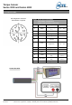
Commissioning
After sensor installation pay attention to the followings:
•Switch on the power supply unit and check the supply voltage. Peak voltage to the sensor must be
avoided! Be sure to verify the power supply voltage before connecting the sensor!
•Connect the sensor to the power supply unit by using the delivered cable.
•Connect the sensor output to a high-resistance device such as an A/D converter, oscilloscope, PC
measurement board. The sensor should be in mechanical unloaded state while connecting it.
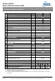
Tare function and error indication:
Series 3000/Series 4000 contains a LED button on the housing surface. Pressing the button will set the
signal output to 5 V. The illumination of the button serves as a function / malfunction indicator.
Functional indicator:
LED off: missing power supply or sensor is damaged
LED on: Sensor is ready.
Error indicator:
LED flashes: The sensor is not ready.
Flashing of LED can have several possible causes. Various causes are interpreted through a flash code.
After each flash code the LED makes a short pause before repeating the code.
2x flashing: Magnet field sensors defective.
4x flashing: Electronics defective.
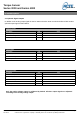
Service / Maintenance
Service-contact:
Tel.: ++49 89 66 56 19 0
Fax: ++49 89 66 56 19 29
Maintenance:
The sensor is free of maintenance, NCTE advises a yearly recalibration. The ball bearing is designed for
a lifetime of 5000 h.
Disposal
For purposes of disposal please send the device back to NCTE AG.
Handling and Transport
While handling, storing and transporting keep sensor away from magnetic and electromagnetic fields
which may exceed the allowed maximum range of EMC listed in Chapter 3. Technical Characteristics of
the Sensor.
Precautions
• Do not open the sensor under any circumstances.
• Do not remove or loosen the locking rings on the shaft ends.
• The mounting nut of the socket as well as the fixing screws should not be loosened or tightened.
• Use only a separate power supply for the sensor
• Use the sensor only according to the specification (Chapter 3. Technical Characteristics of the Sensor).
• Keep the sensor away from magnetic and electromagnetic fields which may exceed the allowed
maximum range of EMC (Chapter 3. Technical Characteristics of the Sensor)
• The sensor is not designed as a step bearing. The existing fixing possibilities serve exclusively for
preventing the sensor from distortion.