
Datasheet


www.ncte.de
Revision L
Nov 2014
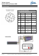
Torque Sensor
Series 3000 and Series 4000
Modifications reserved. All details describe our products in general form only. They are not to be
understood as a guarantee of quality or durability and do not constitute any liability whatsoever.
Page 9
Field of Application
The torque sensor is intended for the use in industrial applications. (e.g. test bench).
Scope of Delivery
The torque sensor set consists of the sensor itself (signal pick-up and signal processing integrated into sensor
housing), one connecting cable with a soldered plug, key stones and the instruction manual.
Installation and Removal
Make sure to install the sensor shafts exactly with the proper aligned connecting shafts. The key stone adapter
/ square endings of the connecting shafts are to be attached forceless to the corresponding ones of the sensor.
The sensor is not designed as a step bearing. No external axial or radial force should be on the housing of the
sensor by fixing it. In case that the bending or radial forces could not avoided the ball bearing of the sensor
must be double-checked. The allowed bearing forces are listed in (Chapter 6. Dimensions). The M4-screw
threads on the side are only for fixing the sensor housing and keeping it from distortion. A maximum cable
length of 5 m must not be exceeded. Using a cable or connector other than supplied by NCTE, or a similar
cable that is of a different length may affect the overall performance of the sensor.
DO NOT REMOVE THE SHAFT WITH TORQUE APPLIED TO THE SENSOR.
Offset Adjustment
If required the zero point output signal (5 V) can be adjusted by pressing the Tare-button. By factory default the
sensor is set to 5 V at Null torque.
Interface Description
Mechanical connection:
The key stone adapters on both ends of the measurement shaft are intended for torque transmission.
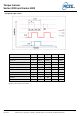
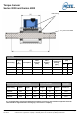
Electrical connector:
On the sensor housing there is a 12-pin socket for the power supply and the signal output.(see Chapter 7.
Connection Plan).
Operation (in regular case or in optimal case)
Optimal measurement parameters may be achieved when the sensor is applied in accordance to the
specification. Use the sensor only for short periods of time at the maximum rotational speed. By compliance
with the specification the sensor works generally trouble-free and maintenance-free.
Irregular Operation, Measures against Disturbance
The presence of external electromagnetic or magnetic fields can lead to irregular measurement results. The
mechanical overload on the sensor (e.g. exceeding of maximum allowed torque or severe vibrations) may
cause damage to the sensor and in consequence the incorrect signal output. In such cases the sensor must be
reset (see Point 8.4 Offset Adjustment). If this does not help, do not open the sensor but contact NCTE AG
directly for assistance.
7. Operating Instructions