High Rate 11Mbps Wireless Networking Access Point User’s Guide Rev.10 DEC 2000 National Datacomm Corporation. 4F, No. 24-2, Industry East 4th Road, Science Park, Hsin-Chu, Taiwan, R.O.C. Tel: 886-3-5783966 Fax: 886-3-5777989 Technical Support E-mail: techsupt@ndc.com.tw NDC World Wide Web www.ndc.com.
TRADEMARKS NDC and InstantWave are trademarks of National Datacomm Corporation. All other names mentioned in this document are trademarks/registered trademarks of their respective owners. NDC provides this document “as is”, without warranty of any kind, neither expressed nor implied, including, but not limited to, the particular purpose. NDC may make improvements and/or changes in this manual or in the product(s) and/or the program(s) described in this manual at any time.
Table Of Contents Introduction........................................................................................................................................ 1 INSTANTWAVE HIGH RATE FAMILY ..........................................................1 SYSTEM REQUIREMENTS ..............................................................................1 CABLING ............................................................................................................1 Glossary............................
Upgrade AP Firmware ....................................................................................18 Reset AP Configuration ..................................................................................18 Trouble Shooting .............................................................................................................................19 Operational Problems...................................................................................19 Technical Support ............................
List of Figures FIGURE 1. SIMPLE WIRELESS INFRASTRUCTURE NETWORK .................... 4 FIGURE 2. AP TO WIRED ETHERNET BRIDGE .......................................... 5 FIGURE 3. MULTIPLE AP NETWORK ....................................................... 5 FIGURE 4. ACCESS POINT ........................................................................ 9 FIGURE 5. ACCESS POINT ........................................................................ 9 FIGURE 6. ACCESS POINT LEDS..............................
Packing List The package should contain the following items: • One Access Point • One diskette for AP Management Software • One AC Power Adapter • This User’s Guide vi InstantWave High Rate Access Point
Introduction Congratulations on choosing one of NDC’s InstantWave High Rate wireless networking product’s family. InstantWave High Rate was one of the first IEEE 802.11b wireless standard compliant products in the industry and was designed to maximize the convenience of networking. You will find InstantWave High Rate products very easy to setup and use. The User’s Guide gives comprehensive instructions on installing and using the InstantWave High Rate Access Point (AP).
Glossary Group ID/BSSID A Group ID (the 802.11 standard uses the term BSSID) is the ID of a wireless cell. A wireless cell is usually made up of stations in an area that the radio signal can comfortably cover. In other words, any wireless station in the cell can communicate with any other within reach of the radio signal. Domain Name/ESSID A “Domain” is most commonly used to refer to a group of computers whose hostnames share a common suffix.
How to Use this Guide InstantWave High Rate is extremely versatile in providing varying levels of network management. For Small Office/Home Office users, setup and configuration is a quick, four-step process. The Access Point Hardware Installation section, on page 9, provides simple instructions to get your network up and running within minutes.
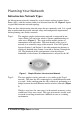
Planning Your Network Infrastructure Network Types An Infrastructure network is formed by several stations and one or more Access Points (APs), with the stations within a set distance from the AP. Figure 1 depicts a typical Infrastructure network topology. There are three infrastructure network setups that are commonly used. It is a good idea to understand the possible network setups and configuration requirements before planning your wireless network. Type 1.
Server Figure 2. AP to Wired Ethernet Bridge Type 3. The third type of network is composed of multiple APs and multiple Stations (Figure 3). The APs could also be connected to servers on the wired Ethernet network. The shadowed area represents signal overlap between subnet1 (AP-1) and subnet2 (AP-3). Figure 3. Multiple AP Network The reasons for having multiple APs installed are: 1. 2.
Planning an Infrastructure Network This section explains some of the things you need to consider in planning an Infrastructure network. Setting up is a two step process. 1. 2. Install and configure the InstantWave High Rate products Decide the best physical location of the InstantWave High Rate products so as to optimize performance The following sections give quick guidelines for these two steps.
Roaming InstantWave High Rate products are equipped with seamless roaming capabilities. Roaming is necessary to prevent mobile Stations from being disconnected from the network as they move around. InstantWave High Rate is designed to allow wireless Stations to roam freely within an infrastructure domain composed of multiple APs with overlapping signal coverage (as in the Type-3 network configuration described in the previous section).
Access Point Placement Guidelines A characteristic of radio communication is the “interference” problem. Radio is receptive to interference. Therefore, the more interference you can avoid, the better performance you will get from wireless products. The following section describes how the InstantWave High Rate AP should be placed to reduce possible interference. A few tips to mention that are particularly significant in a radio wave communications system: 1.
Getting Started Access Point Hardware Installation Access Point Hardware Setup explains how to quickly setup the Access Point for use via a wired Ethernet connection, and using the factory default settings. For installation in networks using other than the default settings, i.e. into existing networks, complete the Hardware Setup and refer to AP COMFig Tool, page 12. To setup a wireless station, refer to the PCI/PC Card User’s Guide. Figure 4. Access Point step1.
Figure 5. Access Point LEDs General Color Red Function Unlit: Power OFF Blinking: Diagnostic test On: Healthy condition On: Abnormal Condition PWR (Power/Status) Green E/N(Ethernet) Color Function Link Green TX/RX Orange Indicates an Ethernet link. If the radio fails, this LED will not light Blinks to indicate Ethernet transmission/reception activity RF Color Function Link Green TX/RX Orange Indicates a wireless link.
step4. From the Choose Destination Location dialog box accept the program files default location, C:\Program Files\Wireless LAN AP SB, or click Browse to choose another location. Then click Next step5. To install the full program, choose Typical. Choosing Custom to open another screen with the option to install only selected parts of the management program. Click Next step6. The setup program will copy the necessary files into the specified directory.
AP COMFig Tool The AP COMFig Tool is a Windows 95/98/ME/NT/2000 based utility that is used via a COM port connection between the AP and a PC. It provides the following functions: • Sets necessary AP parameters (e.g., IP address, Domain name, etc.) • Diagnoses the AP hardware and shows the diagnostic results • Upgrades the AP firmware • Resets the AP Configuration • Manages the APMS Host table Click Start/Programs/Wireless LAN AP SB/AP COMFig Tool to start the program.
AP COMFig Service After connecting with the AP, click on the Service tab to open the Service screen (Figure 7). The Service screen provides access to the management features. Figure 7. AP COMFig Tool/Service Click the View and Modify AP Configuration button. The Configuration screen will open (Figure 8). General The General card (Figure 8) is the first card on the Configuration Screen. Figure 8.
Here you may: AP Alias Name Assign the AP a unique name Domain Name (ESSID) This is more commonly called the Domain Name but is defined in the 802.11 Wireless Standard as ESSID. Stations and AP(s) in the same group must use the same Domain Name The transmission rate at which the data packets are transmitted by the AP. Click Down selector arrows, found to the right of Transmit Rate to select which rate you want to use This value determines the basic rates used and reported for this BSS by the AP.
Channels supported on each carrier set: Channel Center FCC/ Number Frequency Canada (MHz) ETSI Spain France Japan 1 2412 O O O 2 2417 O O O 3 2422 O O O 4 2427 O O O 5 2432 O O O 6 2437 O O O 7 2442 O O O 8 2447 O O O 9 2452 O O O 10 2457 O O O O O 11 2462 O O O O O 12 2467 O O O 13 2472 O O O 14 2484 O Important: In a multiple cell network topology, overlapping and/or adjacent cells using different channels can operate simultaneou
Figure 9. Encryption Click the arrow to the right of the Method field. The pull-down method lists four options: Disabled (default) The station communicates with this Access Point without any data encryption. 40 bit WEP Allows station to communicate with this Access Point through 40 bit WEP key data encryption. 128 bit WEP Allows station to communicate with this Access Point through 128 bit WEP key data encryption.
The first is by entering any text in the Passphrase field. Click the Generate button. It will generate four keys, Key 1, Key 2, Key 3 and Key 4. Select a key number from the dropdown list of the Default Key box. If you do not select a key, key 1 is selected, as it is the default key. Click Apply. Another key generation method is to insert key values directly into the key fields using a keyboard. Select the Key number in the Default Key box.
• Internet Multicast Frames After selecting a protocol for filtering, click the Apply button to make the changes effective immediately, without closing the dialog box, or click OK to accept the changes and close the box. Perform AP Self Diagnostic Test On the Service card, click Perform AP Self Diagnostic Test. The Hardware Diagnosis screen will open (Figure 11) Figure 11. Hardware Diagnosis Click Start and the tests will commence. As each item is tested a yellow arrow will appear alongside it.
Trouble Shooting Operational Problems The Wireless adapter appears to be functioning. The Activity LED is active. However, no network PC can be found when run in Infrastructure Wireless Network mode • You have only one AP, and the PC is not placed too far from it, but the PC still has difficulties finding the AP 1. Check that the antennas are properly connected to the AP and the station 2. Make sure that the AP is powered on and working 3.
20 InstantWave High Rate Access Point
Technical Support If you are having a problem using an NDC product and cannot resolve it, please note the following information and contact NDC Technical Support: • What you were doing when the error occurred • What error messages you saw • Whether the problem can be reproduced • The serial number of your product • The firmware version number. • A copy of the AP configuration file. NDC Technical Support is available via e-mail at: techsupt@ndc.com.
NDC Limited Warranty Hardware NDC (NDC Communications, Inc.) warrants its products to be free of defects in workmanship and materials, under normal use and service, for a period of 12 months from the date of purchase from NDC or its Authorized Reseller and for the period of time specified in the documentation supplied with each product.
Limited Warranty Service Procedures Any product (1) received in error, (2) in a defective or non-functioning condition, or (3) exhibiting a defect under normal working conditions, can be returned to NDC by following these steps: You must prepare: dated proof of purchase product model number & quantity product serial number precise reason for return your name/address/email address/telephone/fax 1. Inform the distributor or retailer 2. Ship the product back to the distributor/retailer with prepaid freight.
Limitation of Liability All expressed and implied warranties of a product’s merchantability, or of its fitness for a particular purpose, are limited in duration to the applicable period as set forth in this limited warranty, and no warranty will be considered valid after its expiration date. If this product does not function as warranted, your sole remedy shall be repair or replacement as provided for above.
EC DECLARATION OF CONFORMITY For the following equipment: Product Name: : InstantWave Wireless Access Point Model Number: : NWH650 Produced by: Manufacturer Name : NATIONAL DATACOMM CORPORATION Manufacturer : 2F, NO. 28, INDUSTRY EAST 9TH ROAD Address SCIENCE PARK, HSINCHU, TAIWAN, R.O.C. is hereby confirmed to comply with the requirements set out in the Council Directive on the Approximation of the Laws of the Member States relating to R&TTE Directive (99/5/EC).
Index A H Access Control ............21, 28, 31–32 Access Point Ethernet Connection to............. 25 Access Rights. Setting........... 21, 31 Alias name.............................. 15, 34 AP COMFig Password ................. 13 AP COMFig Service .................... 14 AP COMFig Tool......................... 13 AP Information............................. 36 AP Setting .................................... 30 Host Table..................................... 23 B I Information, AP .....................
SNMP................................24, 26, 36 Subnet Mask Assigning.................................. 27 Assigning............................ 18, 30 System Requirements ..................... 1 T TCP/IP address....................... 18, 30 Troubleshooting ........................... 39 U Uninstalling .................................. 12 Upgrade AP Firmware ............ 34–36 Upgrade Firmware ........................ 22 V View ............................................. 36 W Wireless Cell..............