1Mbps Wireless NWH6210 Wireless Workgroup Bridge NWH2610 Wireless Ethernet Client/Pro User’s Guide Rev. A1 April 2002 NWH6210 NWH2610 National Datacomm Corporation 4F, No. 24-2, Industry East 4th Road, Science Park Hsin-Chu, Taiwan, R.O.C. Technical Support E-mail: techsupt@ndc.com.tw NDC World Wide Web www.ndclan.
TRADEMARKS NDC and InstantWave are trademarks of National Datacomm Corporation. All other names mentioned in this document are trademarks/registered trademarks of their respective owners. NDC provides this document “as is”, without warranty of any kind, neither expressed nor implied, including, but not limited to, the particular purpose. NDC may make improvements and/or changes in this manual or in the product(s) and/or the program(s) described in this manual at any time.
Packing List The NWH6210 package should contain the following items: • One NWH6210 InstantWave Wireless Workgroup Bridge • Dual Dipole Antenna • A mounting kit (mounting template, screws, and rawl-plugs) • One CD-ROM (Contains InstantWave Management System, User’s Guide, links to online resources) • One AC to DC power adapter • One straight-through RT-45 UTP cable • One cross-over RT-45 UTP cable The NWH2610 package should contain the following items: • One NWH2610 InstantWave Wireless Ethern
Table of Contents INTRODUCTION.................................................................................................. 7 INSTANTWAVE WIRELESS LAN PRODUCTS.............................................. 8 AUTOMATIC DISCOVERY OF INSTANTWAVE PRODUCTS ..................................... 10 SYSTEM REQUIREMENTS FOR THE INSTANTWAVE MANAGEMENT SYSTEM ........ 12 TERMINOLOGY USED IN THIS GUIDE ................................................................... 13 HOW TO USE THIS GUIDE.....................
Wireless Statistics........................................................................................... 45 UPGRADE FIRMWARE .................................................................................... 47 RESET ................................................................................................................. 48 LOAD DEFAULT................................................................................................... 48 ADVANCED SETTING ......................................
List of Figures FIGURE 1. FIGURE 2. FIGURE 3. FIGURE 4. FIGURE 5. FIGURE 6. FIGURE 7. FIGURE 8. FIGURE 9. FIGURE 10. FIGURE 11. FIGURE 12. FIGURE 13. FIGURE 14. FIGURE 15. FIGURE 16. FIGURE 17. FIGURE 18. FIGURE 19. FIGURE 20. FIGURE 21. FIGURE 22. FIGURE 23. FIGURE 25. FIGURE 26. FIGURE 27. FIGURE 28. FIGURE 29. FIGURE 30. FIGURE 31. FIGURE 32. FIGURE 33. FIGURE 36. FIGURE 37. FIGURE 38. SIMPLE WIRELESS INFRASTRUCTURE NETWORK ............................... 17 SINGLE AP NETWORK ...........................
Introduction Congratulations on choosing an InstantWave 11Mbps wireless product. This guide gives comprehensive instructions on installing and using the InstantWave 11Mbps NWH6210 Wireless Workgroup Bridge, the 11Mbps NWH2610 Wireless Ethernet Client/Pro, and also explains how to install and use the IWMS (InstantWave Management System) program.
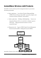
InstantWave Wireless LAN Products InstantWave wireless products provide an integrated solution to your wireless networking requirements. • Indoor applications: Access Point, Wireless Workgroup Bridge (WWB), Wireless Ethernet Client (WEC), and wireless adapters with various bus interfaces (PCMCIA, USB, and PCI) • Outdoor applications: Building-to-Building Bridge. Connects two independent Ethernet LANs via a radio link to eliminate expensive cable laying.
• InstantWave Access Point (AP): This product provides a transparent bridged connection between a wired network and a wireless network and allows Wi-Fi compliant wireless stations to communicate with devices attached to a wired network. Not only does it support wireless stations with wireless LAN adapters, such as PC cards, PCI adapters, and USB adapters, but it also operates together with the NWH6210 Wireless Ethernet Bridge.
Individual or batch mode remote management of the devices, including Multi-Monitor, Batch-Upgrade, Batch-Reset, and Bathc-LoadDefault. Batch mode operation is useful when deploying multiple InstantWave products Friendly user interface with a consistent look and feel Automatic Discovery of InstantWave Products A powerful automatic-discovery algorithm is built into the InstantWave Network Management System.
Windows 95/98 Click Start/Run, type winipcfg, and click OK step1. The IP Configuration dialog box will open step2. Select the network adapter you use to connect to the AP, WWB, or WEC. step3. Click Release Click Renew to retrieve a new IP address, subnet mask, and default gateway address from the AP, WWB, or WEC. Click OK to save the changes and exit the program Windows NT 4.0 step1. Click Start/Programs/Command Prompt. Type “ipconfig /release” and press Enter step2.
System Requirements for the InstantWave Management System System requirements to install and operate the InstantWave Management System are: • An Ethernet drop (UTP) (used to connect to an Ethernet network) • A PC running Windows 95/98/Me/NT4.0/2000/XP • Microsoft Internet Explorer 4.01 or later is required • OS Requirements: 1. On a Windows 95 computer, Microsoft DCOM95 must be installed. You may obtain DCOM95 for Windows 95 from the following Microsoft web location: http://www.microsoft.
Terminology Used in this Guide BSSID/MAC ID BSSID (Basic Service Set ID) is an ID unique to each InstantWave product. It is factory set and is identical to the MAC ID (Media Access Control ID). It allows each InstantWave product to be identified on the network. Domain Name/SSID A “Domain” is most commonly used to refer to a group of computers whose hostnames share a common suffix.
WEP WEP stands for Wired Equivalent Privacy. It is an encryption scheme that provides secure wireless data communication. WEP uses a 40-bit or 128-bit key to encrypt data. In order to decode the data transmission, each wireless client on the network must use identical keys.
How to Use this Guide The User’s Guide gives complete instructions for installation and use of the InstantWave Access Point (AP), Wireless Workgroup Bridge (WWB) and Wireless Ethernet Client (WEC). All of them share a common user interface. The major difference among them is: • The AP has MAC address access control of the wireless stations • The WWB‘s supports up to 16 Ethernet devices. An access table is provided by the WWB to allow 16 Ethernet devices’ MAC addresses to be registered.
Read through the next section ‘Plan the Network’, in order to get the best possible performance from the InstantWave wireless network. Step 1: Step 2: Plan the wireless network Pre-configure the AP, WWB, or WEC before installing it into an existing Ethernet network Refer to Plan the Network, page 17, for details Refer to Hardware Pre-Configuration, page 27, for details.
Plan the Network Infrastructure Network Types An infrastructure network is formed by several stations (WWBs or WECs) and one or more Access Points (APs), with the stations (WWB or WEC) within a set distance from the AP. Figure 1 depicts a typical infrastructure network topology. There are three infrastructure network setups that are commonly used. It is a good idea to understand the possible network setups and configuration requirements before planning your wireless network. Type 1.
network. This time the AP is connected to a wired Ethernet network as a node. In this configuration the AP operates as a bridge between the wired Ethernet network and the wireless networks (Figure 2). Wireless users have the same access to the network resources as they would have if they were wired. This type of network is usually used to extend an existing network into a difficult to wire or a roaming environment. Wired Computers Server Access Point Wireless Computers with WEC Figure 2. Type 3.
Server Wireless Cell A AP-1 Wireless Cell B AP-2 Station -1 Figure 3. Wireless Cell C AP-3 Station -2 Station -3 Multiple AP Network The reasons for having multiple APs installed are: 1. To increase bandwidth in order to boost overall network performance 2. To extend the coverage range Any other type of configuration is usually a mix of these commonly used types.
Ethernet-ready Device with WEC Printer with WEC Figure 4.
Planning an Infrastructure Network This section explains some of the things you need to consider in planning an Infrastructure network. Setting up is a two-step process. 1. Install and configure the InstantWave products 2. Decide the best physical location of the InstantWave products so as to optimize performance The following section gives quick guidelines for these two steps. First, decide whether to have a single AP wireless network or a multiple AP network.
Roaming InstantWave allows wireless stations to roam freely within an infrastructure domain composed of multiple APs with overlapping signal coverage (as in the Type-3 network configuration described in the previous section). For example, roaming enables Station-1 to move from the AP-1 signal coverage area to the AP-2 signal coverage area without disconnecting from the network. The handover is achieved transparently; the Station-1 user would not realize he had moved from AP-1 to AP-2.
In other words, if your network consists of two subnets connected by a router, a mobile station may roam to a different subnet with the same domain name and then fail to communicate with other network devices via TCP/IP. To avoid running into such an awkward situation, you must assign different domain names to different TCP/IP subnets.
Hardware Description NWH6210 Panels and Connectors Figure 5. NWH6210 Front Panel LED Indicators – NWH6210 The Access Point LEDs show the status of the connections. Figure 6.
Power DC-In Port Reset Ethernet Port Figure 7. Antenna Connector NWH6210 Rear Panel Connectors Connector DC Input Ethernet Rest Button Antenna Connector Function DC 5V input Standard RJ-45 Ethernet connector Resets the device if pressed for 1 second. Reboots and loads the factory default settings after a long press (over 5 seconds).
NWH2610 Panels Power Activity Figure 8. NWH2610 Front Panel Reset Ethernet DC-in Port Figure 9.
Hardware Pre-Configuration Before adding a Wireless Workgroup Bridge (WWB) or Wireless Ethernet Client (WEC) into an existing Ethernet network, you may need to set basic configurations, e.g. domain name (SSID), security setting (WEP), WWB (or WEC) name, channel number, or IP address in order to make it compatible with the existing network. Follow the steps below to connect the WWB (or WEC) to a PC for configuration: step1.
Using the InstantWave Management System Once the WWB (or WEC) is connected to an Ethernet network, a network administrator can connect to it from any PC on the same network via the InstantWave Management System (IWMS) utility. The IWMS utility is a Windows-based SNMP management tool, allowing network administrators to remotely configure and monitor the WWB (or WEC) through both an Ethernet and a wireless connection. To launch the IWMS utility: step1.
Auto-Discovery A powerful service discovery protocol has already been built into IWMS utility program. This Discovery Protocol can easily discover all the WWBs (or WECs) connected to the Ethernet back bone within the same subnet. Click the “Discover” Binoculars icon. All InstantWave’s operating devices will be automatically discovered and shown on the Hosts View screen (Figure 13). Figure 12. Auto-Discovery Select one of the wireless devices in the table.
Figure 13. Popup Menu The Status bar at the bottom of the screen shows the number of connecting wireless devices. When the bar shows Ready, Associated will appear on the bar along with the IP address of the associated WWB (or WEC).
Configuration step1. Select the device on the Hosts View screen (Figure 13) step2. Right-click the device to open the popup menu step3. Click Config to go to the configuration pages (Figure 14) Figure 14. DHCP Configuration IP IP Address Setting: A DHCP Client is built into InstantWave WWB and WEC. They will automatically ask the DHCP Server to assign them an IP address. An administrator can assign a fixed IP to a WWB or WEC by un-checking the Obtain IP from DHCP box (Figure 14).
If you assign a fixed IP address to an NWH6110, make sure that all WWBs (or WECs) within the same network have the same TCP/IP subnet address. Obtain IP from DHCP IP Address Subnet Mask Default Gateway Automatically retrieves an IP address to the WWB (or WEC) from a Dynamic Host Configuration Protocol (DHCP) server.
Figure 15. Static IP Configuration After making any changes, click OK to accept the changes and close the box. Filter The next tab on the dialog box is Filter (Figure 16). This is a one-way protocol filtering mechanism that prevents the WWB or WEC from transmitting specified protocols from a wired Ethernet LAN into the wireless LAN. If you do not require particular protocols on the wireless part of your network, you can save bandwidth by enabling the protocol filter.
Figure 16. Configuration/Filter From the Filter card, some, all, or none of the protocols listed may be selected for filtering out: • IP Protocol • IPX Protocol • NetBEUI Protocol • AppleTalk Protocol • Other Protocols • Internet Multicast Frames After selecting a protocol to be filtered, click the OK button.
Wireless Setting To establish radio communication, the following parameters should be properly set. Figure 17.
Name Assigns a unique human-friendly name that allows the WWB or WEC to be easily identified. SSID (Domain Name) This is commonly called the Domain Name and is defined in the IEEE 802.11b Wireless Standard as SSID. Stations, WWBs, WECs, and APs in the same group must use the same Domain Name. Authentication Mode From the dropdown list select: Open system, Shared key, or Both.
Ethernet The WWB can support up to 16 Ethernet PCs. • Ethernet Access Control: Only an Ethernet device whose MAC address is pre-registered on this list is allowed to connect to a WWB (or WEC). Figure 18. Ethernet/Fixed Address 1. Auto Detect: The WWB will automatically sense Ethernet devices connected to it. The maximum number of Ethernet devices is 16. The WEC supports only one Ethernet device. 2.
Idle Time A WWB (or WEC) can expire an Ethernet client when there is no traffic from the client within a set period. Specify an aging time to expire an idle client, or disable this function by checking “Always Connect”. Figure 19. Click OK.
Encryption Data encryption provides secure wireless data communications. Click the Encryption tab to setup/change the security settings (Figure 20). The default is Disabled and initially the keys section will be blank. Figure 20. Configuration/Encryption The pull-down Method box lists three options: 1. Disabled (default) - Disable data encryption 2. 40-bit WEP - Enable use of 40-bit WEP 3. 128-bit WEP - Enable use of 128-bit WEP Key Generation - There are two ways to generate a security key.
button. For 40-bit WEP, it will generate four keys, Key 1, Key 2, Key 3, and Key 4. Select a key number from the dropdown list of the Default Key box. If you do not manually select a key, key 1 will be selected. For 128-bit WEP, only one key will be generated. Click OK. Another WEP key generation method is to insert the key values directly from the keyboard. Enter your own key into one of the Key 1~4 fields. Select that field number in the Default Key field.
SNMP Access Control SNMP Access Control is the next tab on the box (Figure 21). Figure 21. Configuration/SNMP Access Control The WWB (or WEC) contains an SNMP access table to limit access to its configurations. The first time this box is opened, the table will be empty. This means that there are no restrictions on who can access and reconfigure the WWB (or WEC). To avoid chaos on the network, access to the WWB (or WEC) configuration should be restricted to only those for whom it is necessary.
Figure 22. New/Edit Address Two levels of access may be assigned. Read Read-only rights. The user may read everything except the Access Control settings, but cannot alter anything Read/Write The user may read and alter all settings Enter your IP address and then set your own access rights to Read/Write (see the following note). Note: Do not set all the stations in the Access Control table to Read. Once this is set and enabled, it will be impossible to modify the AP settings via IWMS.
When all the settings are made, click OK to return to the SNMP Access Control card. Trap Server Trap Management allows you to setup the configuration of the Trap Server program. When a WWB (or WEC) is powered on, or its Ethernet port becomes active, the WWB (or WEC) will send messages to the assigned trap server to report these activities. To assign a trap server, click New/Edit Trap Server (Figure 23). Assign a station as a trap server by entering its IP address and network port type. Click OK.
or WEC, and the activity. You may save, open, and delete log files from the File menu. To view trap log information, click the icon (telephone set at the upper left corner on main user interface). Important: When all configurations have been completed, click Ok. A dialog box will remind you that a Reset will be required to make the changes effective. Figure 24.
Figure 25. Monitor/Summary Wireless Statistics Click Wireless State for current status (Figure 26). Figure 26.
These statistics will be lost when the WWB (or WEC) reboots or is reset. To refresh the statistics, click on the button to continually refresh information. Click on the button to stop update information Figure 27. Monitor/Statistics The Clients window lists all the currently connected Ethernet devices. Figure 28.
Upgrade Firmware Upgrade Firmware The WWB’s or WEC’s embedded software (firmware) is burned into the flash ROM. However, an updated firmware can be installed over your LAN via the IWMS program. Click on Upgrade Firmware. The Upgrade Firmware dialog box will open (Figure 29). Use the Browse button to choose the file to be uploaded to the WWB or WEC, or type the file name and path in the Select File field. Figure 29. Upgrade Firmware The Upgrade button will then become enabled.
Reset Resetting the WWB or WEC will take about 30 seconds. During this time, the IWMS program will not be able to query the WWB or WEC via the SNMP protocol and the WWB or WEC will not be available to other stations. If you try to access it, the IWMS program will display a “No response from the WEB or WEC” message. Figure 30. Reset the WWB or WEC Configuration Load Default Clicking Load Default opens a dialog box. Click Yes to return the WWB or WEC to the default settings.
Advanced Setting Batch mode operation In order to maximize the efficiency of wireless LAN management, the user can apply batch mode operation to manage the selected WWBs or WECs. You can sort InstantWave devices by the device type first. Then select the multiple WWBs or WECs you would like to manage. Click the right mouse button to open the popup menu. Then choose the tool you would like to work on these specific WWBs or WECs with. Figure 32.
InstantWave Products NWH660 Device Alias Name AP AP1-A-1F Host Table name A-1F NWH7610 AP AP2-A-1F A-1F NWH6210 WWB Room111 A-1F NWH6210 WWB Room112 A-1F NWH7610 AP AP1-B-1F B-1F NWH7610 AP AP2-B-1F B-1F NWH6210 WWB Room111 B-1F NWH6210 WWB Room121 B-1F Explanation AP located at building A and first floor AP located at building A and first floor AP located at building A and first floor AP located at building A and first floor AP located at building B and first floor AP loca
the Host Table to a file (for convenience you could save the Host table on a network disk for ease of access). Import Host Table to check device’s availability Import the Host Table from a file (for convenience you could retrieve the Host table from a network disk for ease of access). Once the Host Table has been imported, the IWMS will automatically check the availability of WWBs or WECs listed on the Host Table.
From here you can also select any WWB or WEC on the table. Edit it or delete it when it is no longer necessary. This table can be saved and retrieved from the IWMS utility so that you don’t need to create it again. Export a Configuration profile to a File The configuration file can be saved to a text file and safely kept. This configuration file can also be imported to recover an InstantWave Product’s lost settings. The profile can also be copied to other InstantWave products of the same kind.
Figure 35. Import the Configuration Profile from a File Encryption The configuration file does not contain the security key settings. The attributes of security keys are externally write-only and cannot be saved into the configuration file. Click Encryption to setup the security keys manually.
Hardware InstantWave Product Placement Guidelines A few tips to mention that are particularly significant in a radio wave communications system: 1. Radio waves reflect or refract from buildings, walls, metal furniture, or other objects. This could result in performance degradation due to the fluctuation of the received signal. 2. Microwave ovens use the 2.45 GHz frequency band. InstantWave also functions in the 2.4 ~ 2.5 GHz band, and therefore shares some of the band with microwave ovens.
step3. Remove the template sheet step4. Tap the rawl-plugs into the drilled holes step5. Screw the supplied screws into the rawl-plugs step6.
Troubleshooting This section provides you with some troubleshooting info should you encounter installation or operation problems on InstantWave products. If the problems still cannot be remedied after going through the Troubleshooting section, check the FAQs at http://www.ndc.com.tw/support/faq.htm If you still have a problem, contact NDC technical support for assistance (see Technical Support, page 58).
The WWB powers up, but the Ethernet Link LED is OFF (no connection to an Ethernet network). Make sure: 1. The Ethernet cable is connected firmly to both the WWB and Hub/Switch. The Status LED on the WWB panel is Red and flashing. Restart (power cycle) the WWB and check the Status LED again. If it is still flashing, you need to return the WWB to the reseller for repair. Transmission performance is slow or erratic. 1. Move your WWB closer to the AP to find a better signal.
Technical Support Support from Your Network Supplier If assistance is required, call your supplier for help. Have the following information ready before you make the call. 1. LED status 2. A list of the product hardware (including revision levels), and a brief description of the network structure 3. Details of recent configuration changes, if applicable Support from NDC If you have any problems that you cannot resolve with the information in troubleshooting, or the FAQs at http://www.ndc.com.
NDC Limited Warranty Hardware NDC warrants its products to be free of defects in workmanship and materials, under normal use and service, for a period of 12 months from the date of purchase from NDC or its Authorized Reseller, and for the period of time specified in the documentation supplied with each product.
Limited Warranty Service Procedures Any product (1) received in error, (2) in a defective or non-functioning condition, or (3) exhibiting a defect under normal working conditions, can be returned to NDC by following these steps: You must prepare: Dated proof of purchase Product model number & quantity Product serial number Precise reason for return Your name/address/email address/telephone/fax 1. Inform the distributor or retailer. 2.
Services after Warranty Period After the warranty period expires, all products can be repaired for a reasonable service charge. The shipping charges to and from the NDC facility will be borne by the purchaser. Return for Credit In the case of a DOA (Dead on Arrival) or a shipping error, a return for credit will automatically be applied to the purchaser’s account, unless otherwise requested.
Specifications General Regulatory Compliance Standards FCC Part 15 Class B. (US) Data Rate 11Mbps/5.5Mbps/2 Mbps/1Mbps auto fallback Communication Method Security Half-Duplex LED Indicators NWH6210: Power, Status, Ethernet, Wireless NWH2610: Status, Wireless Interfaces/Connectors 10Base-T: RJ-45 Wireless LAN: IEEE 802.11b, Wi-Fi Compliant Ethernet: IEEE 802.3 40-bit/128-bit WEP Data Encryption Reverse Type SMA Antenna Connector (NWH6210 only) Power Power Voltage: DC 5.
Transmitter RF Output Power: 20 dBm Frequency Stability: Within ± 25ppm Data Modulation Type: BPSK (1Mbps)/QPSK (2/5.5/11Mbps) Data Modulation Speed: 11Mbps/5.
Appendix This appendix lists the channels supported by the world’s regulatory domains. The channel numbers, channel center frequencies, and regulatory domains are shown in the table.
Index A I Access Control ............................. 41 IP Setting ...................................... 31 Access Rights ............................... 41 L Alias Name................................... 36 APMS Host Table......................... 51 Authentication Mode.................... 36 B Basic Rates ................................... 36 BSSID .......................................... 13 LEDs............................................. 24 Load Factory Configuration.......... 48 M MAC ID.
Regulatory Domains............... 13, 36 Trap Log Information ................... 44 Roaming ................................. 13, 22 Trap Management ......................... 43 S Service Set ID............................... 36 SNMP........................................... 48 Trap Server ................................... 43 U Upgrade AP Firmware (APMS Program) ................................... 47 SNMP Access Control.................. 41 System Requirements ...................