1-Mbps Wireless Access Point User’s Guide Version A1 July 2002 NWH660 National Datacomm Corporation 4th Fl., No. 24-2, Industry East Road IV Science-based Industrial Park Hsinchu, Taiwan, R.O.C. Technical Support E-mail: techsupt@ndc.com.tw NDC World Wide Web www.ndclan.
TRADEMARKS NDC and InstantWave are trademarks of National Datacomm Corporation. All other names mentioned in this document are trademarks/registered trademarks of their respective owners. NDC provides this document “as is,” without warranty of any kind, neither expressed nor implied, including, but not limited to, the particular purpose. NDC may make improvements and/or changes in this manual or in the product(s) and/or the program(s) described in this manual at any time.
Packing List Your NWH660 package should contain the following items: • One InstantWave NWH660 11-Mbps Wireless Access Point (AP) • One mounting kit (mounting template, screws, and screw anchors) • InstantWave Management System (IWMS) and AP COMFig software and user manuals, and this user’s guide, in electronic form (one CD-ROM or four floppy disks) • One RS-232C serial cable InstantWave 11-Mbps Wireless Access Point
Contents INTRODUCTION .................................................................................................. 8 INSTANTWAVE WIRELESS LAN PRODUCTS.............................................. 9 IWMS — THE INSTANTWAVE MANAGEMENT SYSTEM ..................................... 10 AUTOMATIC DISCOVERY OF INSTANTWAVE DEVICES ........................................ 10 IWMS HARDWARE AND SOFTWARE REQUIREMENTS ......................................... 12 TERMINOLOGY USED IN THIS GUIDE ......................
AUTO-DISCOVERY .............................................................................................. 39 CONFIGURATION ................................................................................................. 41 IP .................................................................................................................... 42 Filter............................................................................................................... 43 Wireless ...............................
Figures FIGURE 1. SIMPLE WIRELESS INFRASTRUCTURE NETWORK ................................... 15 FIGURE 2. SINGLE AP NETWORK ........................................................................... 16 FIGURE 3. MULTIPLE-AP NETWORK ...................................................................... 17 FIGURE 4. NWH660 FRONT PANEL........................................................................ 20 FIGURE 5. LED INDICATORS ............................................................................
FIGURE 43. FIGURE 44. FIGURE 45. FIGURE 46. FIGURE 47. FIGURE 48. FIGURE 49. FIGURE 50. UPGRADE FIRMWARE .......................................................................... 57 BATCH MODE OPERATION LIST ........................................................... 58 IMPORT HOST TABLE TO CHECK DEVICE ............................................. 60 NEW/EDIT/DELETE A HOST ADDRESS ................................................. 61 EXPORT THE CONFIGURATION PROFILE TO A FILE .............................
Introduction Congratulations on choosing an InstantWave wireless product. This guide gives comprehensive instructions on installing and using the InstantWave NWH660 11-Mbps Wireless Access Point (AP), and also explains how to install and use the InstantWave Management System (IWMS) software.
InstantWave Wireless LAN Products InstantWave wireless products provide an integrated solution to your wireless networking requirements. • For indoor applications: Access points, wireless workgroup bridges, wireless ethernet clients, and wireless adapters with various bus interfaces (PCMCIA, USB, and PCI). • For outdoor applications: The InstantWave building-to-building bridge connects two independent Ethernet LANs via a radio link, making expensive outdoor cabling unnecessary.
IWMS — The InstantWave Management System IWMS is a powerful network management system that is fully compatible with the industry-standard Simple Network Management Protocol (SNMP). It features: • Automatic discovery of all InstantWave devices that are configured within the same subnet • Individual and batch-mode remote management of InstantWave devices, including Multi-Monitor, Batch-Upgrade, Batch-Reset, and Batch-LoadDefault functions.
stations’ IP settings as described below; otherwise, Windows may continue to use the previous IP address instead of executing the auto-IP procedure. Windows 95/98 step 1. Click Start/Run, type winipcfg, and click OK. The IP Configuration dialog box will open. step 2. Select the network adapter you use to connect to the NWH660. Click Release. step 3. Click Renew to retrieve new information (IP address, subnet mask, and default gateway address) from the DHCP server.
IWMS Hardware and Software Requirements System requirements for installing and operating the InstantWave Management System are: • An x86-based microcomputer running Microsoft Windows 95, 98, Me, NT 4.0, 2000, or XP • Microsoft Internet Explorer 4.01 or later • A connection to an Ethernet network Particular versions of Windows have the following additional requirements: 1. On Windows 95, Microsoft DCOM95 must be installed. You can obtain DCOM95 from the following Microsoft Web page: http://www.microsoft.
Terminology Used in this Guide BSSID/MAC ID The BSSID (Basic Service Set ID) is a factory-set ID unique to each InstantWave WLAN product. It is identical to the MAC ID (Media Access Control ID). It allows each InstantWave product to be identified on the wireless network. ESSID An Extended Service Set ID (often referred to as Service Set ID, or SSID) identifies the wireless LAN domain that an AP is in. A domain is generally composed of wireless APs you are most likely to communicate with.
How to Use this Guide This user’s guide gives complete instructions for installation and use of the InstantWave NWH660 11-Mbps Wireless Access Point (AP). Before putting the NWH660 into operation on your LAN, it is important that you adjust the unit’s settings to conform to your networking environment. This can be done with either of two tools included in the NWH660 package: the AP COM-port Configuration utility (AP COMFig) or the InstantWave Management System (IWMS).
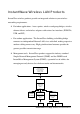
Planning the Network Infrastructure Network Types An infrastructure network is formed by several stations and one or more access points (APs), with the stations within a set distance from the AP or APs. Figure 1 depicts a typical infrastructure network topology. There are three infrastructure network setups that are commonly used. It is a good idea to understand the possible network setups and configuration requirements before planning your wireless network. Type 1.
Type 2. The next simplest wireless network is very similar to the Type 1 network. This time the AP is connected to a wired Ethernet network as a node. In this configuration the AP operates as a bridge between the wired Ethernet network and the wireless networks (Figure 2). Wireless users have the same access to network resources as they would have if they were wired. Such a configuration is often used to allow roaming, or to extend an existing network into a hard-to-wire environment.
Server “Sales” Domain Wireless Cell A Wireless Cell B AP-1 AP-2 Station -1 Wireless Cell C AP-3 Station -2 Station -3 Figure 3. Multiple-AP Network The reasons for having multiple APs installed are: 1. To increase bandwidth in order to boost overall network performance 2. To extend the coverage range Any other configuration is usually a mix of these commonly used types.
Planning an Infrastructure Network This section explains some of the factors you need to consider when planning an infrastructure network. Setting up is a two-step process: 1. Install and configure the InstantWave wireless products. 2. Decide the best physical location of the InstantWave wireless products so as to optimize performance. The following section gives quick guidelines for these two steps. First, decide whether to have a single AP wireless network or a multiple AP network.
Roaming InstantWave products allow wireless stations to roam freely within an infrastructure domain composed of multiple APs with overlapping signal coverage (as in the Type 3 network configuration described in the previous section). For example, roaming enables Station 1 to move from the AP 1 signal coverage area to the AP 2 signal coverage area without disconnecting from the network. The handover is achieved transparently; the Station 1 user would not realize he had moved from AP 1 to AP 2.
Hardware Description Figure 4. NWH660 Front Panel LED Indicators The NWH660’s LEDs show the status of the unit and its connections. Figure 5.
Connectors and Switches Power Switch Power Jack Reset Button Ethernet Port Serial Port Antenna Connector Figure 6. NWH660 Rear Panel Item Function Power jack Power switch Ethernet port DC 5V power input Device on/off RJ-45 jack for connection to 10Base-T Ethernet LAN If held down more than 3 seconds, reloads factory settings and restarts device. Power LED will blink during reset and then go off to indicate that button can be released.
Hardware Pre-configuration Before adding the NWH660 to an existing Ethernet network, you may need to set basic parameters — e.g., SSID, security settings (WEP), AP name, channel number, and IP address — to make the AP compatible with the existing network. From the AP COMFig utility: Follow the steps below to connect the AP to a PC for configuration: step 1. Connect the supplied RS-232 cable to the AP’s serial port and connect the other end to a serial port (COM port) on the PC. step 2. Power up the AP.
Using the AP COMFig Tool The AP COMFig Tool is a Windows-based utility used to configure the AP via a COM port connection between the AP and a PC. It provides the following functions: • Sets AP parameters (e.g., IP address, domain name [SSID], security, etc.) • Diagnoses the AP hardware and shows the results • Upgrades the AP firmware • Resets the AP configuration To start the AP COMFig Tool, click Start/Programs/InstantWave High Rate AP/AP COMFig Tool.
Figure 8. AP COMFig Tool/Password AP COMFig/Service After connecting with the AP, click the Service tab to open the Service panel (Figure 9). The Service panel provides access to AP management features. Figure 9. AP COMFig Tool/Service Click the View and Modify AP Configuration button. The Configuration window will open (Figure 10).
General: The General panel (Figure 10) is the first panel in the Configuration section. Figure 10. Configuration/General On this panel, you can set and view general AP settings. These settings are explained in the table below.
AP Alias Name Assigns the AP a unique human-friendly name that allows the AP to be easily identified. Domain Name (SSID) This is commonly called the domain name but is defined in the IEEE 802.11b wireless standard as SSID. Stations and APs in the same group must use the same domain name. Transmission Rate Sets the transmission rate at which data packets are transmitted by the AP. This value determines the basic rates used and reported for this BSS by the AP.
After making any changes, click the Apply button to make the changes effective immediately, without closing the dialog box, or click OK to accept the changes and close the box. Encryption: Data encryption provides more secure wireless data communications. Click the Encryption tab to create or change the security settings (Figure 11). The default is Disabled and initially the keys section will be blank. Figure 11. Configuration/Encryption The dropdown Method box lists three options: 1.
Key Generation - There are two ways to generate a security key. The first is by entering any text in the Passphrase field. Click the Generate button. For 40-bit WEP, it will generate four keys, Key 1, Key 2, Key 3, and Key 4. Select a key number from the dropdown list of the Default Key box. If you do not manually select a key, key 1 will be selected. For 128-bit WEP, only one key will be generated. Click Apply. Another WEP key generation method is to insert the key values directly from the keyboard.
If you assign a fixed IP address to an NWH660, make sure that all NWH660s within the same network have IP addresses on the same TCP/IP subnet. Obtain IP from DHCP IP Address Subnet Mask Default Gateway Automatically retrieves an IP address for the NWH660 from a Dynamic Host Configuration Protocol (DHCP) server.
a wired Ethernet LAN into the wireless LAN. If you do not require particular protocols on the wireless part of your network, you can save bandwidth by enabling the protocol filter. Figure 13.
SNMP Access Control: SNMP Access Control is the next tab on the box (Figure 14). Figure 14. Configuration/SNMP Access Control The AP’s access control is managed by a control table on the AP. The first time this box is opened, the table will be empty. This means that there are no restrictions on who can access and reconfigure the AP and any user may modify the AP’s operation. To avoid chaos on the network, access to the AP configuration should be restricted to only those for whom it is necessary.
Two levels of access are available: Read Read-only rights. The user may read everything except the Access Control settings, but cannot alter anything Read/Write The user may read and alter all settings Enter your IP address and then set your own access rights to Read/Write (see the following note). Note: Do not set all the stations in the Access Control table to Read-only. Once this is set and enabled, it will be difficult to modify the AP.
Figure 16. Hardware Diagnosis Click Start and the tests will commence. As each item is tested, a yellow arrow will appear alongside it. If the test is successful, the arrow will change to a green check mark. If a failure occurs, an “X” will appear. You can click Cancel at any time to stop the tests. When the tests are finished, the Cancel button will change to a Close button. Click Close to return to the Service panel.
Use the Browse button to choose the file to be uploaded to the AP, or type the file location and name in the File Name field. The Upload button will then become enabled. Click Upload. The new firmware will be loaded into the AP’s flash memory area. When the file transfer is complete, click OK to begin the AP’s internal firmware updating process.
For the best performance, follow the guidelines below in placing the product: • Place as high as possible, in as open an area as possible • Avoid placing the AP (especially the antenna) close to metal objects (e.g. file cabinets, metal cubicles, etc.) • Keep APs and stations as far away as possible from microwave ovens (10 meters min. is advisable) When you have decided on a location, follow the steps below to complete the installation. step 1. Screw the antenna into the back of the AP.
Installing the InstantWave Management System step 1. Insert the InstantWave Management System disk into floppy drive A:. Click Start/Run and type a:\setup.exe. The setup program will prepare the InstallShield Wizard and then display a Welcome window. Figure 19. Welcome step 2. Click Next.
Figure 20. Important Issues step 3. Older operating systems may need to update some system files to function correctly with the InstantWave Management System. If required, follow the on-screen instructions to download the required file (Figure 20). Click Next to open the Choose Destination Location window (Figure 21). Figure 21. Choose Destination Location step 4. Click Next.
Figure 22. Select Program Folder step 5. Click Next again (Figure 22). Figure 23. Setup Complete step 6. Check “I would like to launch InstantWave Management System” and click Finish.
Using the InstantWave Management System Once the NWH660 is connected to an Ethernet network, a network administrator can connect to it from any PC on the same network via the InstantWave Management System (IWMS) utility. The IWMS utility is a Windows-based SNMP management tool allowing network administrators to remotely configure and monitor the NWH660 through both an Ethernet and a wireless connection. To launch the IWMS utility: step 1.
Figure 24. InstantWave Management System step 2. Select one of the wireless devices on the list. The utility buttons on the left toolbar will be enabled (Figure 25). step 3. Right-clicking on a particular device will open a popup menu offering the same functions as the toolbar.
Figure 25. Popup Menu Configuration step 1. For configuration, select the AP (NWH660) on the Hosts View window (Figure 24) step 2. Right-click the NWH660 to open the popup menu step 3.
Figure 26. IP Configuration IP IP Address Setting: The InstantWave NWH660 is a DHCP client. It will automatically ask the DHCP server to assign it an IP address. An administrator can assign a fixed IP to an NWH660 by unchecking the Obtain IP from DHCP box (Figure 26). You may also configure a subnet mask and add a default gateway. If you assign a fixed IP address to an NWH660, make sure that all NWH660s within the same network have the same TCP/IP subnet address.
another LAN, the SNMP response packet needs to be forwarded by routers. The default gateway is the closest router to the NWH660. If the correct default gateway is set, you can use an IWMS manager (i.e. a PC running IWMS) physically located in a different subnet to manage this NWH660. Filter The next panel in the configuration dialog box is Filter (Figure 27). Figure 27.
• NetBEUI Protocol • AppleTalk Protocol • Other Protocols • Internet Multicast Frames Wireless The Wireless panel (Figure 28) provides access to the Wireless settings. Figure 28. Configuration/Wireless These settings are explained in the following table. Name SSID Assigns the NWH660 a unique name that allows the AP to be easily identified on the network. Identifies the wireless LAN domain that this AP is in. A domain is generally composed of wireless APs you are most likely to communicate with.
Broadcast SSID Click to enable or disable the SSID broadcasting feature: If disabled, the NWH660 will: • Blocks a connection request from a station without the correct SSID • Hides the SSID in outgoing beacon frames. A site-survey tool will not find the SSID Transmission Rate Sets the transmission rate at which the data packets are transmitted by the NWH660.
MAC Access Control This feature lets you limit access to the network through the access point. You can list up to 1000 stations that are to be granted or denied access. A drop-down box lets you select the method of access control: • Disabled: Disable MAC-address access control. This is the default setting. • Accepted List: Only wireless stations whose MAC addresses are on the list are allowed to connect through the access point.
Figure 29. Configuration/Mac Access Control Wireless stations registered in the MAC Address Control Table can be individually turned on or off. For example, if you have enabled the Accepted List option, you can check the Not Use option for any listed station; the access point will then refuse all connection attempts from that station.
Encryption Click the Encryption tab (Figure 30) to set up the security options. Figure 30. Configuration/Encryption The default setting is Disabled and initially the key sections are blank. The pull-down Method box lists three options: • Disabled (default) - Disable data encryption • 40-bit WEP - Enable use of 40-bit WEP • 128-bit WEP - Enable use of 128-bit WEP Key Generation - There are two ways to generate a security key. The first is by entering any text in the Passphrase field.
Another WEP key generation method is to insert the key values directly from the keyboard. Enter your own key into one of the Key 1~4 fields. Select that field number in the Default Key field. SNMP Access Control The AP contains an SNMP access table to limit access to its configurations. By default there is no restriction on accessing the AP. To avoid chaos on the network, access to the NWH660 configuration should be restricted to only those who require access.
Figure 32. New/Edit Address Two levels of access may be assigned: Read Read/Write Read-only rights. The user may read everything except the Access Control settings, but is not allowed to alter anything The user may read and alter all settings Enter your PC’s IP address and then set your own access rights to Read/Write (see the following note). Note: Do not set all the stations in the Access Control table to Read only. Once this is set and enabled, it will be impossible to modify the NWH660.
the event. You can save, open, and delete log files from the File menu. To assign a trap server, click Trap Server (Figure 33). Figure 33. Configuration/Trap Server Assign a station as a trap server by entering its IP address and network port type. Click Edit address. To remove a trap server from the list, highlight it and click Clear address. Click Clear all address to remove all assigned trap servers from the list (Figure 34). Figure 34.
To view trap log information, click the Start Trap View icon (a ringing telephone) in the upper left corner of the main IWMS window (see Figure 24, page 40). A window such as that shown below will appear (Figure 35). Figure 35. Trap View The log shows when an NWH660 was powered on, or an Ethernet port became active, and the IP address of the reporting NWH660. You can save, open, and delete log files through the File menu. Important: Once all configurations have been completed, click OK.
Monitor The Monitor tool allows the NWH660’s status, Ethernet statistics, wireless statistics, and other configuration information to be viewed/monitored. In the Hosts View window (Figure 37), select a device and click the Monitor button on the toolbar or on the popup menu. Figure 37. Monitor An information window will appear. The first of three panels in this window, the Summary panel, will be visible (Figure 38).
Figure 38. Monitor/Summary Summary Information The information shown is read-only.
Figure 39. Monitor/Statistics The Connected Wireless Stations window lists all the currently associated wireless station’s Media Access Control (MAC) addresses. When finished viewing, click X to close the window. Figure 40.
Reset Resetting the NWH660 will take about 30 seconds (Figure 41). Figure 41. Reset the AP Configuration During this period, the IWMS program will not be able to query the NWH660 via the SNMP protocol and the NWH660 will not be available to its client stations. If you try to access the device, the IWMS program will display the message “Timeout! No response from agent . . .” Load Default Click Load Default if you want to return the device to its factory default settings.
Figure 43. Upgrade Firmware Browse for the file to be uploaded to the NWH660, or type the path and file name into the Select File field. The Upgrade button will then become enabled. Click Upgrade to start downloading the file to the NWH660. The IWMS and the NWH660’s built-in Trivial File Transfer Protocol (TFTP) client/server will load the new executable into the NWH660’s flash ROM area. If the download activity fails, an error message will be shown in the message box.
Advanced Settings Batch mode operation In order to maximize the efficiency of wireless LAN management, you can use batch mode operation to manage selected APs or WEBs. You can sort InstantWave devices by device type first. Then select the multiple APs or WEBs you would like to manage. Next, click the right mouse button to open the tool bar; then choose the functional tool you would like to use to work on these specific APs or WEBs. Figure 44.
group with a specific Host Table name so that you can divide the wireless network into many small groups. A wireless LAN in the hotel application will be a typical example.
Import Host Table to check device’s availability Import the Host Table from a file (for convenience, you can retrieve the Host table on a network disk for the ease of access). Once the Host Table is imported, IWMS will automatically check the availability of APs and WEBs listed in the Host Table. This is an extremely powerful feature to make up for the inadequacy of Auto-Discovery. Auto-Discovery can only find InstantWave devices when they are alive. Failed devices cannot be found via Auto-Discovery.
Figure 46. New/Edit/Delete a Host Address From here you can also select any AP or WEB on the table. Edit it for the modification or delete it whenever it is no longer necessary. This table can be saved and retrieved from the IWMS utility so that you don’t need to create such a table again in the IWMS utility. Export the Configuration profile to a File The configuration file can be saved to a text file and safely kept.
Import the Configuration Profile from a File If there is an accident, the configuration file can also be imported to recover the InstantWave product’s original settings. This profile can also be copied to the other InstantWave product of the same kind. To do this, first click the Import button in the Configuration window. Then; enter the file name for the configuration profile to be imported from.
Figure 50. Import the Configuration Profile from a File (3) Encryption The configuration file does not contain the security key settings. The attributes of security keys are externally write-only and cannot be saved into the configuration file. Click Encryption to set up the security keys manually.
FAQs The FAQs section attempts to answer the most commonly asked questions about InstantWave wireless access points. Question Answer At what radio frequency In the U.S., wireless LAN radios transmit and receive does an AP on one of 11 channels in the 2.4-GHz frequency band. communicate? This is a public band, and does not require a license from the FCC.
Troubleshooting This section provides you with some troubleshooting info should you encounter installation or operation problems on InstantWave products. If the problems still cannot be remedied after going through the Troubleshooting section, check the FAQs on page 64 of this manual and at http://www.ndc.com.tw/support/faq.
Transmission performance is slow or erratic. 1. Change the direction of the antenna slightly. 2. There may be interference, possibly caused by a microwave oven, 2.4-GHz wireless phone, or metal objects. Move these interference sources or change the location of the wireless PC or AP. 3. Change the wireless channel on the NWH660. 4. Check that the NWH660 antenna, connectors, and cabling are firmly connected.
Technical Support Support from Your Network Supplier If assistance is required, call your supplier for help. Have the following information ready before you make the call. 1. LED status 2. A list of the product hardware (including revision levels), and a brief description of the network structure 3. Details of recent configuration changes, if applicable Support from NDC If you have any problems that you cannot resolve with the information in troubleshooting, or the FAQs at http://www.ndc.com.
NDC Limited Warranty Hardware NDC warrants its products to be free of defects in workmanship and materials, under normal use and service, for a period of 12 months from the date of purchase from NDC or its Authorized Reseller, and for the period of time specified in the documentation supplied with each product.
Limited Warranty Service Procedures Any product (1) received in error, (2) in a defective or non-functioning condition, or (3) exhibiting a defect under normal working conditions, can be returned to NDC by following these steps: You must prepare: !" Dated proof of purchase !" Product model number and quantity !" Product serial number !" Precise reason for return !" Your name/address/email address/telephone/fax 1. Inform the distributor or retailer. 2.
Services after Warranty Period After the warranty period expires, all products can be repaired for a reasonable service charge. The shipping charges to and from the NDC facility will be borne by the purchaser. Return for Credit In the case of a DOA (Dead on Arrival) or a shipping error, a return for credit will automatically be applied to the purchaser’s account, unless otherwise requested.
Specifications General Regulatory Compliance FCC Part 15 Class B (U.S.) Standards Wireless LAN: IEEE 802.11b, Wi-Fi Compliant Ethernet: IEEE 802.3 Data Rate 11, 5.5, 2, and 1 Mbps, with auto fallback Communication Method Half-duplex Security 40-bit and 128-bit WEP data encryption LED Indicators Power, Status, Ethernet, Wireless Interfaces/Connectors 10Base-T: RJ-45 Reverse-type SMA Antenna Connector Power Input Voltage: 5.
Wireless Specifications Emission Type Radio Frequency Range Direct Sequence Spread Spectrum 2471 to 2497 MHz (Japan) 2400 to 2483.5 MHz (North America, Europe, and Extended Japan Band) 2445 to 2475 MHz (Spain) Transmitter 2446.5 to 2483.5 MHz (France) RF Output Power: 20 dBm Frequency Stability: Within ±25 ppm Data Modulation Type: BPSK (1 Mbps), QPSK (2/5.5/11 Mbps) Receiver Sensitivity Antenna Type Data Modulation Speed: 11/5.
Appendix This appendix lists the channels supported by the world’s regulatory domains. The channel numbers, channel center frequencies, and regulatory domains are shown in the table.
Index Access Control ............................. 31 IP Setting ................................ 28, 42 Access Rights ............................... 31 LEDs............................................. 20 Alias Name................................... 26 Load Default ................................. 56 AP COMFig MAC Access Control.................... 46 Password................................... 23 MAC Address ............................... 55 Service......................................
Service Set ID............................... 26 Trap Log Information ................... 52 Service/AP COMFig .................... 24 Trap Server ................................... 50 SNMP Access Control............ 31, 49 Upgrade AP Firmware (AP COMFig SSID ....................................... 13, 44 Program) ................................... 33 Statistics ....................................... 54 Upgrade Firmware ........................ 56 Subnet Mask.................................