
User's Manual Part 4


INITIAL LINE UP ROI-S05750
3-23
Chart 3-5 (Cont’d)
Step Procedure
WAVEGUIDE CONNECTION TYPE
Azimuth Angle Adjustment (Waveguide Connection Type)
Note: Take care that the flexible waveguide is not forcedly twisted by
rotating the antenna.
When the HS/SD system is configured, alternately switchover
the transmitter to the other channel (No.1 or No.2) at the
opposite station and repeat adjustment of elevation and azimuth
to obtain satisfactory results in both No.1 and No.2 CH. (Refer
to Chart 3-8 for TX SW/RX SW Manual Switchover Operation).
1’ Loosen all strut attachment hardware,
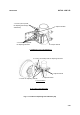
2’ Loosen bolts indicated by arrows in Fig 3-4 (4/4)-A,
3’ Loosen jam nuts and rotate turnbuckle-1 in Fig 3-4 (4/4)-A so
that the RX LEVEL MON voltage obtains the maximum value,
4’ Carefully, tighten turnbuckle-1 jam nuts and bolts indicated by
arrows in Fig 3-4 (4/4)-A to hold the adjustment,
Elevation Angle Adjustment (Waveguide Connection Type)
5’ Make sure that all strut attachment hardware is loosened,
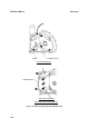
6’ Loosen bolts indicated by arrows in Fig 3-4 (4/4)-B,
7’ Loosen jam nuts and rotate turnbuckle-2 in Fig 3-4 (4/4)-B so
that the RX LEVEL MON voltage obtains the maximum value,
8’ Carefully, tighten turnbuckle-2 jam nuts and bolts indicated by
arrows in Fig 3-4 (4/4)-B,
XPD Adjustment (Waveguide Connection Type)
Note: This XPD adjustment using cross-polarization signal should be
done more carefully than using co-polarization signal because
XPD changes sharply in the axial direction.
9’ At opposite station, turns the ODU of the Sub Master channel
power OFF (for both No.1 and No.2 Sub Master channels in 1+1
system),
10’ In this conditions, check the RX LEVEL MON indication value
for XPD at the ODU of the Sub Master channel,