WARNING TO PREVENT FIRE OR SHOCK HAZARDS, DO NOT EXPOSE THIS UNIT TO RAIN OR MOISTURE. ALSO, DO NOT USE THIS UNIT’S POLARIZED PLUG WITH AN EXTENSION CORD RECEPTACLE OR OTHER OUTLETS UNLESS THE PRONGS CAN BE FULLY INSERTED. REFRAIN FROM OPENING THE CABINET AS THERE ARE HIGH VOLTAGE COMPONENTS INSIDE. REFER SERVICING TO QUALIFIED SERVICE PERSONNEL. CAUTION CAUTION: TO REDUCE THE RISK OF ELECTRIC SHOCK, MAKE SURE POWER CORD IS UNPLUGGED FROM WALL SOCKET.
ENGLISH K This monitor cannot be used in the interlaced mode. K When the Apple Power Macintosh® is used, use the “On The Fly” mode. Please refer to the operation manuals of your computer and video cards for further details. As an E NERGY S TAR ® partner, NEC has determined that this product meets the E NERGY STAR ® guidelines for energy efficiency. NOTES: K For ergonomic reasons, it is recommended not to use blue characters on a dark background.
Federal Communications Commission Requirements This equipment has been tested and found to comply with the limits for Class B digital devices, pursuant to Part 15 of the FCC Rules. These limits are designed to provide reasonable protection against harmful interference in a residential installation. This equipment generates, uses, and can radiate radio frequency energy and, if not installed and used in accordance with the instructions, may cause harmful interference to radio communications.
WARNING • DO NOT OPEN THE MONITOR. There are no user serviceable parts inside and opening or removing covers may expose you to dangerous shock hazards or other risks. Refer all servicing to qualified service personnel. • Do not damage the power cord (ex, placing any heavy objects on the power cord). The damage to the cord may cause shock or fire.
Features High-quality liquid crystal panel • The 15 inch (0.297 mm pixel pitch) panel and anti-glare hard coating enables low reflection, anti-static, high-resolution and high-contrast characteristics and equivalent of 16.19 million colors display (full-color) is also possible. • Bass-reflex type stereo speakers (1 W +1 W) are used for bass reproduction.
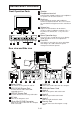
Names and Functions Front Operation Parts 1 Speaker 2 Headphone terminal Commercially available audio stereo headphones or speakers can be connected here. 3 Mute key Turns the built-in speaker and headphone terminal sound ON and OFF. Press once to turn the sound OFF and again to turn the sound back ON. 4 Volume key 1 Adjusts the sound volume for the built-in speakers and the headphone terminals. The “−” key lowers the volume; the “+” key raises the volume.
Connections Always turn off the power supply of the computer and the monitor before performing the connection procedures. The connection method differs depending on the type of computer the monitor is connected to. Refer to the following page to connect the monitor. When other types of computers are used, refer to their operation manual for the correct connection procedures.
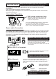
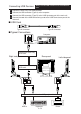
Using the Multi-media Functions Your personal computer must have a voice input / output function. Always use the accessory cable provided. Using the Speakers Prepare the speaker cable (accessory) and connect as shown in the illustration below. Connect the cable to the AUDIO IN terminal on the back panel of the main unit. ■ To an IBM PC or Compatible Connect the speaker cable to the AUDIO OUT terminal of the computer. ■ To a Macintosh Connect the speaker cable to the SPEAKER terminal of the computer.
Connecting USB Devices Always use the USB cord that is enclosed with the unit. 1 Prepare the accessory USB cord provided. 2 Connect the USB connector (Type A) to the computer. 3 Connect the USB connector (Type B) to the USB Upstream port of the main unit. 4 Connect the cord of the USB device being used to the USB Downstream port of the main unit. ■ USB Cord Type A Connector Type B Connector ■ Typical Connections Computer Connect the accessory USB cord.
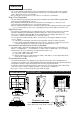
Always use the power supply cord that is enclosed with the unit. AC Power Cord If the enclosed power supply cord is not used, use a power cord that conforms to the following regional standards. U.S.A. .................. UL Switzerland .......... SEV Canada ................ CSA Britain ................... BASEC / BS Germany .............. VDE In other regions, for safety please use an AC plug cord that complies with each country’s safety regulations.
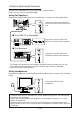
On-Screen Display (OSD) The meaning of the items displayed in the on-screen display are described below. − and + keys Mute and Volume key These keys set the level of the adjustment items. Direct operation: These keys perform the screen display contrast and other adjustments. Adjusts the sound volume for the built-in speakers and the headphone terminals. MENU key v and ukeys This key turns the menu screen on and off.
Operation Procedures Refer to the figures below to perform adjustments in the on-screen display. Auto size adjustment 1. Press the MENU key to display the main menu. 2. Press the menu operation keys (v and u) to shift the “s” mark on the menu screen to the auto size ( ) adjustment. 3. Use the menu operation key (+ key) to select ON. Auto size adjustment will start operating. 4. If the settings on the screen are satisfactory, press the MENU key to record the settings and exit. 5.
Adjustments Menu Screen The menu screen changes to two different screens according to the screen resolution. The menu screen is displayed by the MENU key. The adjustment items of this unit are displayed as icons. Each icon indicates an adjustment item shown in the figure. When the resolution is 640 × 400 to 832 × 624 CONTRAST V. SIZE BACKLIGHT H. POSITION COLOR TEMP VIDEO LEVEL ADJ H. SIZE V. POSITION DISP. FREQ LANGUAGE AUTO SIZE RECALL OSD POSITION PICTURE CONTRAST BACKLIGHT H.
Adjustment Item Screen V. POSITION The vertical position of the image can be adjusted. V. SIZE *Adjustment items when the resolution is set from 640 × 400 to 832 × 624. The vertical size of the image can be adjusted. After aligning the top edge of the image by the vertical position adjustment, change to the vertical size adjustment and perform the adjustment by the “+” or “−” key. However, the optimal adjustment cannot be performed in all operation modes. H.
Adjustment Item Screen AUTO SIZE The following adjustment items are automatically performed for the signal input from the computer. The horizontal position adjustment, horizontal size adjustment, vertical position adjustment, vertical size adjustment, vertical fine adjustment (V. FINETUNE) and horizontal fine adjustment (H. FINETUNE) . Effective adjustment can be performed if this function is used. • Always operate the unit after the computer has started.
Power Management System This monitor conforms to the VESA DPMS standard. This function can suppress power consumption for the display unit. The computer and video board being used must also conform to the VESA DPMS standard. Note: Regarding operation, please consult the Operation Manuals for the hardware being used. Modes change in response to input signals as indicated in the table below.
If Trouble Occurs If problems continue even after the inspections described below are performed, always remove the power plug and contact our dealer. Please observe the following points to ensure safety. Symptom The pilot LED does not light. There is no image. The pilot LED does not go off. Check Remedy Reference Page Power cord / plug Power switch Signal cable Computer (The power saving function might have operated. If this occurred, the pilot LED will be light amber.
If Trouble Occurs Symptom Check Remedy The display color is abnormal. Signal cable The screen size and position do not change. Is the input synchronization Check the video output mode from the signal within the computer and select a mode within the LCD operating range? monitor operating range. (For details, read the operation manual of the hardware you are using.) Are two or more keys Operate only one key at a time. being operated at the same time? The front panel keys fail to operate.
Preset Mode Mode Resolution The 15 timings in the following table have been preset. Horizontal frequency (kHz) Vertical frequency (Hz) Synchronization signal polarity Horizontal Vertical VGA 480 at 60 Hz VGA 400 at 70 Hz 640 × 480 640 × 400 31.47 31.47 59.94 70.08 – – – + 640 × 480 at 72 Hz 640 × 480 37.86 72.81 – – 640 × 480 at 67 Hz 640 × 480 at 75 Hz 640 × 480 640 × 480 35.00 37.50 66.67 75.00 – – – – 800 × 600 at 56 Hz 800 × 600 at 60 Hz 800 × 600 800 × 600 35.16 37.88 56.
TCO’95 Congratulations! You have just purchased a TCO’95 approved and labelled product! Your choice has provided you with a product developed for professional use. Your purchase has also contributed to reducing the burden on the environment and also, to the further development of environmentally adapted electronics products.
Environmental Requirements Brominated flame retardants Brominated flame retardants are present in printed circuit boards, cables, wires, casings and housings. In turn, they delay the spread of fire. Up to thirty percent of the plastic in a computer casing can consist of flame retardant substances.