PlasmaSync Plasma Monitor User’s Manual NEC Solutions (America), Inc.
Introduction Introduction to the PlasmaSync 42VP4, 42VP4D Plasma Monitor NEC’s PlasmaSync™ is a seamless blend of cutting-edge visual technology and sophisticated design. At 42 inches, with a 16:9 aspect ratio, the PlasmaSync™ certainly makes a big impression. However, at a mere 89 mm thin, the monitor’s sleek techno-art lines blend in well with your environment. PlasmaSync’s crisp, vivid image quality will transform data from any graphic medium from PCs to DVD players- into art.
Important Information Precautions Warnings and Safety Precaution Please read this manual carefully before using your plasma monitor and keep the manual handy for future reference. This plasma monitor is designed and manufactured to provide long, trouble-free service. No maintenance other than cleaning is required. Please see the section “Plasma monitor cleaning procedure” on the next page. The plasma display panel consists of fine picture elements (cells) with more than 99.99 percent active cells.
NOTE: When you connect a computer to this monitor, use an RGB cable including the ferrite core on both ends of the cable. And regarding DVI and power cable, attach the supplied ferrite cores. If you do not do this, this monitor will not conform to mandatory FCC standards. Attaching the ferrite cores: Set the ferrite cores on both ends of the DVI cable (not supplied), and both ends of the power cable (supplied). Close the lid tightly until the clamps click.
Recommandations importantes Précautions Veuillez lire avec attention ce manuel avant d’utiliser le moniteur à plasma et le conserver accessible pour s’y référer ultérieurement. ATTENTION RISQUE D’ELECTROCUTION NE PAS OUVRIR MISE EN GARDE: AFIN DE REDUIRE LES RISQUES D’ELECTRO-CUTION, NE PAS DEPOSER LE COUVERCLE, IL N’Y A AUCUNE PIECE UTILISABLE A L’INTERIEUR DE CET APPAREIL. NE CONFIER LES TRAVAUX D’ENTRETIEN QU’A UN PERSONNEL QUALIFIE.
REMARQUE: Pour raccorder un ordinateur à ce moniteur, procéder à l’aide d’un câble RGB à âme de ferrite aux deux extrémités. Sur les câbles DVI et les câbles d’alimentation électrique, fixer les âmes de ferrite fournies aux extrémités. Si vous ne le faîtes, le moniteur ne sera pas en conformité avec les exigences des standards FCC. Fixation des noyaux en ferrite. Monter les tores en ferrite aux deux extrêmités du câble DVI (non fourni) et aux deux extrêmités du câble d’alimentation électrique (fourni).
Contents How to Attach Options to the Plasma Monitor .... 1 Part Names and Function .................................. 2 Front View .............................................................. Rear View / Terminal Board ...................................... Remote Control ........................................................ Battery Installation and Replacement .......................... Using the wired remote control mode ......................... Operating Range .....................................
How to Attach Options to the Plasma Monitor You can attach your optional mounts or stand to the plasma monitor in one of the following two ways: Drawing A * While it is upright. (See Drawing A) * As it is laid down with the screen face down (See Drawing B). Lay the protective sheet, which was wrapped around the monitor when it was packaged, beneath the screen surface so as not to scratch the screen face. * Do not touch or hold the screen face when carrying the unit.
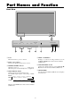
Part Names and Function Front View MENU/ENTER MENU/ENTER 7 VOLUME DOWN UP LEFT/- RIGHT/+ INPUT SELECT /EXIT VOLUME DOWN UP POWER/STANDBY LEFT/ - 6 RIGHT/+ INPUT SELECT /EXIT 5 4 q Power Turns the monitor’s power on and off. 1 3 2 t LEFT/– and RIGHT/+ Enlarges or reduces the image. Functions as the CURSOR ( / ) buttons in the On-Screen Menu (OSM) mode. w Remote sensor window Receives the signals from the remote control. y VOLUME DOWN and UP Adjusts the volume.
Rear View/ Terminal Board VIDEO VIDEO 1 (IN/OUT) VIDEO 2 VIDEO 3 C AUDIO 1 R (MONO) L D Y DVD1 / HD1 Cb/Pb E Cr/Pr AUDIO 2 R (MONO) L R/ Cr/Pr B/ Cb/Pb HD RGB2 / DVD2 / HD2 G/ Y F VD AUDIO 3 R (MONO) L AC IN RIGHT LEFT SPEAKERS MUST HAVE MORE THAN 7WATT RATING IMPEDANCE 6 OHM RGB 3 DV I ( Digital RGB ) H External Control IN AC REMOTE IN RIGHT LEFT SPEAKERS MUST HAVE MORE THAN 7WATT RATING IMPEDANCE 6 OHM OUT I J K RGB 1 (IN / OUT) G A A AC IN Connect the include
w RGB/PC Press this button to select RGB/PC as the source. The available sources depend on the setting of “BNC INPUT”. RGB: → RGB/PC1 → RGB/PC2 → RGB/PC3 Remote Control COMP. : OFF POWER RGB/PC ON RGB/PC can also be selected using the INPUT SELECT button on the monitor. DVD/HD e DVD / HD Press this button to select DVD/HD as the source. The available sources depend on the setting of “BNC INPUT”. RGB: HD/DVD/DTV VIDEO POSITION / CONTROL MENU/ENTER COMP.
!5 MULTI Not functional for the models covered in this manual. Battery Installation and Replacement Insert the 2 “AAA” batteries, making sure to set them in with the proper polarity. !6 SELECT Not functional for the models covered in this manual. 1.Press and open the cover.
Using the wired remote control mode Connect the remote cable* to the remote control’s remote jack and the “REMOTE IN” terminal on the monitor. When the cable is connected, the mode automatically switches to wired remote control. When the wired remote control mode is used, the remote control can be operated even if no batteries are loaded. Operating Range * Use the remote control within a distance of about 7 m/ 23ft.
Installation VCR or Laser Disc Player VIDEO 1 VIDEO ( I N / OUT) VIDEO 1- 3 VIDEO 2 VIDEO 3 To video inputs on the plasma monitor AUDIO 1 R (MONO) L Y Cb/Pb DVD1 / HD1 Document Camera Cr/Pr AUDIO 2 R (MONO) L R/ Cr/Pr B/ Cb/Pb HD RGB2 / DVD2 / HD2 G/ Y DVD Player VD IBM VGA or Compatibles RGB 1 ( I N / OUT) (MONO) AUDIO 3 R Macintosh or Compatibles L (Desk top type) RGB 3 DV I ( Digital RGB ) External Control Monitor adapter for Macintosh IN To Mini D-Sub 15 pin connector on
Connecting Your PC or Macintosh Computer Connecting Your Document Camera Connecting your PC or Macintosh computer to your plasma monitor will enable you to display your computer’s screen image for an impressive presentation. The plasma monitor supports the signals described on page 41. To connect a PC, Macintosh or compatible graphics adapter, simply: You can connect your plasma monitor to a document camera. To do so, simply: 1. Turn off the power to your plasma monitor and document camera. 2.
Pin Assignments and Signal Levels for 15 pin RGB (Analog) Pin Configuration and Signal of the RGB 3 Connector (DVI Connector) The unit is equipped with a type of connector commonly used for digital. (This cannot be used for an analog input.) (TMDS can be used for one link only.) 5 4 3 2 1 10 9 8 7 6 15 14 13 12 11 RGB 3 Pin No.
Creating a video wall With buit-in matrix display capability, you can create a 2×2 or 3×3 video wall. • Connect signal cables and remote cables as shown below.
Basic Operations POWER DIGITAL ZOOM To turn the unit ON and OFF: Digital zoom specifies the picture position and enlarges the picture. 1. Plug the power cord into an active AC power outlet. 1. Press the POINTER button to display the pointer. ( 2. Press the POWER ON button (on the remote control or control panel) to turn on the unit. ) To change the size of the picture: Press the ZOOM+ button and enlarge the picture. The pointer will change to resemble a magnifying ) glass.
OFF TIMER To cancel the off timer: To set the off timer: The off timer can be set to turn the power off after 30, 60, 90 or 120 minutes. 1. Press the OFF TIMER button twice in a row. 2. The off timer is canceled. OFF TIMER 1. Press the OFF TIMER button to start the timer at 30 minutes. 0 2. Press the OFF TIMER button to the desired time. 3. The timer starts when the menu turns off. → 30 → 60 → 90 → 120 → 0 Note: After the power is turned off with the off timer ...
WIDE Operations Wide Screen Operation (manual) STADIUM size screen With this function, you can select one of five screen sizes. When viewing videos or digital video discs 1. Press the WIDE button on the remote control. 2. Within 3 seconds ... The picture is expanded in the horizontal and vertical directions at different ratios. * Use this for watching normal video programs (4:3) with a wide screen. Press the WIDE button again.
Wide Screen Operation with Computer Signals Information 䡵 Supported resolution See page 41 for details on the display output of the various VESA signal standards supported by the monitor. Switch to the wide screen mode to expand the 4 : 3 image to fill the entire screen. 1. Press the WIDE button on the remote control. 2. Within 3 seconds ... Press the WIDE button again.
OSM(On Screen Menu) Controls Menu Operations 5. The adjustments or the settings that are stored in memory. The change is stored until you change it again. The OSM window is displayed with respect to the screen as shown on the diagram. 6. Repeat steps 2 – 5 to adjust an additional item, or press the EXIT button on the remote control to return to the main menu. * Depending on the screen’s mode, the OSM may be displayed differently. In the explanation, the OSM section is shown close up.
Main menu Sub menu Functions PICTURE CONTRAST BRIGHTNESS SHARPNESS COLOR TINT PICTURE MODE NR COLOR TEMP WHITE BALANCE GAIN RED GAIN GREEN GAIN BLUE BIAS RED BIAS GREEN BIAS BLUE RESET GAMMA LOW TONE COLOR TUNE RED GREEN BLUE YELLOW MAGENTA CYAN RESET Adjusts the contrast. Adjusts the brightness. Adjusts the sharpness. Adjusts the color. Adjusts the tint. Sets the picture mode according to the VIDEO environment and image software. Reduces noise visible in image.
Main menu Sub menu OPTION2 PWR. MGT. CINEMA MODE LONG LIFE Default Reset OFF ON AUTO OFF OFF OFF 3 Yes Yes Yes Yes Yes Yes Yes Functions Default Reset PWR. ON MODE CONTROL LOCK IR REMOTE LOOP OUT ID NUMBER VIDEO WALL DIVIDER POSITION DISP. MODE AUTO ID IMAGE ADJUST P. ON DELAY PLE LINK REPEAT TIMER Sets the day of the week and the time. Sets the ON/OFF time for switching on the power and the input mode. Sets the input mode at the time the power is switched on.
Picture Settings Menu Setting the picture mode according to the brightness of the room There are four picture modes that can be used effectively according to the environment in which you are viewing the display. Example: Setting the “THEAT. 1” mode Press the MENU/ENTER button on the remote control to display the MAIN MENU on the screen, then... Adjusting the picture The contrast, brightness, sharpness, color and tint can be adjusted as desired.
Reducing noise in the picture Use these settings if the picture has noise due to poor reception or when playing video tapes on which the picture quality is poor. Example: Setting “NR-3” Press the MENU/ENTER button on the remote control to display the MAIN MENU on the screen, then... Setting the color temperature Use this procedure to set color tone produced by the plasma display. Example: Setting “HIGH” Press the MENU/ENTER button on the remote control to display the MAIN MENU on the screen, then... 1.
5. Use the ▲ and ▼ buttons to select “GAIN RED”. 4. Once the setting is completed... Press the EXIT button to return to the main menu. To delete the main menu, press the EXIT button once more. WHITE BALANCE COLOR TEMP. HIGH GAIN RED GAIN GREEN GAIN BLUE BIAS RED BIAS GREEN BIAS BLUE RESET SEL. Information : ADJ. GAMMA settings The picture becomes darker as the number increases (in the sequence of 1, 2, 3, 4). OFF EXIT RETURN 6. Adjust the white balance using the and buttons.
Audio Settings Menu Adjusting the colors Use this procedure to adjust hue and color density for red, green, blue, yellow, magenta and cyan. Such adjustments will not affect the other colors. You can accentuate the green color of trees, the blue of the sky, etc. Example: Adjusting the color tune for blue Set “ADVANCED OSM” to “ON” in the MAIN MENU (1/2), then perform the following operations. Press the MENU/ENTER button on the remote control to display the MAIN MENU on the screen, then...
Image Adjust Settings Menu Setting the allocation of the audio connectors Setting the AUDIO 1, 2, and 3 connectors to the desired input. Example: Setting “AUDIO INPUT1” to “VIDEO 2” Press the MENU/ENTER button on the remote control to display the MAIN MENU on the screen, then... Adjusting the Position, Size, Fine Picture, Picture Adj The position of the image can be adjusted and flickering of the image can be corrected.
Option1 Settings Menu Information Setting the on-screen menu This sets the position of the menu, the display format (horizontal or vertical) etc. Example: Turning the DISPLAY OSM off Press the MENU/ENTER button on the remote control to display the MAIN MENU on the screen, then... When “AUTO PICTURE” is “OFF” IMAGE ADJUST ASPECT MODE : FULL V-POSITION H-POSITION V-HEIGHT H-WIDTH AUTO PICTURE : OFF FINE PICTURE PICTURE ADJ. EXIT RETURN SEL. ADJ. 1.
“V” Checking the signal being transmitted to RGB1 terminal Use this to confirm the signal being transmitted to the RGB1 terminal. It is set to RGB and can not be adjusted. OPTION1 OSM BNC INPUT : RGB D-SUB INPUT : RGB RGB SELECT : AUTO HD SELECT : 1080B INPUT SKIP : OFF ALL RESET : OFF 1024 768 SEL. MENU/ENTER OK EXIT RETURN OPTION1 OSM BNC INPUT : D-SUB INPUT : RGB SELECT : HD SELECT : INPUT SKIP : ALL RESET : NEXT PAGE CAN NOT ADJUST Only effective when Advanced OSM is OFF. OSM ORBITER settings ON .
4. Once the setting is completed ... Press the EXIT button to return to the main menu. To delete the main menu, press the EXIT button once more. Information RGB SELECT modes One of these 6 modes must be selected in order to display the following signals correctly. AUTO .............. Select the suitable mode for the specifications of input signals as listed in the table “Computer input signals supported by this system” on page 41. STILL .............. To display VESA standard signals.
Resetting to the default values Use these operations to restore all the settings (PICTURE, AUDIO, IMAGE ADJUST, OPTION1~3, etc) to the factory default values. Refer to page 16 for items to be reset. Press the MENU/ENTER button on the remote control to display the MAIN MENU on the screen, then... Option2 Settings Menu 1. Use the ▲ and ▼ buttons to select “OPTION1”, then press the MENU/ENTER button. The “OPTION1” screen appears.
䡵 Restoring the factory default settings Select “ALL RESET” under the OPTION1 menu. Note that this also restores other settings to the factory defaults. Reducing burn-in of the screen The brightness of the screen, the position of the picture, positive/negative mode and screen wiper are adjusted to reduce burn-in of the screen. Set “ADVANCED OSM” to “ON” in the main menu (1/ 2), then perform the following operations.
• H-DOT Information →1 DOT ↔ 2 DOT ↔ ..... ↔ 19 DOT ↔ 20 DOT← 䡵 PLE settings AUTO .............. The brightness of the screen is adjusted automatically to suit the picture quality. LOCK1, 2, 3 .... Sets maximum brightness. The brightness level decreases in the order of LOCK 1, 2, 3. LOCK 3 provides minimum brightness. • V-LINE →1 LINE ↔ 2 LINE ↔ ..... ↔ 19 LINE ↔ 20 LINE← • TIME →1 M ↔ 2 M ↔ 3 M ↔ 4 M ↔ 5 M← ORBITER H-DOT V-LINE TIME ORBITER Use this to set the picture shift.
Setting the time for INVERSE/WHITE Set a time duration. Example: Setting to that the INVERSE mode starts in 2 hours and proceeds for one hour and a half. Perform Steps 1-3 of INVERSE, then... 4. Use the 䊴 and 䊳 buttons to select “ON”, then press the MENU/ENTER button. THE “INVERSE/WHITE” screen appears. 5. Adjust the time using the ▲▼䊴 and 䊳 buttons.
Setting the gray level for the sides of the screen Use this procedure to set the gray level for the parts on the screen on which nothing is displayed when the screen is set to the 4:3 size. Example: Adjusting the “GRAY LEVEL” Set “ADVANCED OSM” to “ON” in the main menu (1/ 2), then perform the following operations. Press the MENU/ENTER button on the remote control to display the MAIN MENU on the screen, then... Information 䡵 Setting the time WORKING TIME ..... Set the time duration for “SCREEN WIPER”.
4. Use the ▲ and ▼ buttons to select the item, then adjust using the 䊴 and 䊳 buttons. Option3 Settings Menu Using the timer This function sets the monitor to turn ON/OFF automatically at a set time. Set “ADVANCED OSM” to “ON” in the main menu (1/ 2), then perform the following operations. Press the MENU/ENTER button on the remote control to display the MAIN MENU on the screen, then... PRESENT TIME RETURN DAYLIGHT SAVING TIME : OFF WEDNESDAY 22 : 05 : 00 SEL. EXIT RETURN ADJ. 1.
OFF (hour, minutes) ... Set the time at which the power will be turned off in the 24-hour format. INPUT ..................... Set the input mode that will be displayed when the timer is on. FUNCTION ............. Set the LONG LIFE function. PROGRAM TIMER This sets the day and time at which the power will be switched ON/OFF as well as the input mode. Example: Setting so that the power will be switched on at 8:30 A.M., Monday, displaying RGB2 source, and switched off at 10:30 A.M.
3/3 OPTION3 PREVIOUS PAGE TIMER PWR. ON MODE : VIDEO2 CONTROL LOCK : OFF IR REMOTE : ON LOOP OUT : OFF ID NUMBER : ALL VIDEO WALL EXIT RETURN SEL. ADJ. Information 䡵 CONTROL LOCK settings ON ...... Disables the buttons on the front panel. OFF .... Enables the buttons on the front panel. * Even when the CONTROL LOCK is set, the POWER switch will not be locked. * This becomes effective when the on-screen menu goes out. 4. Once the setting is completed... Press the EXIT button return to the main menu.
Loop Out setting When this feature is set to ON, the received signal will be looped out. Example: Setting “ON” Set “ADVANCED OSM” to “ON” in the main menu (1/ 2), then perform the following operations. Press the MENU/ENTER button on the remote control to display the MAIN MENU on the screen, then... 1. Use the ▲ and ▼ buttons to select “OPTION3”, then press the MENU/ENTER button. The “OPTION3” screen appears. 2. Use the ▲ and ▼ buttons to select “LOOP OUT”. 3. To set the LOOP OUT to “ON”...
Video Wall setting Use this feature to configure a 2×2 or 3×3 video wall. Set “ADVANCED OSM” to “ON” in the main menu (1/ 2), then perform the following operations. Press the MENU/ENTER button on the remote control to display the MAIN MENU on the screen, then... VIDEO WALL DIVIDER : POSITION DISP. MODE : AUTO ID : IMAGE ADJUST P. ON DELAY : PLE LINK : REPEAT TIMER : SEL. ADJ. 1. Use the ▲ and ▼ buttons to select “OPTION3”, then press the MENU/ENTER button. The “OPTION3” screen appears.
DISP. MODE Select the screen mode from between two options (Splitting, Blanking). Example: Setting “BLANK” Information 䡵 AUTO ID settings ON ...... Enables Auto ID function. In the case shown below, display 1 will be set as ID 1, display 2 as ID2, etc. Perform Steps 1-2 of VIDEO WALL, then... 3. Use the ▲ and ▼ buttons to select “DISP. MODE”. 4. Use the 䊴 and 䊳 buttons to select “BLANK”.
P. ON DELAY (Power on delay) Use this function to activate power-on delay. Turn on the AUTO ID before the following operations. Example: Setting “ON” PLE LINK Use this function to set a uniform brightness for each display. Turn on the AUTO ID before the following operations. Example: Setting “ON” Perform Steps 1-2 of VIDEO WALL, then... Perform Steps 1-2 of VIDEO WALL, then... 3. Use the ▲ and ▼ buttons to select “P. ON DELAY”. 4. Use the 䊴 and 䊳 buttons to select “ON”.
REPEAT TIMER Use this to set two timers. Each timer can use the DIVIDER, SOURCE and WORK TIME functions. Turn on the AUTO ID before the following operations. Example: TIMER1...VIDEO1 will be displayed for 3 minutes. TIMER2...RGB1 will be displayed for 6 minutes in a 2×2 video wall. Perform Steps 1-2 of VIDEO WALL, then... 3. Use the ▲ and ▼ buttons to select “REPEAT TIMER”. Advanced OSM Settings Menu Setting the menu mode This allows you to access full menu items. When P.
→ ENGLISH ↔ DEUTSCH ↔ FRANÇAIS ← → Information ↔ SVENSKA ↔ ITALIANO ↔ ESPAÑOL ← 䡵 Video signal formats Different countries use different formats for video signals. Set to the color system used in your current country. AUTO .............. The color systems are automatically identified and the format is set accordingly. PAL .................. This is the standard format used mainly in the United Kingdom and Germany. SECAM ............. This is the standard format used mainly in France and Russia. 4.
External Control Application External Control Codes (Reference) These specifications cover the communications control of the plasma monitor by external equipment. Connections Connections are made as described below. External equipment e.g., Personal computer Display Connector on the plasma monitor side: EXTERNAL CONTROL connector. Use a crossed (reverse) cable.
Table of Signals Supported 42VP4/42VP4D Supported resolution • When the screen mode is NORMAL, each signal is converted to a 640 dots 480 lines signal (42VP4/42VP4D). (Except for *2, *4) • When the screen mode is FULL, each signal is converted to a 853 dots 480 lines signal (42VP4/42VP4D).
*1 Only when using a graphic accelerator board that is capable of displaying 852 480. *2 Display only 400 lines (42VP4/42VP4D) with the screen center of the vertical orientation located at the center. *3 42VP4/42VP4D: The picture is displayed in the original resolution. The picture will be compressed for other signals. *4 Aspect ratio is 5:4. This signal is converted to the following signal (42VP4/42VP4D: 600 dots 480 lines). *5 Normally the RGB select mode suite for the input signals is set automatically.
Troubleshooting If the picture quality is poor or there is some other problem, check the adjustments, operations, etc., before requesting service. Symptom Checks Picture is disturbed. • Is a connected component set directly in Sound is noisy. front or at the side of the display? Remote control operates erroneously. The remote control does not work.
*1 Overheat protector If the monitor becomes too hot, the overheat protector will be activated and the monitor will be turned off. If this happens, turn off the power to the monitor and unplug the power cord. If the room where the monitor is installed is particularly hot, move the monitor to a cooler location and wait for the monitor to cool for 60 minutes. If the problem persists, contact your dealer.
Specifications 42VP4/42VP4D Color Reproduction Signals Synchronization Range Input Signals 2.32" (59) 36.3" (921) Horizontal : 15.5 to 110 kHz (automatic : step scan) Vertical : 50.0 to 120 Hz (automatic : step scan) RGB, NTSC (3.58/4.
46
47
Limited Warranty Plasma Monitors NEC Solutions, Inc. (hereinafter NEC Solutions) warrants this product to be free from defects in material and workmanship under the following terms and, subject to the conditions set forth below, agrees to repair or replace (at NEC Solutions’ sole option) any part of the enclosed unit which proves defective. Replacement parts or products may be new or refurbished and will meet specifications of the original parts or products.
NEC Solutions (America), Inc. 1250 N.