English User’s Manual EXIT PlasmaSync 42XP10 PlasmaSync 50XP10 PlasmaSync 60XP10 INPUT MUTE
Package Contents • Plasma Monitor • Remote control and AA Batteries • Power cord • Users Manual (CD-ROM) • Start Up Guide (Paper / CD-ROM) • Main Power Switch cover and screw • Cable clamps
Table of Contents Important Safety Instructions ..............................................................................................................English-1 Important Information ...........................................................................................................................English-2 Safety Precautions and Maintenance ...................................................................................................English-3 Recommended Use .............................
Important Safety Instructions 13. Unplug this apparatus during lightning storms or when unused for long periods of time 14. Refer all servicing to qualified service personnel. Servicing is required when the apparatus has been damaged in any way, such as when the power-supply cord or plug is damaged, liquid has been spilled or objects have fallen into the apparatus, the apparatus has been exposed to rain or moisture, does not operate normally, or has been dropped 16.
Important Information TO PREVENT FIRE OR SHOCK HAZARDS, DO NOT EXPOSE THIS UNIT TO RAIN OR MOISTURE. DO NOT USE THIS UNIT’S POLARIZED PLUG WITH AN EXTENSION CORD RECEPTACLE OR OTHER OUTLETS UNLESS THE PRONGS CAN BE FULLY INSERTED. REFRAIN FROM OPENING THE CABINET AS THERE ARE HIGH VOLTAGE COMPONENTS INSIDE. REFER SERVICING TO QUALIFIED SERVICE PERSONNEL. CAUTION CAUTION: TO REDUCE THE RISK OF ELECTRIC SHOCK, MAKE SURE POWER CORD IS UNPLUGGED FROM WALL SOCKET.
Safety Precautions and Maintenance • Unplug the power cord during electrical storms or when the unit will not be in use for a long period. • Do not use monitor in high temperature, humid, dusty, or oily areas. • Do not cover vent on monitor. • Clean plasma ventilation areas using a vacuum cleaner with a soft brush nozzle attachment. • To ensure proper ventilation, cleaning the ventilation areas must be carried out monthly.
Recommended Use Cleaning the Panel • When the panel becomes dusty or dirty, wipe gently with soft cloth. • Do not rub the panel with coarse material. • Do not apply pressure to the surface. • Do not use OA cleaner. OA cleaner will cause deterioration or discolor the surface. CORRECT PLACEMENT AND ADJUSTMENT OF THE MONITOR CAN REDUCE EYE, SHOULDER AND NECK FATIGUE. CHECK THE FOLLOWING WHEN POSITIONING THE MONITOR: • For optimum performance, allow 20 minutes for warmup.
Recommended Use - continued To avoid or minimize image retention: OPERATING ENVIRONMENT Operating environment temperature and humidity: 0 °C to +40 °C (+32 °F to +104 °F); less than 80%RH (cooling vents not blocked) Do not install this unit in a poorly ventilated area, or in locations exposed to high humidity or direct sunlight (or strong artificial light) Like all phosphor-based display devices and all other gas plasma displays, plasma monitors can be susceptible to image retention under certain circumst
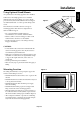
Installation An optional stand or mounting apparatus can be installed . Optional table top stand When stand or mounting apparatus is to be installed while the unit is face-down (Figure 1), be sure to lay the protective sheet (the foam sheet that the unit was wrapped in) underneath the unit on order to prevent damage to the screen. Figure 1 This unit must be used with a stand or some type of mounting apparatus. This unit is not designed for use without additional support.
Installation - continued Mounting on Ceiling • Ensure that the ceiling is sturdy enough to support the weight of the unit and the mounting apparatus over time, against earthquakes, unexpected vibrations, and other external forces. • Be sure the unit is mounted to a solid structure within the ceiling, such as a support beam. Secure the monitor using bolts, spring lock washers, washer and nut. • DO NOT mount to areas that have no supporting internal structure.
Installation - continued Point the top of the remote control toward the monitor’s remote sensor while pressing buttons. The remote control can be used from the front of the monitor at a maximum distance of 7 m/23 ft. from the front of the Plasma monitor’s remote control sensor. The maximum horizontal and vertical angle for use of the remote is 30 degree within a distance of 3.5 m/11.5 ft. Install the remote control batteries. The remote control is powered by AA batteries.
Part Names and Functions Control Panel 9 EXIT ON INPUT MUTE OFF 10 8 7 6 5 1) POWER Switches the power on/standby. 4 3 2 1 8) EXIT Activates the OSD menu when the OSD menu is off. Exits from the current menu being displayed to the previous menu within the OSD. 2) MUTE Switches the audio mute ON/OFF. 9) Remote control sensor and Power indicator Receives the signal when using the wireless remote control. Glows green when the monitor is active. Glows red when the monitor is in Standby mode.
Part Names and Functions English Terminal Panel 1 12 OUT HD VD R R IN EXTERNAL CONTROL 2 R IN R L(MONO) S-VIDEO IN IN/OUT DVI AUDIO3 VGA RGBHV / DVD/HD2 AUDIO2 DVD/HD1 AUDIO1 VIDEO 3 4 5 6 7 8 9 L (MONO) R/Cr/Pr G/Y B/Cb/pb 1) EXTERNAL CONTROL OUT (D-Sub 9 pin) Connect RS-232C output to a second monitor. 2) EXTERNAL CONTROL (D-Sub 9 pin) Connect RS-232C input to external equipment such as a PC in order to control RS-232C functions.
Part Names and Functions - continued Remote Control Functions 7) KEYPAD Set REMOTE ID. 1 2 3 4 5 POWER ON STANDBY RGB DVD/HD PICTURE MEMORY PICTURE MODE SIZE VIDEO 8) DISPLAY Turn on/off the Information OSD. 9) Move selection up or down 6 1 2 3 4 5 6 7 8 9 10) AUTO SETUP Adjusts the CLOCK PHASE, CLOCK, and POSITION settings automatically. (Analog RGB signal input only) 7 11) POINTER Turn on/off the pointer.
Part Names and Functions - continued Included with the display is a cover for the Main Power Switch. Use this cover to prevent the unit from being inadvertently powered off. To turn the unit ON and OFF: 1. Plug the power cord into an AC outlet. Place the tab on the cable cover into the rectangular slot on the display. 2. Press the Power button (on the unit). The monitor's ON/STANDBY indicator turns red and the unit will be in STANDBY mode. Then using the screw provided, secure the cover to the display.
Part Names and Functions - continued Remote Control ID Function REMOTE CONTROL ID The remote control included with the display can be used to control up to 26 individual monitors using what is called the REMOTE CONTROL ID mode. The REMOTE CONTROL ID mode works in conjunction with the Monitor ID, allowing control of up to 26 individual monitors. For example: if there are many monitors being used in the same area, a remote control in normal mode would send signals to every monitor at the same time Figure 1.
4. Change the setting or adjustment by pressing the + and - buttons on the Control Panel or the Remote Control. Using the OSD Use the Remote Control or the control panel on the front of the unit to enter the on-screen display menu to adjust settings. 5. Press the EXIT button on the Remote Control, on the Control Panel to return to the previous menu. NOTE: Not all menu functions may be available. To access all functions the Advanced OSD option must be turned on in the ADVANCED OSD menu. 1.
On-Screen Display (OSD) Main Menu Sub Menu Default Reset PICTURE CONTRAST Sub Menu2 Sub Menu3 Explanation Adjusts the image brightness in relationship to the white level. Press + or - to adjust. 50 YES BRIGHTNESS Adjusts the image brightness in relationship to the background. Press + or - to adjust. 50 YES SHARPNESS Adjusts the crispness of the image. Press + or - to adjust. 50 YES COLOR Adjusts the color depth of the screen. Press + or - to adjust.
Main Menu Sub Menu SCREEN ASPECT MODE Selects aspect ratio of the displayed image. Press + or - to select. V-POSITION OPTION1 Sub Menu2 Sub Menu3 Explanation Default Reset Controls the vertical position of the image within the Display area of the PDP. Press + to move up. Press - to move down. 0 YES H-POSITION Controls the horizontal position of the image within the Display area of the PDP. Press + to move right. Press - to move left. 0 YES V-HEIGHT Adjusts the vertical size of the image.
On-Screen Display (OSD) Main Menu Sub Menu Default Reset OPTION2 Available only when the Advanced OSD function is enabled. POWER SAVE Sub Menu2 Sub Menu3 Sets how long the monitor waits before going into power save mode after a signal is lost. VGA, RGBHV, and DVI input and Separate HV Sync. only. OFF YES FILM MODE Selects Film mode. ON YES SCREEN SAVER Use SCREEN SAVER functions to reduce the risk of image retention. PLE PLE: The brightness is decreased in order of Lock mode.
Main Menu Sub Menu OPTION3 VIDEO WALL Sub Menu2 Sub Menu3 Explanation Default Reset OFF YES SPLIT YES V-POSITION 0 YES H-POSITION 0 YES V-HEIGHT 0 YES H-WIDTH 0 YES AUTO PICTURE OFF YES CLOCK PHASE 0 YES CLOCK 0 YES UNDER SCAN OFF YES OFF YES AUTO YES Sets the configuration of video wall. (continued) DIVIDER POSITION Sets the position of each display. DISP. MODE Sets the mode of seam processing for each display. SCREEN P.
Operation 2.35:1 Image is expanded at a 2.35:1 ratio to fill the entire screen. The screen is filled vertically; however, some information will be lost on the left and right sides of the image. Picture Size Using Video Signals Select one of seven picture sizes manually. While viewing videos or digital video discs, perform the following actions: Available for the following inputs: Video, Component, or RGB input (480I, 480P, 576I, 576P, 720P, 1080I, 1080P) 1. Press the SIZE button on the remote control. 2.
TRUE The image is displayed at the native resolution. Picture Size Using Computer Signals When using a VGA or SVGA signal, PICTURE SIZE in the OPTION 2 OSD menu should be set to OFF to select TRUE mode. To expand a 4:3 image to fill the entire screen, switch to the widescreen mode. While viewing videos or digital video discs, perform the following actions: 1. Press the SIZE button on the remote control. 2. To switch the screen sizes, press the SIZE button again within 3 seconds.
Operation - continued Press the SWAP button to swap pictures. Split Screen Mode To display multiple pictures on the screen, perform the following actions: VGA A B 1. Press the desired SPLIT SCREEN function button on the remote (PIP, S BY S, SINGLE). SWAP Only certain RGB signals are supported. VGA B A SINGLE button PIP button S BY S button A SINGLE button PIP button VGA A Press the SELECT/FREEZE button to change the active picture. VGA A B VGA B VIDEO1 is active.
Picture-in-Picture Mode Displaying Input Signal Press the + and - buttons to change the position of the subpicture. 1. To make the desired picture active, press the SELECT/ FREEZE button. + button VGA B 2. To change the active signal, press the VIDEO, DVD/HD, or RGB button. VGA A B A The input selection may also be changed by pressing the INPUT button on the front of the unit. button button + button button VGA B + button button Adjusting the OSD controls VGA A A 1.
Operation - continued Creating a Video Wall Video Signal You can create a video wall consisting of up to 25 individual monitors with the built-in matrix display capability. Your Video Wall can have any of the following configurations: 2x2, 3x3, 4x4, 5x5, 5x1, 4x1, 3x1, 2x1, 1x2, 1x3, 1x4, or 1x5.
Using special characters in the PROGRAM TIMER setting. USING THE TIMER Turn the “ADVANCED OSD” to “ON” in the MAIN MENU to access the TIMER feature in OPTION3. Using an asterisk (*) alone in the DAY field means that the programmed schedule will run every day. Using the asterisk (*) and the name of the day means the programmed schedule will run only on that day. For example "*FRI" means that the schedule will run every Friday.
Operation - continued REPEAT TIMER The Repeat Timer allows the display to alternate between inputs at user-determined intervals. For example the display can be programmed to show the signal from "VIDEO1" for 10 minutes and then switch to showing the signal from the DVI input for 10 minutes. To set the Repeat Timer select "REPEAT" in the Timer menu, then press the SET button. To enter the REPEAT TIMER OSD screen. Then make the desired settings. STATE Settings There are 4 possible state settings to use.
RS-232C This Plasma monitor can be controlled via personal computer using an RS-232C connection. • Powering ON or OFF • Switching input signals MONITOR ID and RS-232C CONTROL NOTE: If your PC (IBM or IBM compatible) is equipped only with a 25-pin serial port connector, a 25-pin serial port adapter is required. Contact your dealer for details. Up to 26 individual monitors can be controlled through a daisy chain via RS-232C connection. 1. Connect PC to the monitor.
RS-232C - continued The following control sequence is used for a single monitor When using the following control commands, all of the daisy-chained monitors can be controlled at the same time from the primary monitor. However, reply and status commands will only pertain to the primary monitor, and not to the secondary monitors.
RS-232C - continued 1) The command from a computer to the Plasma monitor will take 400ms. 2) The Plasma monitor will send a return command 400ms* after it has received an encode. If the command is not received correctly, the Plasma monitor will not send the return command. 3) The personal computer checks the command and confirms if the command which has been sent has been executed or not. 4) This Plasma monitor sends various codes other than the return code.
RS-232C - continued 5) Read command Host computer sends the command without Data-code to monitor. After receiving this command, the monitor returns the command with Data-code of current status to host computer. When the Host computer checks the Power status of monitor, the status of monitor is powered-on. Command from computer Command from Monitor 30 30 76 50 0D ‘0’’0’’v’’P’[enter] Detail of command Ask about the power status of monitor.
Troubleshooting Display image is not sized properly • Use the OSD screen controls to increase or decrease the clock total. • Check to make sure that a supported mode has been selected on the display card or system being used. (Please consult display card or system manual to change graphics mode.) • The signal cable should be properly connected to the display card/computer. • The display card should be properly seated in its slot. • Front Power Switch and computer power switch should be in the ON position.
Specifications P42XP10 PDP Module Frequency Diagonal: 42 "/1058 mm Pixel Pitch 0.900 mm (W)/0.676 mm (H) Resolution 1024 x 768 Horizontal ANALOG: 15.625/15.734kHz, 31.0kHz - 108.5kHz Vertical 24Hz to 120.4Hz DIGITAL: 15.625/15.734kHz, 31.0kHz - 91.1kHz Panel Display Size 922 mm (W) x 519 mm (H) 36.3 in (W) x 20.4 in (H) Input Signals DVI DVI-D 24pin Digital RGB DVI (HDCP) VGA60, SVGA60, XGA60, WXGA60, SXGA60, UXGA60*, 1920X1080* VGA 15pin Mini D-sub Analog RGB 0.
Specifications P50XP10 Frequency Diagonal: 50"/1269 mm Pixel Pitch 0.81 mm (W)/0.81 mm (H) Resolution 1365 x 768 Horizontal ANALOG: 15.625/15.734kHz, 31.0kHz - 108.5kHz Vertical 24Hz to 120.4Hz DIGITAL: 15.625/15.734kHz, 31.0kHz - 91.1kHz Panel Display Size 1106 mm (W) x 622 mm (H) 43.5 in (W) x 24.5 in (H) Input Signals DVI DVI-D 24pin Digital RGB DVI (HDCP) VGA60, SVGA60, XGA60, WXGA60, SXGA60, UXGA60*, 1920X1080* VGA 15pin Mini D-sub Analog RGB 0.
Specifications P60XP10 PDP Module Frequency Diagonal: 60"/1514 mm Pixel Pitch 0.966 mm (W)/0.966 mm (H) Resolution 1366 x 768 Horizontal ANALOG: 15.625/15.734kHz, 31.0kHz - 108.5kHz Vertical 24Hz to 120.4Hz DIGITAL: 15.625/15.734kHz, 31.0kHz - 91.1kHz Panel Display Size 1320 mm (W) x 742 mm (H) 51.9 in (W) x 29.2 in (H) Input Signals DVI DVI-D 24pin Digital RGB DVI (HDCP) VGA60, SVGA60, XGA60, WXGA60, SXGA60, UXGA60*, 1920X1080* VGA 15pin Mini D-sub Analog RGB 0.
English-34 EWS Series Apple Macintosh® IBM PC/AT Compatible Computers NORMAL (4:3) 768 pixels x 768 lines SGI HP SUN -- 1920 X 1200 1920 X 1200RB 640 X 480 832 X 624 1024 X 768 1152 X 870 1440 X 900 Work Station 1280 X 1024 1280 X 1024 1152 X 900 1152 X 900 1280 X 1024 1024 X 768 1280 X 1024 Wide-UXGA Wide-UXGA Mac13" Mac16" Mac19" Mac21" Apple17 EWS4800 Wide-SXGA UXGA 1680 X 1050 1600 X 1200 1920 X 1080 SXGA+ Wide-XGA 1280 X 768 1400 X 1050 XGA 1152 X 864 Wide-XGA Wide-XGA SXGA XGA 10
Composite / S Digital (EIA/CEA-861) RGB(Video signal) Y,Pb(Cb),Pr(Cr) Video English-35 NORMAL(4:3) 768 pixels x 768 lines -- Resolution HXV 3.58NTSC 4.
English-36 EWS Series Apple Macintosh® IBM PC/AT Compatible Computers Wide-VGA Wide-VGA SVGA XGA XGA Wide-XGA Wide-XGA Wide-XGA Wide-XGA Wide-XGA Wide-XGA SXGA SXGA+ Wide-SXGA UXGA Wide-UXGA Wide-UXGA Mac13" Mac16" Mac19" Mac21" Apple17 EWS4800 848 X 480 852 X 480 800 X 600 1024 X 768 1152 X 864 1280 X 768 1280 X 800 1280 X 854 1280 X 960 1360 X 768 1376 X 768 1280 X 1024 1400 X 1050 1680 X 1050 1600 X 1200 1920 X 1200 1920 X 1200RB 640 X 480 832 X 624 1024 X 768 1152 X 870 1440 X 900 W
English-37 NORMAL (4:3) 1024 pixels x 768 lines -- Resolution HXV 3.58NTSC 4.
English-38 EWS Series Apple Macintosh® IBM PC/AT Compatible Computers NORMAL (4:3) 1024 pixels x 768 lines SGI HP SUN -- 1920 X 1200 1920 X 1200RB 640 X 480 832 X 624 1024 X 768 1152 X 870 1440 X 900 Work Station 1280 X 1024 1280 X 1024 1152 X 900 1152 X 900 1280 X 1024 1024 X 768 1280 X 1024 Wide-UXGA Wide-UXGA Mac13" Mac16" Mac19" Mac21" Apple17 EWS4800 Wide-SXGA UXGA 1680 X 1050 1600 X 1200 1920 X 1080 SXGA+ Wide-XGA 1280 X 768 1400 X 1050 XGA 1152 X 864 Wide-XGA Wide-XGA SXGA XGA 1
Composite / S Digital (EIA/CEA-861) RGB(Video signal) Y,Pb(Cb),Pr(Cr) Video English-39 NORMAL (4:3) 1024 pixels x 768 lines -- Resolution HXV 3.58NTSC 4.
Pin Assignment 1) Analog RGB Input (Mini D-SUB 15P) VGA English 3) RS-232C Input (D-SUB 9P) Pin No. Name 1 Video Signal Red Pin No.
WEEE Mark (European Directive 2002/96/EC) Within the European Union EU-wide legislation, as implemented in each Member State, requires that waste electrical and electronic products carrying the mark (left) must be disposed of separately from normal household waste. This includes monitors and electrical accessories, such as signal cables or power cords.