855-900549-A Rev. 1 NX7700i/5020M-16 Operation Manual CAUTION Before using the product, be sure to read this manual and strictly adhere to the instructions. Keep this manual at hand for quick reference as required. ©NEC Corporation 2006 This manual cannot be duplicated or revised without permission from NEC Corp. The contents of this manual may be changed without prior notice.
Notes on export This product (including software) may be classified into the cargo (or service) to which the Foreign Exchange and Foreign Trade Control Law is applied. If this is the case, an export permit issued by the Government of Japan is required. If you need materials to help go through the process of applying for an export permit, consult your delivery agent or the nearby NEC branch office.
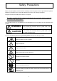
Safety Precautions Before using the product, read this manual carefully to ensure the proper and safe operation of the product. Follow the instructions in this manual to avoid physical injuries and damages to property. Keep this manual at hand for quick reference as required. The cables supplied with this product are designed to be used solely for this product. Do not use them for other purposes.
WARNING Do not touch the internal components of the equipment Nobody except the maintenance personnel should open the door of the equipment. Do not disassemble, repair or remodel the equipment by yourself. Do not touch the components inside the equipment or peer into the equipment while the maintenance personnel opened the door for service work. Failure to follow the instruction may result in electric shock or injury due to abnormal operation of the equipment.
Handling of the laser product A laser product of Class 1, Subchapter J, Chapter 1 of JIS C6802, EN60825, IEC825 and FDA21CFR, is used for this equipment.
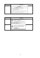
140 150 163 注※意:同型同定格のヒューズと交換すること。 CAUTION:For continued protection against risk of fire, replace only with same type and ratings of fuse. ATTENTION:Pour une protection continue contre l'incendie,remplacer les fusibles par ceux de meme type et de meme amperage. 注※意:資格者のみ保守すること。 HAZARD AREA:QUALIFIED SERVICE PERSONNEL ONLY DANGER:RESERVE SEULEMENT AU PERSONNEL 矢印を上に向けて取り付けること。 Install with arrow pointing upwards. Monter de maniere a orienter la fleche vers le haut.
243 416 注※意:カバーを開ける前に入力電源(分電盤)切断のこと。 CAUTION: Disconnect input power before removing this cover. ATTENTION:Couper l'alimentation electrique avant de demonter ce capot. 注※意:保守時は安定板を引き出すこと。 CAUTION: PULL OUT STABILIZER WHEN MAINTAINING. AT T E N T I O N : TIRER LE STABILISIEREN.
133-314121-GRP 051 MARKINGS 保守者の方へ 警告 WARNING 複数の装置を 同時に引き出さないで下さい。 ラックの破損、転倒などの事故の原因となります。 D o n o t p ul l o u t m or e tha n o n e c o m p o n e n t a t a ti m e as i t m ay ca u se d a m e g e to th e r a ck or a ll o w th e r ack to ti p o v er. 052 保守者の方へ 警告 WARNING 装置を引き出したり、装置の積み下ろしを行う際は、必ずラック前面 にあるスタビライザを引き出し確実に設置してから作業を行ってください。 スタビライザを引き出さないまま作業を行うと、ラックの破損、転倒など事故の原因となります。 Always extract and install the stabilizers when pulling out ore unloading components from the rack.
243-304367-GRP MARKINGS 001 243-306629-GRP MARKINGS 001 002 viii
Preface This document explains how to operate the hardware of the base module, the main body of this system. It is recommended that the related documents be read in order to make the best use of the above-mentioned system. Special techniques are necessary for installing and expanding the system. Please consult our sales personnel. Rev. 1, May 2006 Notes: (1) All rights reserved. This document cannot be reprinted or reproduced partly or entirely without permission from NEC Corp.
Contents Chapter 1 NX7700i/5020M-16 System Overview .................................................................1-1 1.1. Configuration and Specifications of the Base Module ...............................................1-2 1.2. Expandability .............................................................................................................1-6 1.2.1. Adding Processors...............................................................................................1-6 1.2.2.
2.4.6.4. 2.4.6.5. 2.4.6.6. 2.4.6.7. 2.4.6.8. 2.4.6.9. 2.4.6.10. 2.4.6.11. 2.4.6.12. 2.4.6.13. 2.4.6.14. 2.4.6.15. DT (SP Data and Time) ..............................................................................2-37 EN (Environmental Information) .................................................................2-38 FV (Firmware Versions) .............................................................................2-44 HC (Hardware Configuration)...........................................................
NX7700i/5020M-16 System Overview Chapter 1 NX7700i/5020M-16 System Overview This system is a server that implements the following by using the high performance Intel Itanium2 processor: • High processing capability • Open system using the industry standard architecture • Advanced system management and RAS function • High system expandability with a host of optional products 60 0 1975 or 1800 or 1620 or 1265 1 0 02 (a) Perspective View (Front) Figure.
NX7700i/5020M-16 System Overview 1.1. Configuration and Specifications of the Base Module The base module of this system is composed of the following hardware components: − CELL Can install one to four Intel Itanium2 processors. The minimum required memory capacity is 2GB and can be expanded up to 128GB. − I/O MODULE Can contain: Up to 8 PCI cards A DVD-ROM unit A DAT unit Up to 4 HDDs (up to two HDDs when DAT is used) − POWER BAY Can contain to 3 DPSs (AC/DC converters).
NX7700i/5020M-16 System Overview Front View I/O MODULE POWER BAY FAN BOX Rear View DPS FAN BOX AC SW Figure.
NX7700i/5020M-16 System Overview Table. Base Module Specifications BASE MODULE Cell (Max. 2 cells can be installed in the base module.) CPU Max. No. of processors 8 (Max. 4 processors/cell) Main memory Expansion unit 2GB/4GB/8GB Main memory capacity 2GB to 128GB I/O module (Max. 2 modules can be installed.) Max. No. of PCI slots 16 slots (133MHz) Max. I/O bandwidth 67GB/s DVD-ROM unit One unit can be installed in the I/O module.
NX7700i/5020M-16 System Overview Table. Base Module Specifications (Cont’d) Main Cabinet Cabinet size/weight Note 2) Width 600mm Height Depth Note 1) Weight (in max. configuration) 1265/1620/1975mm 1050mm 545Kg Power supply Voltage Single-phase, 200 to 240V±10% Frequency 50/60Hz±1Hz Power consumption (in max. configuration) 13.
NX7700i/5020M-16 System Overview 1.2. Expandability This section explains the expandability of this system and available configurations. CAUTION 1.2.1. Contact the maintenance personnel of NEC to replace or upgrade the system. Adding Processors At least one processor is required for the base module. Using the CPU expansion feature, the Itanium2 processor can be added one by one. Up to four processors can be installed for each cell.
NX7700i/5020M-16 System Overview BASE MODULE The minimum 2GB memory can be expanded up to 64GB for each cell. Itanium2 SP Console (Standard) CELL RS232C(Console) Ethernet cable Server management LAN interface 10/100Base - TX DVD-ROM UNIT N E C DAT UNIT I/O MODULE POWER BAY 0 Expansion POWER BAY * The expansion power bay is mounted only when the power is supplied from two systems or 100VAC. POWER BAY 1 Figure.
Base Module Chapter 2 Base Module This chapter covers operations required on the base module of this system. Locking/unlocking the cabinet Back door Front door Figure.
Base Module 2.1. Partition Function The base module has the partition function which enables the system to operate as if multiple units are present on one unit. The system is capable of partitioning in units of the cell or I/O module within the same base module. For example, in a system consisting of two cells and two I/O modules, partitioning shown in the figure below is possible. Note that each partition should contain at least one cell card and one I/O module (including the core module).
Base Module 2.2. Name and Function of Components 2.2.1. Cabinet (Primary Cabinet) The base module and expansion power bay (POWBAY#1) are installed in the cabinet. The number of installable base modules depends on the size of the cabinet. A maximum of four base modules can be installed in the largest cabinet. The example below shows that the system is installed in the 1620mm high cabinet. M-zz indicates “U” (unit size) from the bottom is zzU [1U is about 44mm].
Base Module 2.2.2 Base Module A base module is composed of cells, iSP cards, I/O modules, power bays, and DPSs. 2.2.3 Expansion Power Bay The expansion power bay is used only when the power is supplied from two systems or 100VAC. It is never used for a single power supply system. 2.2.4 Cell A cell is composed of up to four processors, a CPU node controller, a memory controller, and main memory. The main memory can vary from the minimum 2GB to the maximum 64GB.
Base Module 2.2.6. Power Bay The power bay supplies power to the system. A maximum of three DPSs (a DPS is a system power supply with a fan) can be installed in the power bay. The expansion power bay is used only when the power is supplied from two systems or 100VAC.
Base Module 2.2.7. iSP One iSP-C card is mounted on the base module as standard equipment. It contains the following interfaces: 1) 2) 10/100Base-TX Ethernet interface (x1) for SP console Serial (RS-232C) interface (x1) for SP console The iSP-C card is shown below. 8 7 6 5 4 3 2 1 DSW1 (RSC232C) CNSL DSW0 LAN1 LAN0 (7) PCIBAY6 Figure.
Base Module 2.2.8. DVD-ROM Unit One DVD-ROM unit can be installed for each I/O module. A DVD-ROM unit is mounted on each I/O module as standard equipment. The DVD-ROM and CD-ROM media can be used on the DVD-ROM unit. 2.2.8.1. Loading and Unloading Media (1) Loading DVD-ROM/CD-ROM 1) 2) 3) 4) Open the front cover, and remove the mask. (loosen the hand screw). Push the Eject button lightly, and the tray pops out. Place DVD-ROM/CD-ROM securely on the tray.
Base Module 2.2.9. DAT Unit An optional DAT unit can be installed in the I/O module. 2.2.9.1. Location of Index Labels The figure below shows the location of index labels attached to the digital audio tape. NEC Figure. 2.2.9.2. Index Labels on the Digital Audio Tape Notes on Index Labels (1) Attach index labels properly as shown in 2.2.9.1. Be sure to write the start date on these labels. (2) Change the labels when the DAT is used for other purpose.
Base Module 2.2.9.4. Cleaning the DAT Unit Wipe off the dusts on the DAT unit. See 2.2.9.5 to 2.2.9.7 for how to clean the DAT unit. 2.2.9.5. Cleaning Schedule How often the DAT unit should be cleaned depends on the operating environment. The table below will be of some help.
Base Module 2.2.9.9. Notes on the DAT Unit Avoid placing the DAT unit in the following locations as much as possible to prevent trouble in the DAT unit: • Near the printer (to prevent toner or paper powder dusts) • By the window or near the passage way (to prevent soil dusts) • On the carpet (to prevent dust generation) 2.2.9.10. Loading and Unloading Digital Audio Tapes How to load and unload a digital audio tape is explained below.
Base Module 2.2.10. Notes on Installing the UPS To installed the UPS, remove the signal cable for power control (on/off), and mount a jumper connector (shown in the figure below). This system has three forms of power supplies [a), b) and c) below]. It should be noted that the location of the jumper connector differs depending on the form of power supply. Figure.
Base Module b) Power supply from two systems Location on the inlet box: P1 AC SW P1 Location on the expansion power bay: P3 CB1 c) Power supply from 100VAC Location on the inlet box: P1 AC SW P1 Location on the expansion power bay: P5, P6, P7 P5 855-900549 P6 P7 AC SW 2-12 P3
Base Module 2.2.11. System LEDs System LEDs are located at the upper left of the front panel of the base module and indicate the system status. The views when the front panel is opened (a) and closed (b) are shown below.
Base Module 2.3. Consoles The base module contains console interfaces as standard equipment. The consoles connected to the interfaces provided by the iSP are roughly classified into two: • OS console (also called the system console or SW console) to display BIOS/OS messages • SP console (also called the HW console) to display SP messages 2.3.1.
Base Module BASE MODULE CELL CARD SYS BP I/O MODULE iSP-C CARD LAN CRT MOUSE/ KEYBOARD Console PC OS console OS console SP console RS232C modem modem ALIVE console Figure.
Base Module 2.4. Service Processor (SP) This system contains interfaces to offer advanced system management and RAS function to the user. The service processor (hereafter called the “SP”) in the iSP implements these capabilities. 2.4.1. Console Connection and Login 2.4.1.1. Type of Console Connections The iSP supports two types of console connections: i.e. local console connection via serial port and LAN console connection via TCP port 5001.
Base Module 2.4.1.3. Console Status and Login Authentication To gain access to console operation, you must first login to the iSP. When you login to the iSP, the Main Menu opens. The Main Menu has three options: i.e. Virtual SOP, OS Console, and SP Command Console. • Virtual SOP provides periodical updates to system operation status for each partition. • OS Console redirects serial I/Os as viewed from the OS (including BIOS).
Base Module Serial console TCP-5001 not inoperative connected Press ESC Connect TCP5001 Choose Exit Choose Exit iSP login prompt Login password required Main Menu Enter ^B Enter ^B Enter ^B Choose SOP Choose SP Virtual SOP Choose OS SP Console Normal Mode CM command Password required SP Console Maintenance Mode Figure.
Base Module 2.4.1.4. Login and Main Menu Immediately after a console is attached to the iSP, login prompts appear on the console, waiting for user login. When you enter your login account name and password, the Main Menu opens. Login account and password are both case-sensitive. Alphabetic letters used in the Main Menu are not case-sensitive, however (e.g. “e” and “E” are interpreted as the same character). (Screen Example) Description No. Integrated Service Processor.
Base Module (Description) Description No. (a) (b) (c) (d) (e) Description xx is a cabinet ID identifying a particular cabinet in a multi-cabinet system (“system number” itself set with an SG command). y is the location of the iSP Card (0 or 1). ssssss represents “master” if the SP is assigned as master, “backup”* if it is assigned as backup, and “undetermined” if it is assigned as neither master nor backup. Enter your login account and password at these prompts. The password is not echoed.
Base Module • Possible Events (including operator entries) and System Responses Event Login account or password was wrong. Login account or password rejected 3 times consecutively. No operations made for 5 minutes on the login account or password prompt screen. A letter not specified in the menu was entered. No operation made for 5 minutes on the Menu screen. The menu became invalid after iSP master assignment has been changed. A value from 0 to 7 selected. (valid only on the master iSP) S selected.
Base Module 2.4.3. OS (BIOS) Console If OS (BIOS) Console is chosen from the iSP Main Menu, I/O to/from the serial controller is redirected as viewed from the OS (BIOS). To return to the Main Menu, enter “^B” (press the B key while holding down the CTRL key). While the OS (BIOS) Console I/O is redirected, the screen displays and operations depend solely on the BIOS or OS that runs in that partition, and not on the iSPFW. OS (BIOS) Console redirection is only allowed for the master iSP.
Base Module (Description) Description No. (a) (b) (c) (d) (e) Description If a value (0 to 7) is entered, I/O is redirected to OS Console within the corresponding partition. An opening message for OS Console redirection All I/Os made in OS Console redirection depends on the OS or BIOS. Enter ^B to quit OS Console redirection. An end of redirection message. The screen returns to the Main Menu after this message. • Possible Events (including operator entries) and System Responses Event ^B (CTRL+B) entered.
Base Module 2.4.4. Virtual SOP If Virtual SOP (Virtual System Operator Panel) is chosen from the Main Menu, Virtual SOP appears on the console screen. Virtual SOP periodically lists outlined status information of all the existing partitions. To return from Virtual SOP to Main Menu, enter “^B” (press the B key while holding down the CTRL key). Virtual SOP is selectable only if the iSP is assigned as the master. (Screen Example) Description No.
Base Module (Description) Description No. (a) (b) (c) (d) (e) Description Virtual SOP appears if V is entered at this prompt. Virtual SOP screen. SP messages shared for all the partitions or those not concerned with partitions appear here. Virtual SOP periodically appears until these keys are pressed. Entering ^B quits Virtual SOP. The screen returns to the Main Menu. • Possible Events (including operator entries) and System Responses Event ^B (CTRL+B) entered.
Base Module 2.4.4.1. Details of Partition Status Display The status information for each partition consists of the following items: 1 2 3 4 5 xx N sssssssssssssss cccccc 6 ttttttttttttttttttttttttttttttt uuuuuuuuuuuuuuuuuuuuuuuuuuuuuuu No.
Base Module 2.4.5. SP Command Console If SP Command is chosen from the iSP Main Menu, SP Command Console appears on the console screen. To return from SP Command Console to the Main Menu, enter “^B” (press the B key while holding down CTRL). Some SP commands are only valid on the master iSP. (Screen Example) Description No.
Base Module 2.4.5.1. SP Command Console Buffer The output from SP Command Console may contain some critical information such as causes of system status changes. Also when the iSP is running in LAN Console mode, it is not possible to monitor the console output until LAN Console connection is established after the iSP boots up. For these reasons, the iSP is provided with a buffering capability that buffers a certain amount of messages that are output before SP Command Console connection is established.
Base Module 2.4.5.4. SP Command List The following tables contain SP command lists by category: System Control CMD command name DF Shut down System power (override) DN Shut down System power DP System Dump PC Power Cycle RS Cold Reset System UB Bring up BIOS UP Bring up System function The iSP turns off the DC power of the specified partition without notifying the SW (OS) even if it is running. If the specified partition is in S0 state, the iSP only generates the SCI (POWBTN).
Base Module (Reference) System Status Transitions and System Control Commands DN/DP DF (only trigger) PC Ready DC OFF SW running UP/PC RS DN/DF DC ON UP/PC/RS Not running Figure. Note) 855-900549 System Status Transitions and System Control Commands When the UB command is used for system boot, the system always halts at the EFI Shell screen.
Base Module Configuration CMD HC command name Hardware Configuration function Display and/or modify the hardware configuration including the configuration about partitioning. iSP state m Normal mode other commands CMD command name function Display the SP RTC (Real Time Clock) and set it. Display the environmental information such as the power status and the temperature sensors. Display the iSP FW version and BIOS version.
Base Module 2.4.6. SP Command Reference This section provides command reference describing the details of SP commands. Command availability on the master iSP, backup iSP, and undetermined iSP is indicated on the first page of each command. (Legend) m X b u m: Command validity on the master iSP. X denotes “valid.” b: Command validity on the backup iSP. X denotes “valid.” u: Command validity on the undefined iSP. X denotes “valid.
Base Module 2.4.6.1. DF (Shut down System Power ) m b u X * The command is executable to the active partition (after automatic system boot/UP command execution). Function: This command is used to shut down the system DC power. It shuts down the system power overriding the current OS or BIOS state, notifying nothing to them. (It is equivalent to a Power button override on systems having a physical Power button.) (Screen Example) Description No.
Base Module (Description) Description No. (a) (b) (c) (d) (e) (f) 855-900549 Description Enter the target partition number at this prompt. If “all” is specified, all the existing partitions are the target of this command. The partition numbers that can be specified depend on models. A confirmation message appears. If you are sure to continue command execution, enter “y.” A “DF command accepted” message appears. Actual processing will progress in the background.
Base Module 2.4.6.2. DN (Shut down System Power) m b u X * The command is executable to the active partition (after automatic system boot/UP command execution). Function: This command is used to shut down the system DC power. It shuts down the system DC power only if the software is not running (not in S0 state). If the system software (OS or BIOS) is running (S0 state), this command only reports a Power Button interrupt to the software.
Base Module 2.4.6.3. DP (System Dump) m b u X * The command is executable to the active partition (after automatic system boot/UP command execution). Function: This command causes a Dump interrupt to the system after a system dump is taken. Whether a system dump is actually taken or not, or a system reset is subsequently activated or not, depends on the system software (OS or BIOS). This command only causes a Dump interrupt. Nothing will happen, of course, if the software is not running.
Base Module 2.4.6.4. DT (SP Data and Time) m b u X X X * Always valid without regard to the current system status. Function: This command is used to show iSP’s internal real-time clock. (Screen Example … Normal Mode) Description No. iSPyz:---> dt current iSP RTC : 19:20:57,03/31/2005 +09:00 synchronized with NTP server (10.20.30.40) DT command terminated. (a) (Description) Description No. (a) Description This command shows the present time before quitting.
Base Module 2.4.6.5. EN (Environmental Information) m b u X * Always valid without regard to the current system status. Function: This command is used to list system environmental data including temperature sensor data, FAN error, and so on. Note that part of the environmental monitoring functions are not available to inactive components. The temperature sensor threshold shown in the following Screen Example may not reflect the actual threshold. (Screen Example) Description No.
Base Module (32Way) ---- MAIN cabinet FANs ----------------------------- 19:20:57,01/31/2005 ---Location FR00 FR01 FR02 FR10 FR11 FR12 HIGH HIGH HIGH HIGH HIGH HIGH Location FF00 FF01 FF02 FF11 FF12 ALARM HIGH HIGH HIGH HIGH ----------------------------------------------------------------------------(8Way) ---- MAIN Chassis FANs ----------------------------- 19:20:57,01/31/2005 ---Location FR0 FF0 low low ----------------------------------------------------------------------------(ISPF) ---- MAIN Chassis F
Base Module Previous/Next page? (p[revious]/n[ext]/e[xit]/CR=next) : (The total number of pages and page numbers depend on 32Way/8Way and ISPF models.) ---- Temperature (Celsius) [1/7] ------------------- 19:20:57,01/31/2005 ---current threshold comment FAN IPMI ACPI S.D.
Base Module ---- Temperature (Celsius) [4/7] ------------------- 19:20:57,01/31/2005 ---current threshold comment FAN IPMI ACPI S.D. CELL6 46 55 57 65 PROC60 50 77/ 80 89 91 120 * PROC61 82 77/ 80 89 91 120 FAN High-speed PROC62 PROC63 CELL7 PROC70 PROC71 PROC72 PROC73 ----------------------------------------------------------------------------- (g) Previous/Next page? (p[revious]/n[ext]/e[xit]/CR=next) : (The numbers of XBX and Cx cards are changed on 32Way/8Way and ISPF.
Base Module (The numbers of PCI Bay cards are changed on 32Way/8Way and ISPF.) ---- Temperature (Celsius) [7/7] ------------------- 19:20:57,01/31/2005 ---current threshold comment PCIFAN IPMI ACPI S.D.
Base Module (Description) Description No. (a) (b) (c) (d) (e) (f) (g) Description Allows to choose environmental data formats from page format of 24 lines each or online format. Indicates the states of the Power Bay within the cabinet. If an alarm condition exists, this line is prefixed with an asterisk (*). state ON : A DC power (48V) is applied to the components inside the cabinets. OFF : No DC power (48V) is applied to the components inside the cabinets.
Base Module 2.4.6.6. FV (Firmware Versions) m b u X X X * Always valid without regard to the current system status. Function: This command is used to show version information for the iSPFW and BIOS. This command also provides checksum test on the FW storage areas. Note that, in a duplicated iSP environment, information is managed separately for each of the duplicated iSPs. Also the display information may slightly change from one SPFW version to another. (Screen Example) Description No.
Base Module 2.4.6.7. HC (Hardware Configuration) m b u X * For system states and subcommand validity, read the description of subcommands. Function: This command is used to show the hardware configuration and enable to change it. It is also used to configure, show, or change partitions. In a duplicated iSP environment, the hardware configuration is automatically matched between the duplicated iSPs.
Base Module cmd attach 855-900549 arg1 mmxxy arg2 arg3 arg4 - - - tagxs - - - xbxcx - - - xbxxy - - - pcibx ioxx - - - pcix - - - cpcix - - - pbayx - - - - - - - 2-46 Description Show the detailed configuration of the ROW under the MMX specified by xy, and in the case of the 32Way(H) model, show detailed configuration of the DIR. x is the physical CELL number where the MMX is installed (0-7). y is the MMX number within the CELL (0-3).
Base Module cmd detach arg1 cellx n arg2 arg3 m - arg4 ioxx n m [p|s] - - - - cellx - - - ioxx - - - partx - - - 2-47 Description Attach the CELL Card having physical CELL number x to partition number n, using logical CELL number m (which is visible to the software or BIOS). This command may also be used to change a logical CELL number for an already attached CELL. A logical CELL number must be unique to every 8 CELL Cards.
Base Module cmd swap smem cmem 855-900549 arg1 arg2 arg3 arg4 - - - - cellx celly - - - - - - n mmm - - - - - - n mmm - - 2-48 Description This command is currently not supported. This command can be used to swap a CELL with another CELL while the software is running (it is not a combination of attach/detach commands, but provides a function exclusive to this command). If no argument is specified or an argument has an error, the swap command help opens.
Base Module cmd add arg1 arg2 arg3 arg4 - - - - pbayx - - - dpsxy - - - ispx - - - clkx - - - xbxcx - - - cellx - - - procxy - - - 2-49 Description Use this command to manually inform the iSP of an addition of components. iSP’s management state will change from “nonexist.” to “power-off.” If no argument is specified or an argument has an error, the add command help opens.
Base Module cmd delete enable 855-900549 arg1 memdx - arg2 - arg3 - arg4 pcibx d|e [core] - - - - - - - - - - - - 2-50 Description This command is only valid to the 32Way model. Use it to add MMX (2-3) and ROW to the memory daughter card. The DIMM capacity is automatically read when it is being initialized. x is the physical number of the CELL Card (0-7). Add PCI Bays. x is a DGI/I2C port number on the iSP side (0-7). Use arg2 to specify the type of the PCI Bay (mandatory).
Base Module cmd arg1 pbayx - arg2 - arg3 - arg4 clkx - - - xbxcx [all] - - xbxxy [all] - - cellx [all] - - cnxxy - - - procxy - - - mmxxy [all] - - 2-51 Description Enable the Power Bay. x is a Power Bay number.
Base Module cmd 855-900549 arg1 rowxzz - arg2 - arg3 - arg4 dirxzz - - - tagx[sy z] - - - pcibx [all] - - ioxx [all] - - iocy - - gxbxy - - - cpcixy - - - pxhxy - - - pcix0y - - - 2-52 Description Enable the ROW. x is a physical CELL number (0-7). zz is a ROW number (00-15), which must always be specified with a 2-digit number. For the 32Way(H) model, the corresponding Directory memory is also enabled. There is no individual DIMM control.
Base Module cmd disable online arg1 arg2 arg3 arg4 - - - - - - - - - - cellx - - - xbxcx - - - xbxc0 portx 2-53 Description Use this command to manually “DISABLE” the components that are currently enabled. If no argument is specified or an argument has an error, the disable command help opens. Online components are unable to be disabled.
Base Module cmd offline led 855-900549 arg1 pcibx - arg2 - arg3 - arg4 - - - - cellx - - - xbxcx - - - xbxc0 portx pcibx - - - - - - - 2-54 Description Connect PCI Bays to the partitions to which they belong. x: Physical PCI Bay number (0-7) This command is supported on the 32Way(B) model. This command is currently not supported.
Base Module cmd arg1 clkx arg2 on|off - arg3 - arg4 xbxcx on|off - - cellx on|off - - pcibx on|off - - pcix0y on|off - - frn on|off - - Turn On/Off the Fan-Box LEDs by specifying their locations. Argument frn specifies the rear-side Fan-Box, and ffn the front-side Fan-Box. - - - - main d pbayx d h - This command is supported on the 8Way and ISPF models. Use this command to manually specify devices’ location information.
Base Module cmd check arg1 arg2 arg3 arg4 - - - - clear rowxyy | dirxzz - - - bio ioxy [ioxz] - - scsi_sp lit pcibx on|off - - 855-900549 2-56 Description This command is used to check the current system configuration focusing on the following points: • Presence of units with unspecified locations • Presence of DISABLED components • Presence of INVISIBLE units This command is always valid without regard to the current system state. The “DISABLE.
Base Module Description of Status Indicator Strings Indicator string nonexist. INVISIBLE power-off power-ON offline ONLINE MASTER backup enable enableenable* DISABLE DISABLE* DISABLE& DISABLE+ DISABLE. not used DEG RUN INIT FAIL SHUT DIAG P-ON stop Description Indicates that a resource is defined to be non-existent (the iSP does not assume that it “should” be existent).
Base Module (Screen Example … Help Screen) Description No. iSPyz:---> hc iSP FW version is Rxx.xx. HC> help HC command help help : disp : smem : attach : detach : swap : add : delete : enable : disable : online : offline : led : loc : clear : check : bio : scsi_split : quit : (a) : print this message. display current status. set size of shared memory of a partition. attach CELLs and IOXs to a partition. detach CELLs and IOXs from a partition. swap CELLs in a partition. add a component.
Base Module part7(----) CELL:-------- (--------) IOX:-------- (--------) CIMB:----============================================================================== (8Way) ==== Partitioning ==================================== 19:20:23,07/31/2005 === part0(RUN ) CELL:01 (01) IOX:0- (0-) part1(INIT) CELL:-- (--) IOX:-1 (-0) ============================================================================== (ISPF) ==== Partitioning ==================================== 19:20:23,07/31/2005 === part0(RUN ) CELL:01 (01) I
Base Module (8Way) ==== Summary (loc=M-00/08) =========================== 19:20:23,07/31/2005 === POWBAY0 (loc=M-00/08) power-ON enable iSP0 (loc=M-00/08) CELL0 (loc=M-00/08) CELL1 (loc=M-00/08) MASTER ONLINE power-off ------enable DISABLE --DEG part.0 (LCN=0) part.0 (LCN=1) (b) PCIBAY0(D) (loc=M-00/08) ONLINE enable part.0 (LIN=0,P,N) *1 PCIBAY1(D) (loc=M-00/08) ONLINE enable part.
Base Module (For 32Way(B)) ---- CELL0 ------------------------------------------CELL0 (loc=M-14/23) ONLINE enable DEG CNX00 ONLINE DISABLE --PROC00 offline DISABLE --PROC01 ONLINE enable --PROC02 offline DISABLE* --PROC03 nonexist.
Base Module (For ISPF) ---- CELL0 ------------------------------------------CELL0 (loc=M-00/10) ONLINE enable DEG CNX00 ONLINE enable --PROC00 offline DISABLE --PROC01 ONLINE enable --PROC02 offline DISABLE* --PROC03 nonexist.
Base Module (For 32Way(H)) ---- MMX00 ------------------------------------------- 19:20:23,07/31/2005 --MMX00 ONLINE enable DEG DIR00 8GB --------- enable --- SBE=000 MBE=000 ROW00[DIMM00:01] 16GB --------- enable --- SBE=000:000 MBE=000 DIR01 8GB --------- enable --- SBE=000 MBE=000 ROW01[DIMM02:03] 16GB --------- enable --- SBE=000:000 MBE=000 DIR02 1GB --------- enable --- SBE=000 MBE=000 ROW02[DIMM04:05] 1GB --------- enable --- SBE=000:000 MBE=000 DIR03 --GB --------- DISABLE --- SBE=000 MBE=000 ROW03[
Base Module (For 32Way(B), 8Way, or ISPF) ---- TAG0_e ------------------------------------------ 19:20:23,07/31/2005 --TAG0_e0 --------- -------- DEG TAG0_e0 TAGL0 --------- enable --TAG0_e0 TAGL1 --------- enable --TAG0_e0 TAGL2 --------- DISABLE* --TAG0_e0 TAGL3 --------- enable --TAG0_e0 TAGL4 --------- enable --TAG0_e0 TAGL5 --------- enable --TAG0_e1 --------- -------- DEG TAG0_e1 TAGL0 --------- enable --TAG0_e1 TAGL1 --------- enable --TAG0_e1 TAGL2 --------- DISABLE* --TAG0_e1 TAGL3 --------- enable
Base Module (For 32Way(B)) ---- XBX_C0 -----------------------------------------XBX_C0(loc=M-14/23) ONLINE enable DEG XBX00 (loc=M-14/23) ONLINE enable DEG CXI port00 ONLINE enable --CXI port01 offline DISABLE* --CXI port02 ONLINE enable --CXI port03 offline DISABLE* --IB_CABLE port04 ONLINE enable --IB_CABLE port05 ONLINE enable --XXI port06 ONLINE enable --XXI port07 offline DISABLE* --XBX01 (loc=M-14/23) CXI port10 CXI port11 CXI port12 CXI port13 IB_CABLE port14 IB_CABLE port15 XXI port16 XXI port17 ON
Base Module (For 32Way, subsequently listed to the max. XBX Card number.) ---- XBX_C1 ------------------------------------------ 19:20:23,07/31/2005 --: : : (32Way) ---- PCIBAY0(D) -------------------------------------- 19:20:23,07/31/2005 PCIBAY0(D) (loc=M-00/uu) ONLINE enable DEG part.
Base Module (8Way’s internal PCIBAY) ---- PCIBAY0(D) -------------------------------------PCIBAY0(D) (loc=M-00/uu) ONLINE enable DEG IOX00 ONLINE enable DEG IXI port0 ONLINE enable --IXI port1 ONLINE enable --IOC00 ONLINE enable DEG IOC01 ONLINE enable DEG GXB00 ONLINE enable --CORE PCI001 ONLINE enable --CORE PCI002 ONLINE enable --PXH00 ONLINE enable DEG PCI001 ONLINE enable --PCI002 offline DISABLE --PXH01 ONLINE enable --PCI003 ONLINE enable --PCI004 ONLINE enable --PXH02 ONLINE enable --PCI005 ONLINE e
Base Module ---- PCIBAY0(D) -------------------------------------- 19:20:23,07/31/2005 --PCI001: VID:xxxx DID:xxxx PCI err_rec.: no IO mapping: no No.:xxxxxyyyyyzzzzzwwwwwvvvvvuuuuu Type:000001111122222333334444455555 PCI002: VID:xxxx DID:xxxx PCI err_rec.: no IO mapping: no No.:xxxxxyyyyyzzzzzwwwwwvvvvvuuuuu Type:000001111122222333334444455555 PCI003: VID:xxxx DID:xxxx PCI err_rec.: no IO mapping: no No.
Base Module DPS21 DPS22 INVISIBLE DPS23 DPS24 nonexist. DPS25 nonexist. POWBAY3 (loc=----/---) nonexist. DPS30 nonexist. DPS31 nonexist. DPS32 nonexist. DPS33 nonexist. DPS34 nonexist. DPS35 nonexist. (For 8Way/ISPF) ---- POWBAYs ----------------------------------------- 19:20:23,07/31/2005 --POWBAY0 (loc=M-03/uu) power-ON enable DEG DPS00 DPS01 INVISIBLE DPS02 DPS03 DPS04 POWBAY1 (loc=M-00/03) power-ON enable DEG DPS10 DPS11 INVISIBLE DPS12 ALARM DPS13 DPS14 nonexist. DPS15 nonexist.
Base Module (Description) Description No. (a) (b) (c) (d) (e) (f) (g) (h) (i) (j) (k) (l) (m) (n) (o) 855-900549 Description Lists partition configuration information. Lists the configuration of the components located in the Main Cabinet or Main Chassis. Lists the configurations of the PCI Bays located in the Main Cabinet. Lists the information of the Power Bays located in the Expansion Cabinet. Lists the configuration of the PCI Bays located in the Expansion Cabinet.
Base Module 2.4.6.8. HE (Help) m b u X X X * Always valid without regard to the current system status. Function: This command is used to show a command list. (“HELP” is also usable as well as “HE.”) (Screen Example) Description No.
Base Module 2.4.6.9. ML (Message Log) m b u X X X * Always valid without regard to the current system status. Function: This command is used to show the contents of the iSP’s message buffer. (Messages that are output as a result of message buffer log display itself are not stored to the message buffer.) (Screen Example) Description No. iSPyz:---> ml ML command displays iSP s message log buffer.
Base Module (Description) Description No. (a) (b) (c) (d) (e) Description Allows to choose from two modes: one that prompts operator entry for each log page display, and the other that shows the entire buffer log at a time. You are prompted entry if a next page exists. You are prompted entry if a previous and next pages exist. You are prompted entry if a previous page exists. Shows a command terminated message.
Base Module 2.4.6.10. PC (Power Cycle) m b u X * The command is executable to the active partition (after automatic system boot/UP command execution). Function: This command is used to cycle system power (system reboot after system DC power off). Note that this command shuts off system power without regard to the current OS or BIOS status or notifying nothing to the OS or BIOS. Partitions that are already off or those being shut down are not the target of this command. (Screen Example) Description No.
Base Module 2.4.6.11. RS (Cold Reset System) m b u X * The command is executable to the active partition (after automatic system boot/UP command execution). Function: This command causes the system to be cold-reset. Note that this command could reset the system while the OS (BIOS) is running, notifying nothing to the software. Partitions that are already off or those being shut down are not the target of this command. (Screen Example) Description No.
Base Module 2.4.6.12. SG (SP/System Setting) m B u X X X * Always valid without regard to the current system status. Function: This command is used to make various system settings and configure the iSP operation environment.
Base Module Category Hot Plug permission Configuration Parameter [Hot Plug permission] Specifies whether Hot-Plug is enabled or not, for each of the target components. Target components: CELL, PCIDBAY, PCIEBAY, PCI(X) card, and PCI-Ex card The 8Way model has no PCIDBAY or PCIEBAY settings. The 32Way(H) and ISPF require PCI(X) card and PCI-Ex card settings.
Base Module SP default FTP Server Configuration: Category FTP Server Configuration Parameter IP address for the default FTP server Account for the default FTP server (up to 20 characters) [Account is case-sensitive.] Password for the default FTP server, used in pair with the account (password is not echoed. Up to 78 characters may be used.) [Password is case-sensitive.] Name of the folder to save auto notification messages (up to 30 characters).
Base Module Description No. Screen examples for partition boot method and hot-plug permission iSPyz:MNT> sg Display and modify settings of system and iSP.
Base Module Partition boot methods and Hot-plug permissions: ¦ ¦Wake ¦Hot-Plug permission part.
Base Module b) partition boot methods and Hot-plug permission a) display all settings Select ? (c/p/b/a/CR=back) : Display and modify settings of system and iSP. s) System settings i) iSP settings a) display all settings Select ? (s/i/a/CR=exit) : (Description) Description No. (a) (b) (c) (d) (e) Description The Main Menu appears. In the screen example above, option s) System setting is chosen. The Sub-Menu for System Setting opens. Option b) partition boot methods is chosen here.
Base Module LAN1 IP address : 192.168.100.231 LAN1 subnet mask : 255.255.255.128 gateway IP : N/A NTP server IP : N/A Self system number : 0 Cooreration with SysX : yes SysX iSP LAN0 IP address : 192.168.100.41 SysX iSP LAN1 IP address : 192.168.100.241 Modify? (y/[n]) : y (ISPF only) (ISPF only) (ISPF only) (ISPF only) (ISPF only) (ISPF only) Serial baud rate (9600/19200/38400/CR=skip) : LAN0 IP address (xxx.xxx.xxx.xxx/n[ot use]/CR=skip) : LAN0 subnet mask (xxx.xxx.xxx.
Base Module Display and modify settings of system and iSP. s) system settings i) iSP settings a) display all settings (g) Select ? (s/i/a/CR=exit) : SG command terminated. (Description) Description No. (a) (b) (c) (d) (e) (f) (g) Description The Main Menu appears. In the screen example above, option i) iSP settings is chosen. The Sub-Menu for iSP Settings opens. Option c) LAN/Serial settings is chosen here. The current setting for LAN/Serial appears. If you wish to change the setting, enter “y.
Base Module default FTP account (CR=skip) : default FTP password (CR=skip) : Re-enter default FTP password : Enter folder name (CR=skip) : iSP FTP server settings : default FTP server IP : 192.168.100.
Base Module i) iSP settings a) display all settings Select ? (s/i/a/CR=exit) : i iSP setting menu: c) f) s) a) LAN/Serial settings FTP server settings SNMP settings display all settings (b) Select ? (c/s/f/a/CR=back) : s iSP SNMP settings : Manager1 LAN0 IP : 192.168.100.
Base Module Manager IP 2 : N/A community(Trap) : public community(Get) : public community(Set) : public security option : ON system ID : N/A cooperation with VOE : no (Other than ISPF) Do you want to edit these settings? (y/[n]) : iSP setting menu: c) f) s) a) LAN/Serial settings FTP server settings SNMP settings display all settings (f) Select ? (c/s/f/a/CR=back) : Display and modify settings of system and iSP.
Base Module 2.4.6.13. SR (Save System CMOS/NvRAM) m b u X * For cautions for using this command, read the following description of function. Function: This command is used to read the contents of the system CMOS/NvRAM and save them to the FTP Server, or in turn, restore them from FTP Server files. The target partitions of this command must be in the EFI shell prompt state, with their BIOS booted up.
Base Module ERROR: cmossave/cmos2.bin does not exist. Enter partition number? (0-7/CR=exit) : checking downloaded file. passed. restoring CMOS/NvRAM... completed. You need to reset the target partition. Enter partition number? (0-7/CR=exit) : SR command terminated. (k) (l) (m) (Description) Description Description No. (a) Enter the target partition No., and then choose “s” to start saving. (b) Shows data reading from the specified partition in progress.
Base Module 2.4.6.14. UB (Bring up BIOS) m b u X * The command is executable to the active partition (after automatic system boot/UP command execution). Function: This command is used to boot the BIOS without booting the OS. It turns the system DC power On, initializes the hardware, and boots up the BIOS, but the EFI Shell will not boot the OS. The UP command is needed to boot up the OS. (Screen Example) Description No. iSPyz:---> ub This command will bring up the specified partition.
Base Module 2.4.6.15. UP (Bring up System) m b u X * This command is valid to inactive partitions (DC Off). Function: This command is used to turn the system DC power On, initialize the hardware, and boot up the BIOS. Whether to subsequently boot the OS depends on the BIOS/EFI settings. (Screen Example) Description No. iSPyz:---> up This command will bring up the specified partition. Enter partition number (0-7/all/CR=exit) : all Execute OK? (y/[n]) y UP command was accepted.
Operation Procedure Chapter 3 3.1. 3.1.1. Operation Procedure System Startup System Startup Procedure When all installation is completed, the system can be started by following the system startup procedure. The procedure to turn on the AC power with the AC switch is explained in this section. When a UPS is connected, turn on the AC power from the UPS. Refer to the UPS manual for the AC power-on procedure. The system startup flowchart is shown in the next page.
Operation Procedure Start Turn on distribution board. (See step 1 in next page.) Turn on console PC. (See step 2 in next page.) Turn on peripherals. (See step 3 in next page.) Expansion power bay/Base module AC ON (See steps 4 to 6 in next page.) Operation on SP console. (See steps 7 to 11 in next page.
Operation Procedure Startup Flowchart Step 1 2 3 4 5 6 7 8 9 10 11 Operation Turn on the power distribution board. Turn on the console PC. Turn on the peripheral units excluded from power control via the cabinet. Check that they are turned on normally. Check that the AC switch at the top of the front panel of the main cabinet is OFF. If not, turn it off. Note) When a UPS is connected, use the AC switch of the USP for power control instead of the above switch panel.
Operation Procedure of the association between these switches and base modules and expansion power bays during switch operation. The switches on the switch panel are used for immediate power shutdown for emergency purposes. When a switch on this panel is turned off, data may be destroyed.
Operation Procedure 3.1.2. SP Console Messages SP console messages displayed during system startup are explained below. 1) Example of SP console screen during SPFW boot Integrated Service Processor. Cabinet-ID:xx, Location:iSPy, State:ssssss iSP login: spfw iSP password: xxx <= Enter spfw and press Enter <= Enter nec and press Enter Copyright (C) 2006 NEC Corporation, All Rights Reserved. Welcome to Integrated Service Processor. iSP FW version : 01.
Operation Procedure 2) Example of SP console screen during system startup iSPyz:---> up <= Enter up and press Enter This command will bring up the specified partition. Enter partition number (0-7/all/CR=exit) : all Execute OK? (y/[n]) y <= Enter all and press Enter <= Enter y and press Enter UP command was accepted. All partitions will run soon. [iSPyz:INFO.ccc] [iSPyz:INFO.ccc] [iSP0m:INFO.ccc] [iSP0m:INFO.ccc] : [iSPyz:INFO.ccc] [iSP0m:INFO.ccc] : [iSP0m:INFO.ccc] [iSP0m:INFO.
Operation Procedure 3.2. 3.2.1. System Shutdown System Shutdown Procedure The procedure to turn off the AC power with the AC switch is explained in this section. When a UPS is connected, turn off the AC power from the UPS. Refer to the UPS manual for the AC power-off procedure. The system shutdown flowchart is shown in the next page.
Operation Procedure Start Shut down OS. (See step 1 in next page.) Turn off console PC. (See step 6 in next page.) Turn off AC to expansion power bay/base module. (See steps 7 and 8 in next page.) Turn off peripherals. (See step 9 in next page.) Turn off distribution board. (See step 10 in next page.
Operation Procedure Shutdown Flowchart Step 1 2 3 4 5 6 7 8 9 10 Operation Enter “shutdown –h now” on the OS console. Check that “Power down.” is displayed. For details of the shutdown command, refer to the OS manual. When multiple partitions have been selected, repeat steps 1 and 2 for all partitions. Check that the following is displayed on the SP console: ************************************************** * All DC power has been turned off. * * You can turn off AC power.
Operation Procedure 3.2.2. SP Console Messages The SP console messages displayed during system shutdown are explained in this section. 1) Example of DC power off display on SP console screen >> SP LOG MESSAGE START (07:6M) << 11/28/2005 10:52:09 0------- System shutdown started. (SPFW:R00.35) >> SP LOG MESSAGE END << [iSP0m:INFO.ccc] partition 0 : start-up processing was canceled due to shutdown request. [iSP0m:INFO.ccc] partition 0 : turning off CELL(s)... [iSP0m:INFO.
Operation Procedure 3.3. Emergency System Shutdown with AC SW The switches on the switch panel are provided for forced power off in the event that an emergency power shutdown is required. Do not use these switches in normal operation. See 2.2.1 Cabinet for the location of the switch panel. See 2.2.6 Power Bay for the location of the AC switch on the base module and expansion power bay. The number of switches on the switch panel depends on the number of installed base modules and expansion power bays.
Operation Procedure 1) SP console screen and operation during AC LINK setup iSPyz:---> sg <= Enter sg and press Enter Display and modify settings of system and iSP.
Operation Procedure 3.5. OS Boot CAUTION 3.5.1. Use the OS console to operate the EFI Shell. Inputs from the VGA console (PS2 keyboard) may be rejected. OS Boot with Boot Manager (Before Installing the OS) The EFI Boot Manager is automatically activated as the BIOS boots. From the EFI Boot Manager, you can go to the EFI Shell prompt, start the EFI application, and displays the Boot Maintenance Menu or EFI System Configuration Menu. An image of the Menu screen before the OS is installed is shown below.
Operation Procedure 3.5.2. OS Boot from the EFI (Extensible Firmware Interface) Boot Manager OS boot options are automatically entered in the EFI Boot Manager as the OS is installed. The OS can be booted by selecting an OS boot option in the EFI Boot Manager. The following is an image of EFI Menu screen after SLES9 SP3 is installed: Image of the OS Boot screen displayed by the EFI Boot Manager EFI Boot M anager ver 1.10 [14.
Operation Procedure 3.5.3. EFI Shell The EFI Shell can be activated from the EFI Boot Manager. The EFI Shell provides Shell commands for viewing the file system of the boot device, copying the file and various other operations. The following is an image of the EFI screen. Image of the EFI screen Loading.: EFI Shell [Built-in] EFI Shell version 1.10 [14.
Operation Procedure Command Description cd cd [path] Display/change the current directory. child child Handle Display the device tree under the handle. cls cls [color] Clear standard outputs. comp comp file1 file2 Compare two files. connect Connect [-r] Handle# | DeviceHandle# DriverHandle# Bind a driver to a device and start the driver. cp cp [-r] src [src ...] [dst] Copy a file/directory. date date [mm/dd[yy]yy] Display/set the date.
Operation Procedure Command Description ls ls [-b] [-r] [-a [attrib]] [file] Display directories/file lists. map map [-r|-v|-d] [sname] [handle] [-b] Display/define mapping information. memmap memmap [-b] Display memory map. mkdir mkdir dir [dir ...] Create a directory. mm mm Address [Width 1|2|4|8] [;MMIO| ; MEM| ; IO | ;PCI] [:Value] [-n] Display/change MEM/IO/PCI. mode mode [row col] Display/change the console output device mode.
Operation Procedure 3.5.5. OS Boot from EFI Shell In addition to OS boot from the EFI Boot Manager, the OS can be booted by entering a command at the EFI Shell. An example of booting the OS from the EFI Shell is shown below. Example: OS boot from the SCSI disk with the following hardware connection: − IDE DVD-ROM (Master) − SCSI HDD (OS boot disk) (1) Specifying the file system Change the current file system to the file system connected to the boot device.
Operation Procedure (2) Booting the OS loader Boot OS loader SuSE Linux (elilo). Image of OS loader boot screen fs0:¥> cd os fs0:¥os> ls Directory of fs0:¥ 11/10/05 09:14a
0 File 512 EFI 0 bytes 1 Dirs fs0:¥> cd efi fs0:¥efi¥> cd suse fs0:¥efi¥Suse> elilo Boot the OS loader. * Confirm the storage location of the OS loader and the boot file name by referring to the disk from which the OS has been installed.Operation Procedure 3.5.6. EFI Devices The device connected to the system is managed as “EFI device path.” This section explains the EFI device path. 1) DVD-ROM device When the DVD-ROM drive is connected to the IDE secondary channel: Acpi(PNPA03,0)/Pci(2|1)/Ata(Secondary,Master) 2) SCSI device Acpi(PNP0A03,1)/Pci(2|0)/xxx/xxx/Scsi(Pun0,Lun0)/HD(Part1,SigFF050000) Description: SCSI(Puny,Lunz): Mounting location of the SCSI device (DISK) connected to the SCSI card.
Operation Procedure Computing UID: UID x=LIOC*16 LIOX=Logical IOX Number :Logical IOX number: LIOX=0-7 LIOC=Logical IOC Number :Logical IOC number: LIOC for IOC0=LIOX*2+0 LIOC for IOC1=LIOX*2+1 LIOC=0-15 ----------------------------------------------------LIOX LIOC UID 0 0 0 1 16 1 2 32 3 48 2 4 : 5 : 3 6 : 7 : 4 8 : 9 : 5 10 : 11 : 6 12 : 13 : 7 14 : 15 : Z: Function number: 3-21 855-900549
Operation Procedure Example: To install the boot device on the PCI bay (PCI module): Host Bus PEX PXH Slot -------------------------------------------------------------------------------------Acpi(PNP0A03,?)/Pci(?|?)/Pci(?|0)/Pci(?|?) ^UID ^^^Slot Dev#/Func# Location in PCI bay Device path description on the EFI Menu PCI01 Acpi(PNP0A03,x)/Pci(2|0)/Pci(0|0)/Pci(2|z) PCI02 Acpi(PNP0A03,x)/Pci(2|0)/Pci(0|2)/Pci(2|z) PCI03 Acpi(PNP0A03,x)/Pci(4|0)/Pci(0|0)/Pci(2|z) PCI04 Acpi(PNP0A03,x)/Pci(4|0)/Pci(0|2)/Pc
Operation Procedure 3.5.7. EFI Boot Option Maintenance A boot option can be selected on the Boot Option Maintenance Menu which is activated from the EFI Boot Manager screen by selecting [Boot option maintenance menu] after the power-on procedure. Image of the EFI Boot Manager screen E F I B o o t M a n a g e r v e r 1 .1 0 [1 4 .
Operation Procedure Boot Maintenance Menu Options Option Description Boot from a File Boot the OS directly from the EFI application. Add a Boot Option Add a boot option to the EFI Boot Manager menu. Delete Boot Option(s) Delete a boot option or all options. Change Boot Order Change the order of boot options according to the HELP screen by pressing the HELP key. Manage Boot Next Setting Select a boot option for the next boot only.
Operation Procedure 3.5.7.1. Boot from a File A boot file can be selected from a list of device files by selecting [Boot from a File] on the Main Menu. Image of the Boot from a File screen E FI B oot M aintenance M anager ver 1.10 [14.62] B oot From a File.
Operation Procedure 3.5.7.2. Add a Boot Option To add a new boot option to the EFI Shell, select [Add a Boot Option] on the Main Menu, and follow the steps below. 1. Select a device containing the boot file. 2. Select a file in the device. Image of the Add a Boot Option screen Select Boot to display the directory tree, Add Addを選択すると階層を表示し and select a directory from the tree to enter ディレクトリを選択して実行プログ the boot program. 登録できま EFI Boot Maintenance Manager ver 1.10[14.
Operation Procedure 3.5.7.3. Add Boot Option(s) To delete a boot option or all options, select [Delete Boot Option(s)] from the Main Menu. Highlight a boot option to delete by placing the cursor on the boot option, and press the key. The selected boot option can also be deleted by pressing the or key. When the boot option is selected, confirmation message [Delete selected Boot option [Y-Yes N-No] :] appears. Enter to delete, or to cancel operation.
Operation Procedure 3.5.7.5. Manage BootNext Setting To set the most favored boot option for the next boot or reset the BootNext option, select [Manage BootNext Setting] from the Main Menu. On the Manage BootNext Setting screen, highlight a boot option by placing the cursor on the boot option, and press the or key to make this option as “BootNext.” To remove the BootNext setting, select [Reset BootNext Setting], and press the or key.
Operation Procedure 3.5.7.6. Set Auto Boot Timeout To change the timeout value until the next auto boot (TimeValue) from the default setting (10 seconds), select [Set Auto Boot Timeout] from the Main Menu. Specify the timeout value (in seconds) in the Set Timeout Value option. If the value 0 (zero) is specified, the OS is booted immediately. There are three ways to disable auto boot: • • • Using the Delete/Disable Timeout menu. Setting the timeout value to 65535<0xFFFF>.
Operation Procedure 3.5.7.7. Setting the Network Boot To enable PXE Boot, change the EFI Boot Manager using the EFI Boot Option Maintenance menu. This section explains how to change the EFI Boot Manager with an example of changing the network installation menu for HP-UX. Before change: Example) Immediately after HP-UX is installed. EFI Boot Manager ver 1.10 [14.62] Please select a boot option HP-UX Primary Boot: 8/0/7/2/0.8.0.255.1.0.
Operation Procedure Changing procedure: 1) Activate the EFI Boot Manager. 2) Select Boot Option Maintenance Menu. 3) Select Add Boot Option. a) When Add Boot Option is chosen, the device paths containing the boot file are listed. The entry “Mac(xxxx)” corresponds to the LAN card for PXE Boot. Select the entry of a card used for PXE BOOT according to the MAC address. Example) To use a card having MAC address: 00004C717743 for PXE BOOT: Select the entry Acpi(PNP0A03,0)/Pci(3|0)/Mac(00004C717743).
Operation Procedure 3.5.7.8. Changing BIOS Settings The BIOS settings may need to be changed using the EFI System Configuration Menu. After changing the BIOS settings, save the change using SP command “sr.” For the “sr” command, see 2.4.6.13. (1) System interrupt Check the BIOS settings for the hardware components shown below before installing Windows 2003 Server. Part of the BIOS settings is required for operating Windows 2003 Server. Be sure to set the proper system interrupt for the OS to install.
Operation Procedure OS -------------------------------------------------------Windows Server 2003 Datacenter Edition Windows Server 2003 Enterprise Edition Setting (Note) ------------------DISABLED ENABLED Note: DISABLED is set at the factory by default. (2) Hyper-Threading mode For the OS supporting the Hyper-Threading mode, you can enable or disable the Hyper-Threading mode. Refer to the relevant OS manual to know if the OS supports the Hyper-Threading mode. DISABLED is set at the factory by default.
Operation Procedure 3.6. System Dump The system dump can be produced by following the procedure explained below if the OS is corrupt (e.g., OS stall), or OS information needs to be collected. Note that this operation requires the OS to be active. System dump cannot be produced if the trouble involves hardware failure (e.g., HDD containing the OS crashed). * To produce system dump, OS settings/disk configuration that allow system dump are required. Some OS does not support system dump.
Troubleshooting Chapter 4 Troubleshooting This chapter shows general actions to errors in the base module and peripheral units. If a particular error persists to occur despite the actions you have taken, record the error state and contact the maintenance personnel of NEC. See Section 1.1 for the mounting image of the base module components, and Section 2.2 for the external view of the cabinet. 4.1.
Troubleshooting pressing the SHIFT key on the screen. • Check that the VGA console brightness is set to the proper level. (4) Console commands cannot be entered. • Check that the keyboard and mouse are connected properly. • Check that the keyboard and mouse are connected to the I/O module properly. - Are the right cables used? - Are the connectors firmly inserted? (5) The OS does not boot. • Check that the Power LED of each package turns on. • Check that the SP console does not display errors.
Notes on Handling Chapter 5 5.1. Notes on Handling Transportation When the product is transported, pack it with the packing materials used at the time of delivery. Be sure to turn off the power before moving or packing the product. 5.2. DVD-ROM/CD-ROM (1) Do not touch the recording surface (the surface with nothing printed). (2) Press the center of the case to take the medium out. (3) Put the medium carefully on the tray with the printed surface facing up.
Notes on Handling 5.4. Cleaning • Wipe the surface of the main and peripheral units with soft cloth. • Take out the power plug of the main and peripheral units from outlets prior to cleaning. • Do not use detergents containing polishing materials, cleaning solvents, thinners and other chemical agents. • Remove the top cover and clean the parts like air filters using a vacuum cleaner during inspection or parts replacement.
Notes on Handling 5.5. Notes on Installation • Do not put things on the cabinet. It does not have safety measures to prevent things put on the cabinet from falling down. • Do not block the exhaust vent at the top of the cabinet. • Provide 50cm of ventilation space above the exhaust vent. • Provide 1m clearance on the front and rear of the cabinet for maintenance. Also keep 60cm clearance at both sides of the cabinet as maintenance area.
Notes on Handling ----- Memo ----- 855-900549 5-4