User’s Manual Large Format Display MultiSync V754Q MultiSync V864Q MultiSync V984Q MODEL: V754Q, V864Q, V984Q Please find your model name in the label on the rear side of monitor.
Index DECLARATION OF CONFORMITY................................................................................................................................... English-1 Important Information......................................................................................................................................................... English-2 WARNING...................................................................................................................................................
This device complies with Part 15 of FCC Rules. Operation is subject to the following two conditions. (1) This device may not cause harmful interference, and (2) this device must accept any interference received, including interference that may cause undesired operation. U.S. Responsible Party: Address: Tel. No.: NEC Display Solutions of America, Inc.
Important Information WARNING TO PREVENT FIRE OR SHOCK HAZARDS, DO NOT EXPOSE THIS UNIT TO RAIN OR MOISTURE. ALSO, DO NOT USE THIS UNIT’S POLARIZED PLUG WITH AN EXTENSION CORD RECEPTACLE OR OTHER OUTLETS UNLESS THE PRONGS CAN BE FULLY INSERTED. REFRAIN FROM OPENING THE CABINET AS THERE ARE HIGH VOLTAGE COMPONENTS INSIDE. REFER SERVICING TO QUALIFIED SERVICE PERSONNEL. CAUTION CAUTION: TO REDUCE THE RISK OF ELECTRIC SHOCK, MAKE SURE POWER CORD IS UNPLUGGED FROM WALL SOCKET.
Safety Precautions and Maintenance FOR OPTIMUM PERFORMANCE, PLEASE NOTE THE FOLLOWING WHEN SETTING UP AND USING THE MULTI-FUNCTION MONITOR: • DO NOT OPEN THE MONITOR. There are no user serviceable parts inside and opening or removing covers may expose you to dangerous shock hazards or other risks. Refer all servicing to qualified service personnel. • Do not bend, crimp or otherwise damage the power cord. • Do not place any heavy objects on the power cord. Damage to the cord may cause shock or fire.
Cleaning the LCD Panel • When the liquid crystal panel is dusty, please gently wipe with a soft cloth. • Please do not rub the LCD panel with hard material. • Please do not apply pressure to the LCD panel surface. • Please do not use OA cleaner as it will cause deterioration or discoloration on the LCD panel surface.
For contents, please refer to the contents sheet. This device cannot be used or installed without the Tabletop Stand or other mounting accessory for support. For proper installation it is strongly recommended to use a trained, NEC authorized service person. Failure to follow NEC standard mounting procedures could result in damage to the equipment or injury to the user or installer. Product warranty does not cover damage caused by improper installation.
Mounting location Changing handles position • The ceiling and wall must be strong enough to support the monitor and mounting accessories. • DO NOT install in locations where a door or gate can hit the unit. • DO NOT install in areas where the unit will be subjected to strong vibrations and dust. • DO NOT install the monitor next to a location where the main power supply is fed into the building.
English Mounting Interface (M8) Attaching Mounting Accessories The monitor is designed for use with the VESA mounting system. 400 mm 1. Attach eyebolts (not included) for mounting This model is equipped with attachable eyebolts to aid in mounting. • Install the eyebolt brackets with the attached screws. • Screw the eyebolts into eyebolt holes in eyebolt brackets as shown in the picture. • Be sure eyebolts are secure.
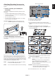
4. Installing and removing the optional table top stand 5. Prevent Tipping CAUTION: Installing and removing the stand must be done by four or more people. For installation, follow the instructions included with the stand or mounting equipment. Use only those devices recommended by the manufacturer. NOTE: When using the display with the optional table top stand, fasten the LCD to a wall using a cord or chain that can support the weight of the monitor in order to prevent the monitor from falling.
When mounting in an enclosed space or recessed area, leave adequate room between the monitor and the enclosure to allow heat to disperse, as shown below. 100 mm 100 mm 30 mm 100 mm 100 mm Must be under 40 Degree Celsius. Allow adequate ventilation or provide air conditioning around the monitor, so that heat can properly dissipate away from the unit and the mounting equipment; especially when you use monitors in a multiple screen configuration.
Parts Name and Functions Control Panel A Power Button ( H Menu/Exit Button (MENU/EXIT) ) Switches the power on/standby. See also page 20. Activates the OSD menu when the OSD menu is turned off. Acts as a back button within the OSD to move to the previous OSD menu. Acts as an EXIT button to close the OSD when on the main menu. B Mute Button (MUTE) Switches the audio mute on/off. C Input/Set Button (INPUT/SET) INPUT: Toggle switches between below inputs.
English Terminal Panel USB Upstream A AC IN Connector J USB Port Connects with the supplied power cord. Downstream port (USB Type-A). Connect USB devices. USB2: Upstream port (USB Type-B). Connect external equipment such as a computer. To control the monitor from connected external equipment, please use this port. USB CM1 (2A): Power supply port. USB CM2: Service port. Please do not connect devices. USB MP: USB storage device port. This port is for future software upgrades.
P Option Board Slot Slot 2 type accessory is available. Please contact your supplier for detailed information. NOTE: Please contact your supplier for available option board. Q Security Slot Security and theft protection lock compatible with Kensington security cables/equipment. For products, visit Kensington’s website, http://www.kensington.com/ R Rating Label S Intelligent Wireless Data Sensor Sensor for wireless communication of monitor for information and settings.
J UP/DOWN Button ( / ) button to move the highlighted area up or down Acts as to select adjustment items within the OSD menu. When using PIP (picture in picture), moves the small screen up or down. K MINUS/PLUS (-/+) Button Increases or decreases the adjustment level within the OSD menu settings. When using PIP (picture in picture), moves the small screen left or right. L SET/POINT ZOOM Button SET: When OSD is shown, this button acts as “set button” when you make a selection.
IMAGE FLIP Button Toggle switches between [H FLIP], [V FLIP], [180° ROTATE] and [NONE]. See page 35. ACTIVE PICTURE Button Selects active picture. MULTI PICTURE Button ON/OFF Button: Toggle switches between ON and OFF. MODE Button: Selects a mode from PIP (picture in picture) or PBP (picture by picture). CHANGE Button: Swaps images between two pictures. PICTURE ASPECT Button: Selects active picture frame aspect.
NEC recommends the following battery use: 1. Determine the installation location CAUTION: Installing your LCD monitor must be done by a qualified technician. Contact your supplier for more information. • Place “AAA” size batteries matching the (+) and (-) signs on each battery to the (+) and (-) signs of the battery compartment. • Do not mix battery brands. CAUTION: MOVING OR INSTALLING THE LCD MONITOR MUST BE DONE BY FOUR OR MORE PEOPLE.
5. Switch on the power of all the attached external equipment When connected with a computer, switch on the power of the computer first. 6. Operate the attached external equipment Show the signal on the screen from the desired input source. 7. Adjust the sound Make volume adjustments when required. 8. Adjust the image (See page 33) Make adjustments such as backlight or contrast when required. 9.
NOTE: Do not connect or disconnect cables when turning on the monitor’s main power or other external equipment’s power, as this may result in a loss of the monitor image. NOTE: Use an audio cable without a built-in resistor. Using an audio cable with a built-in resistor turns down the sound. Before making connections: * First turn off the power of all the attached equipment and make connections. * Refer to the user’s manual included with each separate piece of equipment.
Connecting a Personal Computer Connecting your computer to your LCD monitor will enable you to reproduce your computer’s video signal output. Some display cards may not be able to support the required resolution for proper image reproduction. Your LCD monitor shows proper image by adjusting the factory preset timing signal automatically.
USB1: USB downstream port (Type-A). Connect a USB compatible flash memory or keyboard to Down Stream Port. USB2: USB upstream port (Type-B). Connect to a USB compatible computer with a USB cable. A USB compatible computer connected to USB2 can control the devices connected to USB1. USB CM1 (2A): Power supply port. Please refer to the specifications page for power supply information (see pages 72, 73 and 74). USB CM2: Service port. Please do not connect devices. USB MP: USB downstream port (Type-A).
Basic Operation Power ON and OFF Modes The LCD monitor power indicator will turn blue while powered on. NOTE: The Main Power switch must be in the ON position in order to power up the monitor using the remote control or the Power button.
LED indicator status and lighting pattern Glowing blue Blinking green*1 Aspect English Power Indicator For MP Condition Recovery FULL Normal Under any of the conditions below, no input signal has been detected by the monitor during the period of time you set: • The monitor is using an option board. 1. Turn on the monitor • INPUT DETECT is set to a by the remote setting except for NONE. control or the • USB POWER is set to ON. monitor button. • DisplayPort in the TERMINAL MODE is set to MST. 2.
Media Player Plays saved data, such as still and motion images, BGM (Background Music), on a USB storage device or microSD memory card connected to the monitor. Top screen of the viewer • Select [SETTINGS] to change the media player settings.
English BGM Supported formats File extension Audio codec .wav LPCM .mp3 MP3 Information Item Conditions Resolution JPEG 5000x5000 PNG 4000x4000 MPEG1 480@30fps MPEG2 MP@ML, MP@HL, 1080p@30fps / 1080i@60fps H.264 High profile Lv.4.
Compatible USB memory Format a USB memory in the FAT32 format or FAT16 format for using it in the Media Player. Refer to the computer’s instruction user’s manual or Help file on how to format a USB memory. Please use a USB memory with this monitor in accordance with the drawing below. If the physical size of the USB device is larger than the supported sizes listed below, please use a USB extension cable. USB memory Extension cable Under 7.
• Select a folder that contains images or movies. • A slideshow can be displayed using “MANUAL” in which the images are switched by operating a button on the remote control, or “AUTO” in which the images are switched automatically at a set interval (PLAY MODE is “AUTO”). • The default factory setting is “MANUAL”. To perform “AUTO”, set the “PLAY MODE” to “AUTO”. • The images will be displayed in the order selected under “Sort” on the file display screen.
NETWORK & OTHER SETTINGS Below are the options for the Network settings and Shared Folder settings for the Media Player. To select the settings, press the remote control SET/POINT ZOOM button on the NETWORK & OTHER SETTINGS. NETWORK SETTINGS for MEDIA PLAYER Menu Function IP SETTING Set these settings. IP ADDRESS SUBNET MASK DEFAULT GATEWAY DNS DNS PRIMARY DNS SECONDARY NETWORK INFORMATION for the Media Player displays what you set in the NETWORK SETTINGS for the Media Player.
You can copy data to the microSD memory card, such as motion or still images, from a computer connected to the same network as the monitor. Please set the NETWORK SETTINGS for the Media Player (See page 26) first to copy data. NOTE: When the monitor is copying a folder, the LED indicator blinks in red. When the monitor is in this condition, do not eject a microSD memory card from the monitor and do not turn off the monitor’s main power.
4. RELOAD. Updates microSD memory card data. 5. THUMB/LIST. The files can be displayed using either icons or thumbnails. Displays description of the file or folder if you select thumb name or file name. 6. SORT. Select sort type. The folders saved in the microSD are sorted based on what you selected in sort type. 7. Connect to the other monitor’s SD-CARD VIEWER then open them.
Depending on the setting of SPECTRAVIEW ENGINE in the OSD PICTURE menu (see page 35), the selection choices for the Picture Mode are different. SPECTRAVIEW ENGINE is set to “ON”: Select from five different picture modes, either via the OSD menu item PICTURE MODE or using the PICTURE MODE button on the wireless remote control. Select the Picture Mode with the wireless remote control By pressing the Picture Mode button, the picture mode changes.
GAMMA Allows you to manually select the brightness level of grayscale. There are five selections: sRGB, L STAR, DICOM SIM. and CST. We recommend to show grayscale image data on screen. sRGB: GAMMA setting for sRGB. L STAR: GAMMA setting for the CIELAB color space Lab. DICOM SIM.: DICOM GSDF (Grayscale Standard Display Function) is typically used for medical imaging. CST: CUSTOM VALUE can be adjusted when CST is selected as the GAMMA SELECTION setting.
Select from five different picture modes, either via the OSD menu item PICTURE MODE or using the PICTURE MODE button on the wireless remote control. For DisplayPort1, DisplayPort2, OPTION*, HDMI1, HDMI2 STANDARD sRGB CINEMA CUSTOM1 CUSTOM2 For MP STANDARD CINEMA CUSTOM1 CUSTOM2 HIGHBRIGHT HIGHBRIGHT PRESET types PRESET PURPOSE HIGH BRIGHT Highest brightness setting. STANDARD Standard setting. sRGB The standard color space used for the Internet, Windows® operating systems and digital cameras.
OSD (On-Screen-Display) Controls NOTE: Some functions may not be available depending on the model or optional equipment. Input source Main Menu Icons Main Menu Item Sub Menu MULTI-INPUT PICTURE: PICTURE MODE BRIGHTNESS GAMMA COLOR CONTRAST SHARPNESS UHD UPSCALING ASPECT ADVANCED ROTATION SPECTRAVIEW ENGINE RESET Select OPTION PICTURE MODE SVE-1 SETTING PRESET PROGRAMMABLE1 LUMINANCE 100 % BLACK 5% GAMMA sRGB CUSTOM VALUE --WHITE 6500 K WHITE (x, y) x: 0.279 y: 0.292 RED (x, y) x: 0.683 y: 0.
English Setting INPUT DisplayPort1 Select input signal. DisplayPort2 HDMI1 HDMI2 HDMI3 MP Displays images or movies saved in microSD memory card or USB storage device. Please refer to the Media Player setting (See page 22). OPTION*3 Select input signal. PICTURE PICTURE MODE Select picture mode: SpectraView Engine = OFF: [HIGHBRIGHT], [STANDARD], [sRGB], [CINEMA], [CUSTOM1], [CUSTOM2].
ASPECT Select the aspect ratio of the screen image. NOTE: When the ASPECT is set to DYNAMIC, the image will be changed to FULL image before IMAGE FLIP, then start IMAGE FLIP. When the ASPECT is DYNAMIC or ZOOM, the image will be changed to FULL image before TILE MATRIX, and then start TILE MATRIX. After TILE MATRIX, the ASPECT will be returned to the previous ASPECT or set ASPECT during TILE MATRIX. If SCREEN SAVER is set, the ASPECT setting automatically changes to FULL from what you set.
IMAGE FLIP NONE H FLIP V FLIP 180° ROTATE OSD FLIP Shows the inverse image right-left, up-down or rotation. Press + or - to select. NOTE: This function is not available when MOTION in SCREEN SAVER is “ON”. NOTE: When the ASPECT is set to DYNAMIC, the image will be changed to FULL image before ROTATE starts. When selecting IMAGE FLIP (except for NONE), the following functions are disabled: MULTI PICTURE MODE, TEXT TICKER, STILL, POINT ZOOM and TILE MATRIX.
SCHEDULE SCHEDULE SETTINGS Creates a working schedule for the monitor. Press the , +, - buttons to navigate and change the schedule settings. Press the SET/ZOOM on the remote or Input change buttons on the monitor to select settings. NOTE: Please set DAY & TIME before configuring the SCHEDULE SETTINGS. When the SCHEDULE SETTINGS window is closed, any schedules that you set are saved. If schedules are set for the same time, higher SETTINGS numbers are given the priority.
Sets daylight savings on or off. NOTE: Please set the TIME & DATE setting first if you change the DAYLIGHT SAVING setting. DAYLIGHT SAVING If ON is selected, please set daylight savings settings below. BEGIN MONTH Set daylight savings beginning date. END MONTH Set daylight savings ending date. TIME DIFFERENCE Set the time difference. OFF TIMER Set the monitor to power off after a preset time period. A time period between 1 to 24 hours may be set. NOTE: SCHEDULE is not available if OFF TIMER is ON.
TEXT TICKER*1, *2 NOTE: When TEXT TICKER is set, MULTI PICTURE MODE and STILL are not available. TEXT TICKER is released if following menu is activated: MULTI PICTURE MODE, TILE MATRIX, SCREEN SAVER, IMAGE FLIP, SUPER in INPUT CHANGE. When this function is active, POINT ZOOM and STILL are not available. MODE Enables Text Ticker and allows you to set Horizontal or Vertical direction. POSITION Selects the location of the Text Ticker on the screen.
LANGUAGE Select the language used by the OSD. ENGLISH DEUTSCH FRANÇAIS ITALIANO ESPAÑOL SVENSKA РУССКИЙ OSD TIME Turns off the OSD after a period of inactivity. The preset choices are 10-240 seconds. OSD POSITION Determines the location where the OSD appears on the screen. UP DOWN RIGHT LEFT INFORMATION OSD COMMUNICATION INFO. Selects whether the Information OSD is displayed or not. The Information OSD will appear when the input signal or input source changes.
TILE MATRIX Allows one image to be expanded and displayed over multiple screens (up to 100) through a distribution amplifier. NOTE: Low resolution is not suitable for tiling to a large number of monitors. You can operate without a distribution amplifier at a lower number of screens. This function is released when selecting SCREEN SAVER or IMAGE FLIP except for NONE. Dynamic and Zoom will not work when Tile Matrix is activated.
POWER SAVE AUTO POWER SAVE TIME SETTING Set ENABLE or DISABLE. If you set it to ENABLE, set how long the monitor waits to go into power save mode after signal is lost. For more details please check the Power Indicator (See page 43). NOTE: The display card might not stop sending the digital data even though the image might have disappeared. If this occurs the monitor will not switch into power management mode. POWER SAVE is disabled when AUTO OFF or CUSTOM is selected in HUMAN SENSING*3.
CHANGE PASSWORD Allows the security password to be changed. The factory preset password is 0000. SECURITY PASSWORD Input security password. SECURE MODE OFF The security password is not required when the monitor power is on. START-UP LOCK The security password is required when the monitor power is on. CONTROL LOCK The security password is required when a remote control button or a control button on the monitor is pressed.
AUTO BRIGHTNESS DisplayPort1, DisplayPort2, MP, OPTION*3 inputs only ROOM LIGHT SENSING Adjusts the backlight of the LCD automatically depending on the amount of ambient light. Adjusts the brightness level according to the input signal. NOTE: Do not select this function when ROOM LIGHT SENSING is MODE1 or MODE2. The backlight of the LCD screen can be set to increase or decrease depending on the amount of ambient light within the room. If the room is bright, the monitor becomes correspondingly bright.
USB TOUCH POWER (Not available) EXTERNAL CONTROL When ON is set, the monitor can be controlled by a device connected to USB2 port. PC SOURCE Select a device connected to USB1 which controls the monitor. If a control device is specific, select EXTERNAL PC or OPTION. OPTION is only available when slot 2 type PC option is connected to the monitor. USB POWER Selects a power relation of USB CM1 (2A). Set ON to supply the power to the USB CM1 (2A).
Selects signal type according to the slot 2 type option specifications. AUTO Sets the signal type automatically. 1CH Fills the screen entirely with the signal which is selected in SLOT2 CH SELECT. 2CH The DisplayPort signal is displayed on the left half of the screen, the TMDS signal is displayed on the right half. If the internal PC does not support either one of the signal types, the existing signal will automatically be displayed on the full screen.
NOTE 1: CREATING A SCHEDULE The schedule function allows the monitor to be set to power on or to be on standby at different times. Up to seven different schedules can be programmed. To program the schedule: 1. Enter the SCHEDULE menu. Highlight SCHEDULE SETTINGS using the up and down buttons. Press the SET/POINT ZOOM or the + button to enter the Settings menu. Highlight the desired schedule number and press SET/POINT ZOOM. The box next to the number will turn yellow. The schedule can now be programmed. 2.
English Remote Control Functions REMOTE CONTROL ID FUNCTION Monitor ID:1 Monitor ID:2 Monitor ID:3 Remote works Remote works Remote works REMOTE CONTROL ID The remote control can be used to control up to 100 individual MultiSync monitors using what is called the REMOTE CONTROL ID mode. The REMOTE CONTROL ID mode works in conjunction with the Monitor ID, allowing control of up to 100 individual MultiSync monitors.
Multiple Monitors Connection You can control multiple monitors by using RS-232C, REMOTE IN or LAN daisy-chain connection. NOTE: Multiple monitors that are daisy-chained have a limit to the connectable monitors. Please execute AUTO ID (see page 40) before manually specifying the ID number or control by the specified ID number.
This LCD monitor can be controlled by connecting a personal computer with an RS-232C (reverse type) terminal. Functions that can be controlled by a personal computer are: • Power ON or standby. • Switching between input signals. • Sound Mute ON or OFF. Connection LCD Monitor + computer. • Please turn off the monitor’s main power when connecting a computer to the monitor. • Please turn on the connecting computer first then turn on the monitor’s main power.
1) Interface PROTOCOL BAUD RATE DATA LENGTH PARITY STOP BIT FLOW CONTROL RS-232C 9600 [bps] 8 [bits] NONE 1 [bit] NONE This LCD monitor uses RXD, TXD and GND lines for RS-232C control. The reverse type cable (null modem cable) (not included) should be used for RS-232C control. 2) PIN ASSIGNMENT RS-232C input/output Pin No 1 2 3 4 5 6 7 8 9 Name NC RXD TXD NC GND NC NC NC NC D-SUB 9P (Monitor side) 5 1 6 9 This LCD monitor uses RXD, TXD and GND lines for RS-232C control.
Connecting to a Network Using a LAN cable allows you to specify the Network Settings and the Alert Mail Settings by using an HTTP server function. To use a LAN connection you are required to assign an IP address. Example of LAN connection: Server NOTE: Use a category 5 or higher LAN cable. Hub LAN cable (not supplied) Network Setting by Using an HTTP Browser Overview Connecting the monitor to a network allows for monitor control from a computer via the network.
Preparation Before Use Connect the monitor to the network, using a commercially available LAN cable, before attempting to use browser operations. Operation with a browser that uses a proxy server may not be possible depending on the type of proxy server and the setting method. Although the type of proxy server will be a factor, it is possible that items that have been set will not be shown, depending on the effectiveness of the cache, and the contents set from the browser may not be reflected in operation.
English Network Setting Click on “NETWORK” on the left column below HOME. IP SETTING Select an option for setting the IP ADDRESS. AUTO: Automatically assign an IP address. MANUAL: Manually set an IP address for the monitor connected to the network. NOTE: Consult your network administrator if you have any trouble. IP ADDRESS Set your IP address for the monitor connected to the network when [MANUAL] is selected for [IP SETTING].
Mail Setting Click on “MAIL” on the left column below HOME. This option notifies your computer about an error message via e-mail when using wired LAN. An error message will be sent when an error occurs in the monitor. ALERT MAIL Selecting [ENABLE] will turn on the Alert Mail feature. Selecting [DISABLE] will turn off the Alert Mail feature. STATUS MESSAGE Selecting [ENABLE] will turn on the STATUS MESSAGE feature. Selecting [DISABLE] will turn off the STATUS MESSAGE feature.
Click on “SNMP” on the left column below HOME. The SNMP protocol is used to get status information and to control a monitor directly via the network. Version: SNMP v1 Authenticated plaintext by community name, does not return a confirmation message of the trap. SNMP v2c Authenticated plaintext by community name, returns a confirmation message of the trap. Community name: The default setting of community name is “public”. It is read only. You can set community names for up to 3 settings.
Name Settings Click on “NAME” on the left column below HOME. MONITOR NAME Defines a monitor name. The name must be max. 16 characters long. The default is the model name. HOST NAME (CONTROL) Type in the hostname of the monitor which is connected to the network. Up to 15 alphanumeric characters can be used. HOST NAME (MP) Type in the hostname of the network to be used in the Media Player connected to the monitor. Up to 15 alphanumeric characters can be used.
English Connecting interface RS-232C Interface PROTOCOL BAUD RATE DATA LENGTH PARITY STOP BIT FLOW CONTROL RS-232C 9600 [bps] 8 [bits] NONE 1 [bit] NONE LAN interface PROTOCOL PORT NUMBER COMMUNICATION SPEED TCP 7142 AUTO setting (10/100Mbps) Control command diagram For other commands, please see “External_Control.pdf” file on the CD-ROM supplied with the monitor.
Supporting HDMI CEC command OSD menu CEC (Consumer Electronics Control) HDMI CEC command name Explanation One Touch Play If HDMI CEC supporting devices are turned on, the monitor connected to the devices by HDMI cable is also turned on automatically. After that, the input switches to HDMI from an input, which you selected. If the monitor is turned on when HDMI CEC devices are turned on, it changes the input from the original one to HDMI.
English POINT ZOOM Using the “SET/POINT ZOOM” button on the remote control enlarges part of the screen image. Press the CH+/- button to zoom in or out. The image can be expanded up to 10 times. 1 Press the [SET/POINT ZOOM] button on the remote control. The icon looks like a magnifier. 2 Move the magnifier icon with the [ ] [ ] [+] [-] buttons. 3 Press the [CH+] to zoom in. Press [CH-] to zoom out. 4 Press the [SET/POINT ZOOM] to let the icon disappear.
PROOF OF PLAY This function allows to sending of messages for the current status of the monitor by self-diagnosis. Check item ① ② ③ ④ ⑤ ⑥ ⑦ Message INPUT DisplayPort1, DisplayPort2, HDMI1, HDMI2, HDMI3, OPTION*, MP Resolution ex.
This function allows getting the monitor status via wireless communication, even while the monitor’s main power is off or is not yet installed. Even some OSD items may be set by using this feature. NOTE: Sensor position: See page 10 and 11. Please contact your supplier for detailed information. Complied with ISO 15693.
PICTURE NUMBER: 3 PICTURES PIP/PBP1/PBP2 PICTURE 1: HDMI1 (MODE1) HDMI1 Connector Picture 1: HDMI1 (MODE1) Picture 2 Connector HDMI1 HDMI IN1 HDMI2 HDMI IN2 HDMI3 HDMI IN3 MP DisplayPort2 DisplayPort1 – DisplayPort IN2 DisplayPort IN1 Option board slot (SLOT2 (DP)) Option board slot (SLOT2 (DP+TMDS)) Option board slot (SLOT2 (TMDS)) OPTION HDMI IN1 HDMI2 HDMI3 HDMI IN2 HDMI IN3 MP – Picture 3 DisplayPort2 DisplayPort1 DisplayPort IN2 TERMINAL MODE MODE MODE MODE MODE MODE MODE SETTINGS*
PICTURE 1: HDMI3 (MODE1) Picture 1: HDMI3 (MODE1) Connector Picture 2 Connector HDMI1 HDMI IN1 HDMI2 HDMI IN2 HDMI3 HDMI IN3 MP DisplayPort2 DisplayPort1 – DisplayPort IN2 DisplayPort IN1 Option board slot (SLOT2 (DP)) Option board slot (SLOT2 (DP+TMDS)) Option board slot (SLOT2 (TMDS)) OPTION HDMI1 HDMI2 HDMI3 MP HDMI IN1 HDMI IN2 HDMI IN3 – TERMINAL MODE MODE MODE MODE MODE MODE MODE SETTINGS*1 1 2 1 2 1 2 1 MODE 1 Yes No No No Yes No No MODE 2 No No No No No No No MODE 1 No No Yes No
PIP/PBP1/PBP2 PICTURE 1: DisplayPort1 Picture 1: DisplayPort1 Connector Picture 2 Connector HDMI1 HDMI IN1 HDMI2 HDMI IN2 HDMI3 HDMI IN3 MP DisplayPort2 DisplayPort1 – DisplayPort IN2 DisplayPort IN1 Option board slot (SLOT2 (DP)) Option board slot (SLOT2 (DP+TMDS)) Option board slot (SLOT2 (TMDS)) OPTION HDMI1 HDMI2 HDMI3 MP HDMI IN1 HDMI IN2 HDMI IN3 – TERMINAL MODE MODE MODE MODE MODE MODE MODE SETTINGS*1 1 2 1 2 1 2 1 MODE 1 Yes No Yes No Yes No Yes MODE 2 No No No No No No No MODE
PICTURE 1: OPTION (TMDS) Picture 1: OPTION (TMDS) Connector Picture 2 Connector HDMI1 HDMI IN1 HDMI2 HDMI IN2 HDMI3 HDMI IN3 MP DisplayPort2 DisplayPort1 – DisplayPort IN2 DisplayPort IN1 Option board slot (SLOT2 (DP)) Option board slot (SLOT2 (DP+TMDS)) Option board slot (SLOT2 (TMDS)) OPTION HDMI1 HDMI2 HDMI3 MP HDMI IN1 HDMI IN2 HDMI IN3 – TERMINAL MODE MODE MODE MODE MODE MODE MODE SETTINGS*1 1 2 1 2 1 2 1 MODE 1 Yes No Yes No Yes No Yes MODE 2 No No No No No No No MODE 1 Yes No Yes
PBP3 PICTURE 1: HDMI2 (MODE1) Picture 1: HDMI2 (MODE1) Connector Picture 2 Connector HDMI1 HDMI IN1 HDMI2 HDMI IN2 HDMI3 HDMI IN3 MP DisplayPort2 DisplayPort1 – DisplayPort IN2 DisplayPort IN1 Option board slot (SLOT2 (DP)) Option board slot (SLOT2 (DP+TMDS)) Option board slot (SLOT2 (TMDS)) OPTION HDMI1 HDMI2 HDMI3 MP HDMI IN1 HDMI IN2 HDMI IN3 – TERMINAL MODE MODE MODE MODE MODE MODE MODE SETTINGS*1 1 2 1 2 1 2 1 MODE 1 Yes No Yes No No No No MODE 2 No No No No No No No MODE 1 Yes No
PICTURE 1: DisplayPort2 Picture 1: DisplayPort2 Connector Picture 2 Connector HDMI1 HDMI IN1 HDMI2 HDMI IN2 HDMI3 HDMI IN3 MP DisplayPort2 DisplayPort1 – DisplayPort IN2 DisplayPort IN1 Option board slot (SLOT2 (DP)) Option board slot (SLOT2 (DP+TMDS)) Option board slot (SLOT2 (TMDS)) OPTION HDMI1 HDMI2 HDMI3 MP HDMI IN1 HDMI IN2 HDMI IN3 – TERMINAL MODE MODE MODE MODE MODE MODE MODE SETTINGS*1 1 2 1 2 1 2 1 MODE 1 Yes No Yes No Yes No Yes MODE 2 No No No No No No No MODE 1 Yes No Yes N
PBP3 PICTURE 1: OPTION (TMDS) Picture 1: OPTION (TMDS) Connector Picture 2 Connector HDMI1 HDMI IN1 HDMI2 HDMI IN2 HDMI3 HDMI IN3 MP DisplayPort2 DisplayPort1 – DisplayPort IN2 DisplayPort IN1 Option board slot (SLOT2 (DP)) Option board slot (SLOT2 (DP+TMDS)) Option board slot (SLOT2 (TMDS)) OPTION HDMI1 HDMI2 HDMI3 MP HDMI IN1 HDMI IN2 HDMI IN3 – Picture 3 DisplayPort2 DisplayPort1 DisplayPort IN2 TERMINAL MODE MODE MODE MODE MODE MODE MODE SETTINGS*1 1 2 1 2 1 2 1 MODE 1 Yes No Yes
Reduced Footprint: Provides the ideal solution for environments with superior image quality. SPECTRAVIEW ENGINE: This system is designed for improvement the visual quality of the monitor. Each monitor is calibrated at the factory. By making automatic adjustments during operation of the monitor hardware in real time, optimal settings are configured without any user interaction. OmniColor: Combines Six-axis color control and the sRGB standard.
Troubleshooting No picture • The signal cable should be completely connected to the display card/computer. • The display card should be completely seated in its slot. • Check the main Power Switch, it should be in the ON position. • Power Switches for the monitor and computer should be in the ON position. • Make sure that a supported resolution has been selected on the display card or system being used.
Snowy Picture, Poor Sound in TV • Check antenna/cable connection. Use new cable if necessary. No Sound • Check to see if the audio cable is properly connected. The USB Hub does not operate • Check to make sure that the USB cable is properly connected. Refer to your USB device user’s manual. • Check to see if MUTE is activated. Use the remote control to enable or disable the Mute function. • • Check to see if VOLUME is set to a minimum.
Specifications - V754Q Product Specifications LCD Module Pixel Pitch: Resolution: Color: Brightness: Contrast Ratio: Viewing Angle: Frequency 75"/189.27 cm diagonal 0.430 mm 3840 x 2160 Over 1073 million colors (depending on display card used) 500 cd/m2 (Max.) @25°C 1200:1 89° (typ) @ CR>10 Horizontal: 31.5 kHz - 91.1 kHz Vertical: 24.0 - 85.0 Hz (Digital Input) Pixel Clock Digital: 25.0 MHz - 600.0 MHz (HDMI/DisplayPort) Viewable Size 1649.66 x 927.
English Specifications - V864Q Product Specifications LCD Module Pixel Pitch: Resolution: Color: Brightness: Contrast Ratio: Viewing Angle: Frequency 86"/217.43 cm diagonal 0.494 mm 3840 x 2160 Over 1073 million colors (depending on display card used) 500 cd/m2 (Max.) @25°C 1200:1 89° (typ) @ CR>10 Horizontal: 31.5 kHz - 91.1 kHz Vertical: 24.0 - 85.0 Hz (Digital Input) Pixel Clock Digital: 25.0 MHz - 600.0 MHz (HDMI/DisplayPort) Viewable Size 1895.04 x 1065.
Specifications - V984Q Product Specifications LCD Module Pixel Pitch: Resolution: Color: Brightness: Contrast Ratio: Viewing Angle: Frequency 98"/247.82 cm diagonal 0.562 mm 3840 x 2160 Over 1073 million colors (depending on display card used) 500 cd/m2 (Max.) @25°C 1300:1 89° (typ) @ CR>10 Horizontal: 31.5 kHz - 91.1 kHz Vertical: 24.0 - 85.0 Hz (Digital Input) Pixel Clock Digital: 25.0 MHz - 600.0 MHz (HDMI/DisplayPort) Viewable Size 2158.85 x 1214.
NEC DISPLAY SOLUTIONS is strongly committed to environmental protection and sees recycling as one of the company’s top priorities in trying to minimize the burden placed on the environment. We are engaged in developing environmentally-friendly products, and always strive to help define and comply with the latest independent standards from agencies such as ISO (International Organisation for Standardization) and TCO (Swedish Trades Union).
WEEE Mark (European Directive 2012/19/EU and amendments) Disposing of your used product: In the European Union EU-wide legislation as implemented in each Member State requires that used electrical and electronic products carrying the mark (left) must be disposed of separately from normal household waste. This includes monitors and electrical accessories, such as signal cables or power cords.
1. MPEG-4 AVC THIS PRODUCT IS LICENSED UNDER THE AVC PATENT PORTFOLIO LICENSE FOR THE PERSONAL USE OF A CONSUMER OR OTHER USES IN WHICH IT DOES NOT RECEIVE REMUNERATION TO (i) ENCODE VIDEO IN COMPLIANCE WITH THE AVC STANDARD (“AVC VIDEO”) AND/OR (ii) DECODE AVC VIDEO THAT WAS ENCODED BY A CONSUMER ENGAGED IN A PERSONAL ACTIVITY AND/OR WAS OBTAINED FROM A VIDEO PROVIDER LICENSED TO PROVIDE AVC VIDEO. NO LICENSE IS GRANTED OR SHALL BE IMPLIED FOR ANY OTHER USE.