
Server Technical Overview

I/O Subsystem
2-8
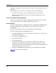
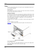
Indicators on the Memory Board
The memory board contains a green LED to indicate that the board is in service and an
amber LED to indicate that the board needs attention. Do not remove a memory board
while the green LED is lit.
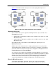
Dynamic DIMM Sparing
Dynamic DIMM sparing automatically substitutes a spare DIMM in place of an
operational DIMM before a high rate of correctable errors leads to an uncorrectable error
and loss of data. The cell maintains normal memory operations during the dynamic
DIMM sparing process.
In dynamic DIMM sparing, a DIMM, in the last populated slot and next to the last
operational DIMM on the channel, must first have been reserved as a spare. Both
channels must be populated with identical spare DIMMs in the equivalent slot positions
on each channel.
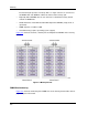
Memory Mirroring
Mirroring is an optional memory addressing mode that provides protection against
uncorrectable errors by maintaining two images of memory. With mirroring, all
uncorrectable errors, including a complete DIMM or channel failure, will not stop the
system.
Mirroring is between the two memory boards within the cell. (Mirroring between memory
boards in different cells is not supported.) On detection of a memory failure, the system
breaks the mirror and continues operation out of the remaining "good" memory board.
Once the mirror has been broken, you can remove the memory board with the failed
DIMM, replace the DIMM, reinstall the memory board, and reestablish mirroring.
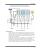
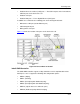
I/O Subsystem
The I/O subsystem consists of the I/O riser board, PCIe cards, and the PCIe card
carrier.
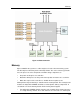
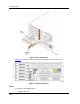
I/O Riser Board
The I/O riser board contains the following components:
y Three PCIe-to-PCIe x8 switches with each switch supporting two PCIe card slots
y Six PCIe slots which support the following features:
- Two full-length cards slots (slots 1 and 4) and four half-length card slots
- Full-height cards
- 25 watts per slot
- PCI Express Gen 1 (2.5 Gbps)
- Hot-plug capability