Software Manual 05.00 Technical Support Web Site: http://ws1.necii.
This manual has been developed by NEC Unified Solutions, Inc. It is intended for the use of its customers and service personnel, and should be read in its entirety before attempting to install or program the system. Any comments or suggestions for improving this manual would be appreciated. Forward your remarks to: NEC Unified Solutions, Inc. 4 Forest Parkway Shelton, CT 06484 necunifiedsolutions.
Table of Contents Features . . . . . . . . . . . . . . . . . . . . . . . . . . . . . . . . . . . . . . . . . . . . . . . . . . . . . . 1 About This Manual . . . . . . . . . . . . . . . . . . . . . . . . . . . . . . . . . . . . . . . . . . . . . . . . 3 Charts and Illustrations . . . . . . . . . . . . . . . . . . . . . . . . . . . . . . . . . . . . . . . . . . . . . 5 Abbreviated Dialing . . . . . . . . . . . . . . . . . . . . . . . . . . . . . . . . . . . . . . . . . . . . . . . 73 Account Codes . . . . . .
Table of Contents Direct Inward Dialing (DID) . . . . . . . . . . . . . . . . . . . . . . . . . . . . . . . . . . . . . . . 279 Direct Inward Line (DIL) . . . . . . . . . . . . . . . . . . . . . . . . . . . . . . . . . . . . . . . . . . 289 Direct Inward System Access (DISA) . . . . . . . . . . . . . . . . . . . . . . . . . . . . . . . . 293 Direct Station Selection (DSS) Console . . . . . . . . . . . . . . . . . . . . . . . . . . . . . . 305 Directed Call Pickup . . . . . . . . . . . . . . . . . . . . . .
Table of Contents Name Storing . . . . . . . . . . . . . . . . . . . . . . . . . . . . . . . . . . . . . . . . . . . . . . . . . . . 432 Networking . . . . . . . . . . . . . . . . . . . . . . . . . . . . . . . . . . . . . . . . . . . . . . . . . . . . 436 Night Service . . . . . . . . . . . . . . . . . . . . . . . . . . . . . . . . . . . . . . . . . . . . . . . . . . . 443 Off Hook Signaling . . . . . . . . . . . . . . . . . . . . . . . . . . . . . . . . . . . . . . . . . . . . . . 448 One-Touch Calling . .
Table of Contents Traffic Reports . . . . . . . . . . . . . . . . . . . . . . . . . . . . . . . . . . . . . . . . . . . . . . . . . . 585 Transfer . . . . . . . . . . . . . . . . . . . . . . . . . . . . . . . . . . . . . . . . . . . . . . . . . . . . . . . 587 Trunk Group Routing . . . . . . . . . . . . . . . . . . . . . . . . . . . . . . . . . . . . . . . . . . . . . 595 Trunk Groups . . . . . . . . . . . . . . . . . . . . . . . . . . . . . . . . . . . . . . . . . . . . . . . . . . .
Table of Contents 10-25 : H.323 Gateway Prefix Setup . . . . . . . . . . . . . . . . . . . . . . . . . . . . . . . . . 774 10-26 : IP System Operation Setup . . . . . . . . . . . . . . . . . . . . . . . . . . . . . . . . . . 775 10-27 : IP System ID . . . . . . . . . . . . . . . . . . . . . . . . . . . . . . . . . . . . . . . . . . . . . 777 10-28 : SIP Trunk Basic Setup . . . . . . . . . . . . . . . . . . . . . . . . . . . . . . . . . . . . . . 779 10-29 : SIP Proxy Setup . . . . . . . . . . . . . . . . .
Table of Contents Program 13 : Abbreviated Dialing . . . . . . . . . . . . . . . . . . . . . . . . . . . . . . . . . . . . . 855 13-01 : Abbreviated Dialing Function Setup . . . . . . . . . . . . . . . . . . . . . . . . . . . 855 13-02 : Group Abbreviated Dialing Bins . . . . . . . . . . . . . . . . . . . . . . . . . . . . . . 857 13-03 : Abbreviated Dialing Group Assignment for Extensions . . . . . . . . . . . . 859 13-04 : Abbreviated Dialing Number and Name . . . . . . . . . . . . . . . . . . . . . . . .
Table of Contents Program 16 : Department Group Setup . . . . . . . . . . . . . . . . . . . . . . . . . . . . . . . . . 947 16-01 : Department Group Basic Data Setup . . . . . . . . . . . . . . . . . . . . . . . . . . 947 16-02 : Department Group Assignment for Extensions . . . . . . . . . . . . . . . . . . . 950 16-03 : Secondary Department Group . . . . . . . . . . . . . . . . . . . . . . . . . . . . . . . . 952 Program 20 : System Option Setup . . . . . . . . . . . . . . . . . . . . . . . . . . . . . . .
Table of Contents 21-11 : Extension Ringdown (Hotline) Assignment . . . . . . . . . . . . . . . . . . . . 1034 21-12 : ISDN Calling Party Number Setup for Trunks . . . . . . . . . . . . . . . . . . 1036 21-13 : ISDN Calling Party Number Setup for Extensions . . . . . . . . . . . . . . . 1038 21-14 : Walking Toll Restriction Password Setup . . . . . . . . . . . . . . . . . . . . . . 1040 21-15 : Individual Trunk Group Routing for Extensions . . . . . . . . . . . . . . . . .
Table of Contents Program 24 : Hold/Transfer Setup . . . . . . . . . . . . . . . . . . . . . . . . . . . . . . . . . . . . 1099 24-01 : System Options for Hold . . . . . . . . . . . . . . . . . . . . . . . . . . . . . . . . . . . 1099 24-02 : System Options for Transfer . . . . . . . . . . . . . . . . . . . . . . . . . . . . . . . . 1101 24-03 : Park Group . . . . . . . . . . . . . . . . . . . . . . . . . . . . . . . . . . . . . . . . . . . . . . 1104 24-04 : Automatic Trunk-to-Trunk Transfer Target Setup .
Table of Contents Program 31 : Paging Setup . . . . . . . . . . . . . . . . . . . . . . . . . . . . . . . . . . . . . . . . . 1171 31-01 : System Options for Internal/External Paging . . . . . . . . . . . . . . . . . . . 1171 31-02 : Internal Paging Group Assignment . . . . . . . . . . . . . . . . . . . . . . . . . . . 1173 31-03 : Internal Paging Group Settings . . . . . . . . . . . . . . . . . . . . . . . . . . . . . . 1175 31-04 : External Paging Zone Group . . . . . . . . . . . . . . . . . . . . . . . .
Table of Contents 40-06 : Voice Mail Automated Attendant Data Setup . . . . . . . . . . . . . . . . . . . 1243 40-07 : Voice Prompt Language Assignment for VRS . . . . . . . . . . . . . . . . . . 1245 40-08 : Voice Prompt Language Assignment for Mailboxes . . . . . . . . . . . . . 1247 40-09 : Voice Mail Multiple Address Group Setup . . . . . . . . . . . . . . . . . . . . . 1249 40-10 : Voice Announcement Service Option . . . . . . . . . . . . . . . . . . . . . . . . .
Table of Contents Program 44 : ARS/F-Route Setup . . . . . . . . . . . . . . . . . . . . . . . . . . . . . . . . . . . . 1303 44-01 : System Options for ARS/F-Route . . . . . . . . . . . . . . . . . . . . . . . . . . . . 1303 44-02 : Dial Analysis Table for ARS/F-Route Access . . . . . . . . . . . . . . . . . . 1304 44-03 : Dial Analysis Extension Table . . . . . . . . . . . . . . . . . . . . . . . . . . . . . . 1307 44-04 : ARS/F-Route Selection for Time Schedule . . . . . . . . . . . . . . . . . . . .
Table of Contents Program 81 : Basic Hardware Setup for Trunk . . . . . . . . . . . . . . . . . . . . . . . . . . 1397 81-01 : COIU Initial Data Setup . . . . . . . . . . . . . . . . . . . . . . . . . . . . . . . . . . . 1397 81-02 : DIOPU Initial Data Setup . . . . . . . . . . . . . . . . . . . . . . . . . . . . . . . . . . 1400 81-03 : 4TLIU Initial Data Setup . . . . . . . . . . . . . . . . . . . . . . . . . . . . . . . . . . . 1402 81-04 : ISDN BRI Layer 1 (T-Point) Initial Data Setup . . . . . . . . .
Table of Contents 84-16 : VOIPU Limiter Control Gain Setup . . . . . . . . . . . . . . . . . . . . . . . . . . 1478 84-17 : VOIPU Echo Canceller Control Setup . . . . . . . . . . . . . . . . . . . . . . . . 1480 84-18 : VOIPU Echo Canceller Control Setup . . . . . . . . . . . . . . . . . . . . . . . . 1482 84-19 : SIP Extension CODEC Information Basic Setup . . . . . . . . . . . . . . . . 1484 84-20 : SIP Extension Basic Information Setup . . . . . . . . . . . . . . . . . . . . . . .
Table of Contents Program 91 : Aspire Wireless Subscription . . . . . . . . . . . . . . . . . . . . . . . . . . . . . 1547 91-06 : Aspire Wireless Subscription, New . . . . . . . . . . . . . . . . . . . . . . . . . . . 1547 91-07 : Aspire Wireless Subscription, Delete . . . . . . . . . . . . . . . . . . . . . . . . . 1549 Program 92 : Copy Program . . . . . . . . . . . . . . . . . . . . . . . . . . . . . . . . . . . . . . . . 1551 92-01 : Copy by Extension Number . . . . . . . . . . . . . . . . . . . . . .
Table of Contents Table of Contents - 16 ◆ Aspire Software Manual
Features Aspire Software Manual Features ◆ 1
2 ◆ Features Aspire Software Manual
About This Manual About This Manual Section 1 - Features Before Reading This Section This section provides detailed information on the system’s features. If you don’t know what the various features are, review the Table of Contents for this section and the manual’s Index. After reviewing, turn back to this section for the specifics. Using This Section The features in this section are in alphabetical order, like a dictionary.
About This Manual Port Assignments: How the System Assigns Ports to the PCBs Port Calculation for Trunks: With the 4COIU-LS1, 8 COIU-LS1, 4COIU-LG1, 8COIU-LG1, 4DIOPU-A1, 8DIOPU-A1, 2BRIU, 4BRIU, and 8BRIU PCBs, the system detects the type of PCB (trunk or extension) and assigns the required extension or trunk ports to the slot. The system will use the next available port numbers - it will not reserve any ports. The T1/PRI PCB assigns the first 24 consecutive trunk ports.
Charts and Illustrations Charts and Illustrations Table 1: Abbreviated and Post Dialing Service Codes Abbreviated Service Codes1 Code Starting with an asterisk (*) Starting with a pound sign (#) For this feature. . . When you are. . . For this feature. . . When you are. . . * (+ ext. no.
Charts and Illustrations Table 2: Abbreviated and Post Dialing Service Codes Single Digit Post Dialing Codes For this feature. . . 1 Handsfree Answerback / Forced intercom Ringing Changing the signaling mode of your outgoing Intercom call 2 Call Waiting / Camp On / Callback / Trunk Queuing Camping on to or leaving a Callback at a busy extension or trunk 3-5 6 ◆ When you are. . .
Charts and Illustrations Table 3: Service Codes by Number Dial this Service Code. . .1 1 When you are. . . For this feature. . . Also see Function Key. . . Except where indicated, dial Service Code from Intercom dial tone (e.g., press idle CALL key first).
Charts and Illustrations Table 3: Service Codes by Number Dial this Service Code. . .1 1 *6 + Orbit (01-64) Also see Function Key. . .
Charts and Illustrations Table 3: Service Codes by Number Dial this Service Code. . .1 1 When you are. . . For this feature. . . Also see Function Key. . . Except where indicated, dial Service Code from Intercom dial tone (e.g., press idle CALL key first).
Charts and Illustrations Table 3: Service Codes by Number Dial this Service Code. . .1 1 ◆ For this feature. . . Also see Function Key. . . Except where indicated, dial Service Code from Intercom dial tone (e.g., press idle CALL key first).
Charts and Illustrations Table 3: Service Codes by Number Dial this Service Code. . .1 1 When you are. . . For this feature. . . Also see Function Key. . . Except where indicated, dial Service Code from Intercom dial tone (e.g., press idle CALL key first).
Charts and Illustrations Table 3: Service Codes by Number Dial this Service Code. . .1 1 Also see Function Key. . .
Charts and Illustrations Table 3: Service Codes by Number Dial this Service Code. . .1 1 When you are. . . For this feature. . . Also see Function Key. . . Except where indicated, dial Service Code from Intercom dial tone (e.g., press idle CALL key first).
Charts and Illustrations Table 3: Service Codes by Number Dial this Service Code. . .
Charts and Illustrations Table 4: Service Codes by Feature For this feature... 1 Except Dial this Service Code...1 When you are... Also see Function Key... where indicated, dial Service code form Intercom dial tone (e.g., press idle CALL key first).
Charts and Illustrations Table 4: Service Codes by Feature For this feature... 1 Except Also see Function Key... When you are... where indicated, dial Service code form Intercom dial tone (e.g., press idle CALL key first).
Charts and Illustrations Table 4: Service Codes by Feature For this feature... 1 Except Dial this Service Code...1 When you are... Also see Function Key... where indicated, dial Service code form Intercom dial tone (e.g., press idle CALL key first).
Charts and Illustrations Table 4: Service Codes by Feature For this feature... 1 Except Dial this Service Code...1 where indicated, dial Service code form Intercom dial tone (e.g., press idle CALL key first).
Charts and Illustrations Table 4: Service Codes by Feature For this feature... 1 Except Dial this Service Code...1 When you are... Also see Function Key... where indicated, dial Service code form Intercom dial tone (e.g., press idle CALL key first). Voice Mail (Cont’d) *8 Calling your mailbox 154 Enabling Conversation Record at SLT set - Voice Over 6 (Off-hook) or 890 Sending a Voice Over to a busy extension after hearing Busy/Ring tone 48 Voice Response System (VRS) ** + ringing ext.
Charts and Illustrations Table 5: Function Key Codes by Features To program a key, press CALL, dial 851 (for 2-digit codes) or 852 (for 3-digit codes), press the key and enter the code (e.g., 48 for Voice Over). 26 For this feature... Use this key... When your are...
Charts and Illustrations Table 5: Function Key Codes by Features To program a key, press CALL, dial 851 (for 2-digit codes) or 852 (for 3-digit codes), press the key and enter the code (e.g., 48 for Voice Over). For this feature... Use this key... When your are... Key Lamp Status Also See Srvc Code Automatic Call Distribution (ACD) (cont.) Code: *16 Operation: Press key to put agent on hold. Press key again + 1 to hang up agent or 0 to bring agent back into call.
Charts and Illustrations Table 5: Function Key Codes by Features To program a key, press CALL, dial 851 (for 2-digit codes) or 852 (for 3-digit codes), press the key and enter the code (e.g., 48 for Voice Over). 28 Key Lamp Status Also See Srvc Code Externally Call Forwarding Door Box calls Slowly flashes red *4 Code: 15 Operation: Press key + Dest.
Charts and Illustrations Table 5: Function Key Codes by Features To program a key, press CALL, dial 851 (for 2-digit codes) or 852 (for 3-digit codes), press the key and enter the code (e.g., 48 for Voice Over).
Charts and Illustrations Table 5: Function Key Codes by Features To program a key, press CALL, dial 851 (for 2-digit codes) or 852 (for 3-digit codes), press the key and enter the code (e.g., 48 for Voice Over). 30 For this feature... Use this key... When your are...
Charts and Illustrations Table 5: Function Key Codes by Features To program a key, press CALL, dial 851 (for 2-digit codes) or 852 (for 3-digit codes), press the key and enter the code (e.g., 48 for Voice Over). For this feature... Use this key... When your are...
Charts and Illustrations Table 5: Function Key Codes by Features To program a key, press CALL, dial 851 (for 2-digit codes) or 852 (for 3-digit codes), press the key and enter the code (e.g., 48 for Voice Over). 32 For this feature... Use this key... When your are...
Charts and Illustrations Table 5: Function Key Codes by Features To program a key, press CALL, dial 851 (for 2-digit codes) or 852 (for 3-digit codes), press the key and enter the code (e.g., 48 for Voice Over). For this feature... Use this key... Voice Over Code: 48 Operation: Hear OffHook Signaling tone + Press key Aspire Software Manual When your are...
Charts and Illustrations Table 6: Function Key Codes by Number To program a key, press CALL, dial 851 (for 2-digit codes) or 852 (for 3-digit codes), press the key and enter the code (e.g., 48 for Voice Over). 34 Also see Srvc Code Use this key... For this feature... When you are... Key Lamp Status Code: 01 + dest. ext.
Charts and Illustrations Table 6: Function Key Codes by Number To program a key, press CALL, dial 851 (for 2-digit codes) or 852 (for 3-digit codes), press the key and enter the code (e.g., 48 for Voice Over). Use this key... For this feature... When you are... Key Lamp Status Also see Srvc Code Code: 12 Operation: Press key + Dest. Ext. Call Forwarding, No Answer Call Forwarding to extension or Voice Mail Slowly flashes red *2 + 6 Code: 13 Operation: Press key + Dest. Ext.
Charts and Illustrations Table 6: Function Key Codes by Number To program a key, press CALL, dial 851 (for 2-digit codes) or 852 (for 3-digit codes), press the key and enter the code (e.g., 48 for Voice Over). Use this key... For this feature... When you are...
Charts and Illustrations Table 6: Function Key Codes by Number To program a key, press CALL, dial 851 (for 2-digit codes) or 852 (for 3-digit codes), press the key and enter the code (e.g., 48 for Voice Over). For this feature... Code: 33 Operation: Call ext.
Charts and Illustrations Table 6: Function Key Codes by Number To program a key, press CALL, dial 851 (for 2-digit codes) or 852 (for 3-digit codes), press the key and enter the code (e.g., 48 for Voice Over). Use this key... For this feature... When you are...
Charts and Illustrations Table 6: Function Key Codes by Number To program a key, press CALL, dial 851 (for 2-digit codes) or 852 (for 3-digit codes), press the key and enter the code (e.g., 48 for Voice Over). Use this key... For this feature... Code: 68 + 0-2 Operation: Press key Voice Mail Code: 77 + extension or Message Center number Operation: Press key Code: 78 + Conversation Record Operation: Press key When you are...
Charts and Illustrations Table 6: Function Key Codes by Number To program a key, press CALL, dial 851 (for 2-digit codes) or 852 (for 3-digit codes), press the key and enter the code (e.g., 48 for Voice Over). 40 Also see Srvc Code Use this key... For this feature... When you are...
Charts and Illustrations Table 6: Function Key Codes by Number To program a key, press CALL, dial 851 (for 2-digit codes) or 852 (for 3-digit codes), press the key and enter the code (e.g., 48 for Voice Over). Also see Srvc Code Use this key... For this feature... When you are... Key Lamp Status Code: *16 Operation: Press key to put agent on hold. Press key again + 1 to hang up agent or 0 to bring agent back into call. Automatic Call Distribution (ACD) (cont.
Charts and Illustrations Table 7: System Number Plan/Capacities System Type: Aspire S Aspire M/L Aspire XL Analog Caller ID Detector 24 64 64 Classes of Service 15 15 15 Day/Night Mode Numbers 4 8 8 Day/Night Service Patterns 4 32 32 Dial Tone Detector DTMF Receiver 16 64 64 System System Ports • (trunks and analog/digital extensions) • Software thru 2.21 = 8 trunks and 26 extensions Software 2.
Charts and Illustrations Table 7: System Number Plan/Capacities System Type: Aspire S Aspire M/L Aspire XL 01-02 LD Trunk: 0-8 OPX: 0-8 01-08 LD Trunk: 0-200 OPX: 0-25 01-08 LD Trunk: 0-200 OPX: 0-25 PRIU Logical Ports N/A T-Bus: 1-200 S-Bus: 1-256 T-Bus: 1-200 S-Bus: 1-256 TLIU: • Physical Ports • Logical Ports N/A 01-08 0-200 01-08 0-200 VOIPU: • Physical Ports • Logical Ports 1-8 0-8 01-32 0-200 01-32 0-200 DID Translation Tables 20 20 20 DID Translation Table Entries 2000 2000
Charts and Illustrations Table 7: System Number Plan/Capacities System Type: Aspire S Aspire M/L Aspire XL 1-50 3 (1-24) (1-18) 1-256 (1-256) 2 (1-256) 2 1-384 (1-384) (1-384) (1-16) 2, 4 N/A (1-512) 5 002-512 (manual select) 5 257-512 (auto select) 5 (1-512) 5 002-512 (manual select) 5 385-512 (auto select) 5 Extension Telephone Extension Port Numbers • Keysets • Single Line Phones/Analog Devices • VoIP Extensions • Aspire Wireless 2 3 4 5 ESIU • Physical Ports • Logical Ports -Tone Ringer (2P
Charts and Illustrations Table 7: System Number Plan/Capacities System Type: Aspire S Aspire M/L Aspire XL 2PGDAD Modules 10 56 56 ADA (Recording Jack) Adapters 24 192 192 Aspire Wireless Bases N/A 12 12 Aspire Wireless Phones N/A 120 120 4 8 8 Door Box Numbers 1-4 1-8 1-8 DSS Consoles Numbers • 24-Button DLS Consoles, Maximum Installed • 110-Button DSS Consoles, Maximum Installed 8 24 8 256 8 384 4 32 32 Handsfree Adapter (HF-R) 24 192 192 Operator Access Number 0 0
Charts and Illustrations Table 7: System Number Plan/Capacities System Type: Aspire S Aspire M/L Aspire XL 193-256 With software 4.xx or higher: 193-512 193-256 With software 4.xx or higher: 193-512 193-512 APA Adapters 24 192 192 APR Adapters B1 = 24 B2 = 8 prior to 2.50 or 16 with 2.
Charts and Illustrations Table 7: System Number Plan/Capacities System Type: Aspire S Aspire M/L Aspire XL 8 (fixed extension ports 43-50) N/A N/A 72 6 72 72 Voice Mail Ports for IntraMail Ports for External Voice Mail 6 Though this is the maximum available in the NVM-Series voice mail, as each voice mail port requires an analog port, the total number is restricted by the Aspire S system to a maximum of 16.
Charts and Illustrations Table 7: System Number Plan/Capacities System Type: Aspire S Aspire M/L Aspire XL 0000 0000 0000 Level 1 (MF) PCPro/WebPro User Name: 374772 NEC-I 374772 NEC-I 374772 NEC-I Level 2 (IN) PCPro/WebPro User Name: 12345678 ASPIRE 12345678 ASPIRE 12345678 ASPIRE Level 3 (SA) PCPro/WebPro User Name: 0000 ADMIN1 0000 ADMIN1 0000 ADMIN1 Level 4 (SB) PCPro/WebPro User Name: 9999 ADMIN2 9999 ADMIN2 9999 ADMIN2 8 8 8 Passwords User Password for setting Toll Restrictio
Charts and Illustrations Table 8: System Tones Tone Repetitions Frequency Level Internal, Special and External Dial Tone Continuous 350 Hz + 440 Hz -16 dB Internal Recall Dial Tone 3 350 Hz + 440 Hz -16 dB Internal Busy Tone 1 Continuous 440 Hz + 480 Hz -16 dB DND Busy Tone Continuous 400 Hz -13 dB Internal Reorder Tone Continuous 480 Hz + 620 Hz -21 dB Internal Intercept Tone Continuous 350 Hz + 440 Hz -16 dB Internal Confirmation Tone 3 350 Hz + 440 Hz -16 dB Internal Hold
Charts and Illustrations Table 8: System Tones 50 ◆ Features Tone Repetitions Frequency Level External Busy Tone Continuous 400 Hz -13 dB External Special Audible Ring Tone, Voice Mail Message Waiting, Stutter Dial Tone for SLT Continuous 520 Hz -13 dB Trunk Ring Tone Range 1 (Selected in Program 22-03-01 for trunks and 15-02-02 for extensions) Combination of...
Charts and Illustrations Table 9: Multibutton Telephone Displays With this feature... You’ll see this display... (Idle telephone) Ext Date, Day and Time (ext name) CHECK SET ABB:COMMON You dial Service Code 854 to store a Group Abbreviated Dialing number. ABB (bin) (digits) Time and Date ABB You are storing Abbreviated Dialing numbers, where (bin) is the bin number and (digits) is the current stored number (if any). You press CALL and DIAL to dial a Common Abbreviated Dialing number.
Charts and Illustrations Table 9: Multibutton Telephone Displays With this feature... Alarm You’ll see this display... SET n ALARM DIAL TIME You dial 827 to set an alarm, the dial 1 (to set Alarm 1) or 2 (to set Alarm 2). Date, Day and Time EXT ALARM n SET n ALARM TIME SET n ALARM CANCEL SET ALARM 1:ALARM1 2:ALARM2 ALARM n Background Music Barge In ◆ Features You set an alarm time but do not hang up. You dial 827, 1 or 2 to select an alarm type then 9999 to cancel. You dial 827 to set an alarm.
Charts and Illustrations Table 9: Multibutton Telephone Displays With this feature... Call Forwarding (cont.) You’ll see this display... FWD Busy/no answer Extension No? You lift the handset and dial *22 for Call Forwarding when Busy. FWD Immediate Extension No? You lift the handset and dial *24 for Call Forwarding Immediate. FWD No answer Extension No? You lift the handset and dial *26 for Call Forwarding when Unanswered.
Charts and Illustrations Table 9: Multibutton Telephone Displays With this feature... Call Waiting/Camp On and Callback You’ll see this display... Date, Day and Time CAMP CANCEL You have dialed 870 to cancel a Camp-On or Call Waiting request. Callback Date, Day and Time CALL-BACK (ext name) Extension at which you left a Callback (shown in the name field) is calling you back.
Charts and Illustrations Table 9: Multibutton Telephone Displays With this feature... Dial Number Preview You’ll see this display... PREVIEW DIAL DIAL (digits) Dial Pad Confirmation Tone Direct Station Selection (DSS) Console Do Not Disturb You dial Service Code 824 to enable Dial Pad Confirmation Tone. Date, Day and Time CANCEL KEY TOUCH TN You dial Service Code 824 to cancel Dial Pad Confirmation Tone. Date, Day and Time You press ALT to activate Alternate Answering.
Charts and Illustrations Table 9: Multibutton Telephone Displays With this feature... Hold You’ll see this display... Date, Day and Time HOLD (ext name) You place an Intercom call on Hold, where (ext name) is the name of extension you placed on Hold. Date, Day and Time GROUP HOLD (ext name) You dial Service Code 832 to place an Intercom call on Group Hold, where (ext name) is the name of your Intercom caller. (Trk name) GROUP HOLD You dial Service Code 832 to place your trunk call on Group Hold.
Charts and Illustrations Table 9: Multibutton Telephone Displays With this feature... Message Waiting You’ll see this display... When... Date, Day and Time MSG >>> (ext name) You dialed Service Code *0 and left a message at the extension shown in (ext name). Date, Day and Time CANCEL MESSAGE You dialed 871 to cancel a message you left at another extension, continue by entering the extension number to be cancelled.
Charts and Illustrations Table 9: Multibutton Telephone Displays With this feature... Programmable Function Keys You’ll see this display... KEY PROGRAM KEY (nn) (function) For this key function . . . 58 ◆ Features When... You press a function key after dialing Service Code 851, where (function) is the currently programmed function, as follows: You see this display . . .
Charts and Illustrations Table 9: Multibutton Telephone Displays With this feature... You’ll see this display... When...
Charts and Illustrations Table 9: Multibutton Telephone Displays With this feature... You’ll see this display... When... Programmable Function Keys (cont) 63 SEND NO. NON NOTICE 64 ------------ 66 CTI TELECOM 67 MAIL BOX nnn 68 VM PLAY BACK SKIP, VM PLAY BACK SKIP, or AUTO ATTENDANT MONITOR 69 CONVERSATION RECORD 70 ANSWERING MACHINE 71 ANSWERING MESSAGE 77 VOICE MAIL MSG nnn 78 CONVERSATION RECORD 79 AUTO ATT.
Charts and Illustrations Table 9: Multibutton Telephone Displays With this feature... Programmable Function Keys (cont) You’ll see this display... KEY PROGRAM You dial Service Code 851 or 852 to program your function keys. KEY PROGRAM KEY (nn) (function You press a function key after dialing Service Code 851 or 852, where (function) is the currently programmed function.
Charts and Illustrations Table 9: Multibutton Telephone Displays With this feature... Selectable Ring Tones Serial Call Transfer Trunk Queuing You’ll see this display... SET INCOM RING 1:INT 2:EXT You dial Service Code 820 to set Selectable Ring Tones. SET INT INCOM RING INCOM RING1-8:? You dial Service Code 820 plus 1 to set Intercom Selectable Ring Tones. SET EXT INCOM RING INCOM RING1-8:? You dial Service Code 820 plus 2 to set trunk Selectable Ring Tones.
Charts and Illustrations Table 9: Multibutton Telephone Displays With this feature... Voice Response System (VRS) You’ll see this display... VRS MESSAGE CONTROL L:5 R:7 E:3 ? PLAY VRS MSG MESSAGE No. You press CALL and dial 116 to record, listen to or erase a VRS message. You press CALL, dial 116 then 5 to listen to a recorded VRS message. RECORD VRS MSG MESSAGE No. You press CALL, dial 116 then 7 to record a VRS message. ERASE VRS MSG MESSAGE No.
Charts and Illustrations Soft Keys guide you through your features. While your phone is idle, the Soft Keys can be used as One Touch Keys.
Charts and Illustrations Alphanumeric Display Message Waiting Lamp 0893200 - 1 302 Soft Keys STA 302 CHECK (Not available on all models) CLEAR 1 2 3 4 5 6 7 8 9 10 11 12 13 14 15 16 17 18 19 20 21 22 23 24 MSG 1 2 3 4 5 6 7 8 9 FLASH CONF DIAL CALL 1 LND CALL 2 MIC DND SPK HOLD 0 One Touch Keys Programmable Function Keys Abbreviated Dialing Dual Line Appearance Keys Last Number Redial Do Not Disturb VOL Microphone Cutoff Speakerphone Handsfree, Handset,
Charts and Illustrations N2IP-3 1 2 3 4 5 6 7 8 9 10 11 12 13 14 15 16 17 18 19 20 21 22 23 24 25 26 27 28 29 30 31 32 33 34 35 36 37 38 39 40 41 42 43 44 45 46 47 48 49 50 51 52 53 54 55 56 57 58 59 60 61 62 63 64 65 66 67 68 69 70 71 72 73 74 75 76 77 78 79 80 81 82 83 84 85 86 87 88 89 90 91 92 93 94 95 96 97 98 99 100 ALT.
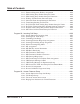
Charts and Illustrations N2IP-7 1 13 2 14 3 15 4 16 5 17 6 18 7 19 8 20 9 21 10 22 11 23 12 24 Figure 4: 24-BUTTON DSS CONSOLE Aspire Software Manual Features ◆ 67
Charts and Illustrations Line Keys/ Programmable Function Keys 0893200 - 3 L1 L2 1 2 CALL 1 3 CALL 2 4 5 6 7 8 9 DIAL Dual Line Appearance Keys Abbreviated Dialing FLASH 0 VOL LND MIC DND SPK HOLD Do Not Disturb Microphone Cutoff Speakerphone Microphone Last Number Redial Figure 5: Digital Two-Button Telephone 68 ◆ Features Aspire Software Manual
Charts and Illustrations 1 0893408 - 1 8 900MHz DIGITAL 9 10 2 3 4 HOLD CONF TRANSFER 5 ON/OFF MUTE 11 REDIAL TALK RING /VOL CH 1 2abc 3def 4ghi 5 jkl 6mno 7pqrs 8 tuv 9 wxyz 12 13 0oper 6 7 1. Headset Jack 2. Message Display 3. Hold Key 4. Talk Key 5. Numeric Keypad 6. Function keys (default: line keys 1-4) 7. Microphone 8. Volume (Ring/Vol) Key 9. Mute Key 10. Conference (CONF) Key 11. Transfer/Flash Key (defined in 15-02-05) 12.
Charts and Illustrations 0893408-2 8 ON OFF 1 2 HOLD 3 4 5 TALK CONF TRANSFER CHAN REDIAL 1 2 abc 3 def 4 ghi 5 jkl 6 mno 8 tuv 9 wxyz 0 oper # 7pqrs 6 9 10 11 12 13 14 R/VOL MUTE 7 1. Ringer ON/OFF switch 2. Message Display 3. Hold Key 4. Talk Key 5. Numeric Keypad 6. Function Keys (default: line keys 1-4) 7. Microphone 8. Headset Jack 9. Volume (R/VOL) Key 10. Mute Key 11. Conference (CONF) Key 12. Transfer/Flash Key (defined in Pgm 15-02-05) 13.
Charts and Illustrations Figure 8: Aspire Wireless Telephone Aspire Software Manual Features ◆ 71
Charts and Illustrations - For Your Notes - 72 ◆ Features Aspire Software Manual
Abbreviated Dialing Abbreviated Dialing Aspire S Aspire M/L/XL • Available. • Available. • 2000 bins available (0000-1999) for Common and Group Abbreviated Dialing. Up to 8 Abbreviated Dialing Groups available. • 2000 bins available (0000-1999) for Common and Group Abbreviated Dialing. Up to 64 Abbreviated Dialing Groups available. Description Abbreviated Dialing gives an extension user quick access to frequently called numbers.
Abbreviated Dialing Using a Programmable Function Key To streamline frequently-called numbers, an Abbreviated Dialing Programmable Function Key can also store an Abbreviated Dialing bin number. When the extension user presses the key, the phone automatically dials out the stored number. This provides true one-touch calling via a phone’s function keys. Conditions None Default Setting Available. There are no Group Abbreviated Dialing bins assigned.
Abbreviated Dialing ➻ ➻ ➻ ➻ ➻ ➻ ➻ ➻ 15-07-01 : Programming Function Keys Assign a function key for Common Abbreviated Dialing (code 27 ) or Group Abbreviated Dialing (code 28). You can program the key as either a general Abbreviated Dialing key or you can choose to store a bin number with the function key. This key would then always dial the associated bin number. If storing a bin number along with the code, do not store 0, 00 or 000.
Abbreviated Dialing Toll Restriction Toll Restriction may prevent a user from using a stored Abbreviated Dialing number. Trunk Group Routing Unless a user preselects a trunk, Trunk Group Routing selects the trunk Abbreviated Dialing uses for trunk calls. Operation To store an Abbreviated Dialing number (display phones only): 1. 2. 3. 4. 5. 6. Press idle CALL key. Dial 853 (for common) or 854 (for group). Dial common or group storage code (000-999).
Abbreviated Dialing To dial a Common Abbreviated Dialing number: Four-digit bin numbers must be dialed using the keyset’s Soft Keys. 3-Digit Bin Numbers Only 1. At keyset, press idle CALL key. OR At single line set, lift handset. 2. Dial #2 (000-999). OR Press DIAL key. OR Press Common Abbreviated Dialing key (PGM 15-07 or SC 851: 27). To preselect, press a line key in step 1 (instead of CALL) before pressing the DIAL or Abbreviated Dialing key). 3. Dial Common Abbreviated Dialing storage code (000-999).
Abbreviated Dialing To dial a Group Abbreviated Dialing number: 3-Digit Bin Numbers Only 1. At keyset, press idle CALL key. OR At single line set, lift handset. 2. Dial #4 (000-999). OR Press DIAL key. OR Press Group Abbreviated Dialing key (PGM 15-07 or SC 851: 28). To preselect, press a line key in step 1 (instead of CALL) before pressing the DIAL or Abbreviated Dialing key) 3. Dial the Group Abbreviated Dialing code (000-999). The stored number dials out.
Account Codes Account Codes Aspire S Aspire M/L/XL • Available. • Available. • Adjustable Forced Account Code interdigit timer requires software 2.65+. • Adjustable Forced Account Code interdigit timer requires software 2.65+. Description Account Codes are user-dialed codes that help the system administrator categorize and/or restrict trunk calls.
Account Codes Timer Modified to Allow for Forced Account Code Interdigit Timer Programming has been changed which will allow the adjustment of the interdigit timer used for Forced Account Codes. Previously, this was fixed at 3 seconds. Depending on your software, the system will use the time set in Program 21-01-04 : System Options for Outgoing Calls - Dial Tone Detection Time for the interval the system will wait for a user to enter a Forced Account Code.
Account Codes Conditions (A.) If a user enters a code that exceeds the 16 digit limit, the system ignores the Account Code entry. (B.) If the system has Account Codes disabled, the digits dialed (e.g., *1234*) appear on the SMDR report as part of the number dialed. (C.) Do not use an asterisk within a PBX access code when using Account Codes. Otherwise, after the *, the trunk will stop sending digits to the central office. Default Setting Account Codes are disabled.
Account Codes Related Features Abbreviated Dialing Abbreviated Dialing bins can contain stored Account Codes. Prevent them from being displayed using 20-07-04. Automatic Route Selection ARS can force a user to enter an Authorization Code prior to using a certain route. The system verifies the ARS Authorization Code dialed against the ARS Authorization Code list (Program 44-03). One-Touch Calling To simplify Account Code entry, store the Account Code (e.g., *1234*) in a One-Touch Key.
Account Codes To enter an Account Code before dialing the outside number: 1. 2. 3. 4. 5. If your system has Forced Account Codes, you must use this procedure. If it has Verified Account Codes, you can use this procedure instead of letting the system prompt you for your Account Code. You may also use this procedure if your system has Optional Account Codes. If your system has Verified Account Codes enabled, be sure to choose a code programmed into your Verified Account Code list.
Account Codes To enter an Account Code for an incoming call: 1. 2. 3. 4. This procedure is not available at SLTs. Answer incoming call. If Account Codes for Incoming Calls is disabled, the following steps will dial digits out onto the connected trunk. Dial *. Enter the Account Code. You can enter any code of the proper length. Incoming Account Codes cannot be Forced or Verified. Dial *. To enter an Account Code while placing a trunk call: 1. 2. 3. 4. 5.
Alarm Alarm Aspire S • Available. Aspire M/L/XL • Available. Description Alarm lets a keyset extension work like an Alarm clock. An extension user can have Alarm remind them of a meeting or an appointment. There are two types of Alarms: ● Alarm 1 (sounds only once at the preset time) ● Alarm 2 (sounds every day at the preset time) Conditions Single line sets will ring and Music on Hold will be heard when the alarm sounds. Default Setting Alarm is enabled.
Alarm Operation To set the alarm: 1. 2. 3. 4. 5. At keyset, press idle CALL key. OR At single line set, lift handset. Dial 827. Dial alarm type (1 or 2). Alarm 1 sounds only once. Alarm 2 sounds each day at the preset time. Dial the alarm time (24-hour clock). For example, for 1:15 PM dial 1315. A confirmation tone will be heard if the alarm has been set. If the alarm was not set, an error tone will be heard instead. At keyset, press SPK to hang up. OR At single line set, hang up. To silence an alarm: 1.
Alarm Reports Alarm Reports Refer to the Maintenance (page 391) for information on this feature.
Alphanumeric Display Alphanumeric Display Aspire S Aspire M/L/XL • Available. • Available. • Additional language options (entries 10-12 in Program 15-02-01) require software 4.93+. • Additional language options (entries 10-12 in Program 15-02-01) require software 4.93+. Description Multibutton display telephones have a 3-line, 24 character per line alphanumeric display that provides various feature status messages.
Analog Communications Interface (ACI) Analog Communications Interface (ACI) Aspire S • Available - 8 ACI software ports (4 PGDAD modules max. when used for ACI ports) and 4 ACI Department Groups. Aspire M/L/XL • Available - 96 ACI software ports (48 PGDAD modules max. when used for ACI ports) and 16 ACI Department Groups.
Analog Communications Interface (ACI) By using Department Calling, you can arrange multiple tape recorders into a pool. When an extension user dials the Department Group pilot number, they reach the first available tape recorder in the pool. The relays in the PGDAD module can optionally control customer-provided external ringers (loud bells) and buzzers. When an extension user dials the ACI analog port extension number, the associated PGDAD relay closes and activates the ringer.
Analog Communications Interface (ACI) PGDAD/ACI Interface Specifications Relay Contacts Maximum Contact Ratings 30 V DC @ 60 mA 90 V AC @ 10 mA Minimum Application Load 1 V DC @ 1 mA Audio/Music Input Input Impedance 47 K Ohms @ 1 KHz Audio/Paging Output Output Impedance 600 Ohms @ 1 KHz Maximum Output + 8 dBm Default Setting No PGDAD modules programmed.
Analog Communications Interface (ACI) ➻ ➻ ➻ ➻ ➻ ➻ ➻ ➻ ➻ ➻ 92 ◆ Features 14-09-01 : ACI Conversation Recording Destination for Trunks - ACI Recording Destination Extension Number Use this option to assign the ACI Call Recording destination on a per trunk basis. The destination can be an ACI port’s extension number (assigned in Program 11-06-01) or an ACI Department Group pilot number (assigned in Program 11-08-01).
Analog Communications Interface (ACI) Related Features Automatic Call Distribution (ACD) ACD agents which are logged on can be recorded. Background Music ACI software ports cannot be Background Music music sources. Door Box If a 2PGDAD circuit is used for ACI, it can not be used for a Door Box. Hotline Music on Hold ACI software ports can be Music on Hold music sources. One-Touch Calling An extension can have One-Touch Keys for ACI software ports.
Aspire Wireless Aspire Wireless Aspire S • Not Available. Aspire M/L/XL • Available with software 2.16+ - 120 wireless phones maximum • Program options to adjust transmit and receive level of Aspire Wireless available with 2.63+ software. • Service Codes for registering/unregistering Aspire Wireless phones available with 2.63+ software. • Enhanced Features requires software 4.93+, Aspire Wireless handset version PP4+, and DSIU firmware 1.16+.
Aspire Wireless Out-of-Range When a Aspire Wireless phone receives an incoming call and the phone is considered out-of-range (Program 20-22-05 timer expires), what the system does with the call and what the caller hears depends on system programming. ● ● ● ● Extension callers will hear a lock-out tone and may see “Out of Range” on their display. DISA callers will following the programming set in Program 25-04-01 : VRS/DISA Transfer Ring Group With No Answer/Busy.
Aspire Wireless Enhanced Features Added The features for the Aspire Wireless phones have been enhanced. Note: In order to enable these enhancements, the Aspire Wireless phones must be updated to software version PP4 and the DSIU PCB must be updated to 1.16 or higher. When both the handset and DSIU are updated to the correct version, Program 90-17-15 will display the version as V01.07.
Aspire Wireless Related Features Caller ID Aspire Wireless phones can provide Caller ID information if it is provided by telco. Call Forwarding ● If the Transferring When Out of Range feature and a Call Forward option (such as No Answer) are both programmed for the Aspire Wireless (DECT) phone, the call is sent to the destination based on which option’s timer expires first.
Aspire Wireless Picking up calls not ringing your phone . . . Answering a call ringing Paging after hours: 1. 2. Press the ON-HOOK/OFF-HOOK key. Dial # + 0. When a call is ringing a co-worker’s phone: 1. 2. Press the ON-HOOK/OFF-HOOK key. Dial ** + Co-worker’s extension. Placing Calls Placing an Outside Call: 1. 2. Press the ON-HOOK/OFF-HOOK key. Listen for dial tone. To preview the number first, press the ON-HOOK/OFF-HOOK key after step 2 instead of pressing it first. Dial 9 + Outside number.
Aspire Wireless Abbreviated Dialing: Common and Group (Speed Dial) Store Common or Group Abbreviated Dialing numbers: 1. 2. 3. 4. Press the ON-HOOK/OFF-HOOK key. Dial 853 (for Common). OR Dial 854 (for Group). Dial Abbreviated Dialing bin number. Ask your Communications Manager for your bin numbers. Dial phone number to store + the R (HOLD/RECALL) key. The number can be up to 24 digits, using 0-9, # and *. Dial your stored Abbreviated Dial number: 1. 2. Press the ON-HOOK/OFF-HOOK key.
Aspire Wireless 5. Press the OK button. INPUT DATA ABB:COMMON 6. Input the character(s) by pressing dial pad. N While inputting characters, the cursor blinks. While scrolling through the characters, you have approximately 1 second to move to the next character under the same key, otherwise, the phone accepts the displayed character as an entry. You can use the left and right arrows to move the cursor.
Aspire Wireless 7. Press the OK button to start the search. NEC-ABC 0123451111 8. The display shows the ABB/EXT name in the first line (Max. 12 characters). The ABB/EXT number is shown in the second and third line (Max. 20 digits). If there is no match for the search entry, the following display is shown: UNLISTED- 9. Press the right arrow button to see the next entry in the search list. NEC-DEF 0123452222 10. To make an outgoing call, press the hook button .
Aspire Wireless Use the Phone’s Telephone Book for Personal Numbers Store a number in the Telephone Book: 1. 2. 3. While idle, dial the number to be stored. Press the > key + the OK key. Enter the name associated with the number + the OK key. Up to 80 numbers with name can be stored in the Telephone Book. A name is required with each number. A “Memory Full” message indicates that a number must be deleted before making another entry. Dial a number from the Telephone Book: 1. 2. 3. Press the > key.
Aspire Wireless Camp On / Callback If you heard a busy signal when calling a co-worker, use Camp On or Callback: 1. 2. Dial 2 to Camp On (wait without hanging up). (Intercom calls) If you hear two beeps, you can speak. If you hear busy/ring, dial 6 to send a Voice Over. (Outside calls) When you hear new dial tone, place your call again. OR Dial 2 and hang up to leave a Callback for a free line or extension. Wait for the system to call you back.
Aspire Wireless Turning your handset on: 1. Press the ON-HOOK/OFF-HOOK key. When the handset is on, is shown in the lower left corner of the display if the handset has been subscribed to a system. Hold Placing a call on Hold: 1. Do not hang up + press the R (HOLD/RECALL) key + Do not hang up. This puts your call on Exclusive Hold. To place the call on Group Hold (so only those in your Department can pick up the call), dial 832 after pressing the R (Hold/Recall) key.
Aspire Wireless Name Entry: The dial pad digits are used for writing the name to be placed in the Phone Book. For example, press the digit 2 key once for A, twice for B, three times for C, etc. The arrow keys can be used to move the cursor left or right. The left arrow key can also be used for deleting a character by holding it down for 1 second. Pressing a new key or pausing for more than 1 second automatically moves the cursor to the next position. Park Park a call in orbit: 1. 2. 3. 4. Do not hang up.
Aspire Wireless Park and Page Use Park and Page to be paged for calls while away from your desk 1. 2. 3. 4. 5. Press the ON-HOOK/OFF-HOOK key. Press *47 + Record your Personal Greeting. #7 + Record the Page. For Personal Greeting only, press # then 2 (Busy/No Answer), 4 (Immediate), or 6 (No Answer) + extension to receive calls + 2 (All) or 3 (CO) and hang up. # + Dial the Page Zone (e.g. 801 + 1). Press 2 (All calls) or 3 (CO calls). To Cancel: 1. Press the ON-HOOK/OFF-HOOK key. 2. 3. Press *47 3.
Aspire Wireless Registration Registering an Aspire Wireless Handset 1. 2. 3. 4. 5. 6. 7. 8. 9. To cancel the registration process at any point, press the SPK or Headset key, or place the handset on-hook. From a keyset, press SPK key and dial the service code defined in Program 11-10-30. Enter the extension number to be assigned. If the DSIU is unavailable or if the extension number is invalid, the system displays an error message and the phone is returned to an idle condition.
Aspire Wireless Save Save your call for quick dialing later on: 1. While on a call, press the R (HOLD/RECALL) key + 815. Quickly redial your saved number: 1. Press the ON-HOOK/OFF-HOOK key + 815. When redialing, the system selects an outside line for you. To clear a saved number: Press the ON-HOOK/OFF-HOOK key + 885. Transfer Transferring your call to a co-worker: 1. 2. 3. Press the R (HOLD/RECALL) key + Dial your co-worker’s extension.
Aspire XL Aspire XL Aspire S • N/A Aspire M/L/XL • Aspire XL available with software 4.0E+. Description To enhance the Aspire system, which previously only supported 256 digital/analog extensions (not including IP and Wireless), the Aspire XL system is now available. The Aspire XL uses a new power supply cabinet, new power supplies, and 32ESIU PCB to provide the ability to support up to 384 digital/analog extensions (TDM/legacy telephones).
Aspire XL ● Power Supply Cabinet (IP1WW-XLPS CABINET/ For the IP1WW-PSADU-A1) - P/N 0890068 IP1WW-XLPSU CABINET can contain maximum two IP1WW-PASDU-A1s. The cabinet accommodates up to two AC/DC power supplies. This cabinet is to be installed as the bottom cabinet of a 3-cabinet system (the top two cabinets containing the NTCPU, DC/DC Converters, and PCBs). Refer to the Aspire XL Installation Instructions, P/N 0893113, for details on installing the power supplies and cables.
Aspire XL The Aspire XL system can support mixed hardware configurations. With an Aspire XL AC/ DC power supply cabinet and DC/DC Converter, the second cabinet can contain up to two Aspire M/L power supplies (P/N 0891000). For installation details, refer to the Aspire 32ESIU PCB Installation Instructions, P/N 0893112. Program Changes The following programs are enhanced for the XL system.
Aspire XL Conditions ● ● ● Prior to updating system software, due to capacity differences, a database file must be made in order to revert to any older version of software. The expanded database file from a 4.x software cannot be used in older software once the new ports are recognized and used by the system. APR(B2 mode) Port Assignment: With the XL system, the APR port is assigned from 512 in descending order. The Aspire XL system can support mixed hardware configurations.
Attendant Call Queuing Attendant Call Queuing Aspire S • Available. Aspire M/L/XL • Available. Description Attendant extensions can have up to 32 incoming calls queued before additional callers hear busy tone. This helps minimize call congestion in systems that use the attendant as the overflow destination for unanswered calls. For example, you can program Direct Inward Lines and Voice Mail calls to route to the attendant when their primary destination is busy.
Automatic Call Distribution (ACD) Automatic Call Distribution (ACD) Aspire S • Not Available. Aspire M/L/XL • Available with the Basic NTCPU (P/N 0891002) with the PAL upgrade or the Enhanced NTCPU (P/N 0891038) - 64 ACD Groups and 512 ACD Agents. • ACD Call Coverage keys supported with 1.06+ software. • ACD Queue Status Display supported with 1.11+ software. • ACD Hotline Key Shows Agent Status supported with 1.11+ software. • ACD MIS software can count overflow calls with 2.63+ software.
Automatic Call Distribution (ACD) For each ACD Group, you can set the following conditions: - The number of trunks that can wait in queue before the Queue Status Display occurs. - How often the time in queue portion of the display reoccurs. - If the supervisor should hear a Queue Alarm whenever the time in queue portion reoccurs. This alarm is a single beep tone that reminds the supervisor to check the condition of the queue.
Automatic Call Distribution (ACD) ● ● ● During Mode Pattern 1, ACD agents will belong to ACD groups 1, 2, and 16 at the same time. During Mode Pattern 2, ACD agents will belong to only ACD group 1. During Mode Pattern 3-8, ACD agents will not belong to any ACD group and the ACD extensions will work as normal extensions. Example 2: Log In with AIC 567 ● During Mode Patterns 1-8, ACD agents will belong to only ACD group 10.
Automatic Call Distribution (ACD) ● Emergency Call If an ACD Agent needs assistance with a caller, they can place an Emergency Call to their ACD Group Supervisor. Once the supervisor answers the Emergency Call, they automatically monitor both the ACD Agent and the caller. If the agent needs assistance, the supervisor can join in the conversation. Emergency Call can be a big help to inexperienced ACD Agents that need technical advise or assistance with a difficult caller.
Automatic Call Distribution (ACD) ● Rest Mode Rest Mode temporarily logs-out an ACD agent’s phone. There are two types of Rest Mode:- Manual Rest Mode An ACD Agent can enable Manual Rest Mode anytime they want to temporarily log out of the ACD Group. They might want to do this if they go to a meeting or get called away from their work area. While logged out, calls to the ACD Group will not ring the agent’s phone.
Automatic Call Distribution (ACD) ● Work Time Work Time temporarily busies-out an ACD agent’s phone so they can work at their desk uninterrupted. This gives the agent time to fill out important logs and records as soon as they are finished with their call. There are two types of Work Time: - Manual Work Time An ACD Agent can enable Manual Work Time any time they need to work at their desk undisturbed.
Automatic Call Distribution (ACD) BLF For Co-Workers That Are Not ACD Agents When the key is . . . Your co-worker is . . . Off Idle On Busy or ringing Fast Flash In Do Not Disturb — All calls (option 3) or Intercom calls (option 2) - Enhanced Supervisor Options An ACD supervisor can individually assign extensions to ACD Groups, and set an agent’s status once assigned. This provides the supervisor with tremendous flexibility to reassign agents as work loads vary.
Automatic Call Distribution (ACD) 2 Queue Status displays and Alarm Send (41-20-05) starts. 3 6 Alarm ends. 4 Pattern repeats. Queue Status Display ends. 41-20-05 41-20-05 41-20-02 41-20-02 41-20-03 41-20-03 1 Call queues and 41-20-03 starts. 5 Time in queue refreshes on display and queue alarm sounds (if enabled).
Automatic Call Distribution (ACD) (D.) In order to scroll through the ACD groups queue status, the Queue Status Display Programmable Function key must be used. You cannot scroll when the Queue Status Display appears due to an alarm condition. (E.) If the Queue Status display and alarm are active and the queued called is answered/ disconnected, the display and alarm will continue until the timers in Program 41-0202 and 41-20-05 expire. (F.
Automatic Call Distribution (ACD) The system can now allow either an off-premise number (using a programmed Abbreviated Dial number) or incoming ring group for the ACD Overflow Transfer destination. Notes: When using Off-Premise Overflow transfer and if all trunks are busy, the system will set the ACD Overflow Timer again and wait to retry. When this occurs, the queue information of this call will be set to the oldest queue.
Automatic Call Distribution (ACD) Programming Refer to the ACD Manual (P/N 0893202) for complete programming details. ➻ ➻ ➻ ➻ ➻ ➻ ➻ ➻ ➻ ➻ ➻ ➻ ➻ 124 ◆ Features 11-13-01 - 11-13-13 : Service Code Setup (For ACD) If required, customize the service codes which are used with the ACD feature. Note that when using service code 169 to change an agent’s ACD group, the supervisor must enter a 2-digit number for the group. For example, to change to ACD group 4, the entry would be ‘169 04’.
Automatic Call Distribution (ACD) ➻ ➻ ➻ ➻ ➻ ➻ ➻ ➻ ➻ ➻ ➻ ➻ Aspire Software Manual 20-13-33 : Class of Service Options (Supplementary Service) - ACD Supervisor’s Position Enhancement This option must be enabled in order for the operator to use service codes in Program 11-1310 through 11-13-13. 30-01-01 : DSS Console Operating Mode Set the mode of the system’s DSS Consoles. The available options are Regular (Business) Mode (0), Hotel Mode (1), and ACD Monitor Mode (2).
Automatic Call Distribution (ACD) ➻ ➻ ➻ ➻ ➻ ➻ ➻ ➻ ➻ ➻ ➻ ➻ ➻ 126 ◆ Features 41-05-01 : ACD Agent Work Schedules Set up the Work Schedules for ACD Agents and Groups. For each ACD Work Schedule (1-4), designate the start and stop times for each of the eight Work Periods. Once you set up the schedules in this program, assign them to days of the week in Program 41-07. (This is the same program used by the Trunk Work Schedules.) 41-06-01 : Trunk Work Schedules Set up the Work Schedules for trunks.
Automatic Call Distribution (ACD) ➻ ➻ ➻ ➻ ➻ ➻ ➻ ➻ ➻ ➻ ➻ ➻ ➻ ➻ ➻ Aspire Software Manual 41-10-04 : PGDAD Delay Announcement - 2nd Delay Announcement Connection Timer For each ACD group (01-64), set the timer the system waits before playing the second delay announcement (0-64800 seconds). 41-10-05 : PGDAD Delay Announcement - 2nd Delay Announcement Sending Duration For each ACD group (01-64), set the timer for the 2nd Delay announcement (0-64800 seconds). Once this timer expires, the call will disconnect.
Automatic Call Distribution (ACD) ➻ ➻ ➻ ➻ ➻ ➻ ➻ ➻ ➻ ➻ ➻ ➻ ➻ 128 ◆ Features 41-14-02 : ACD Options - Wrap Up Mode Set the Wrap Up Mode option (0=After wrap up mode key is pressed, 1=After call is finished automatically) for ACD Groups (01-64). Use Program 15-07 to assign an ACD Wrap-Up Mode key (*17) to ACD agents. 41-14-03 : ACD Options - ACD Priority for Overflow Calls Set the priority for overflow calls (0=own group priority, 1=priority set by Program 41-03-03) for ACD Groups (01-64).
Automatic Call Distribution (ACD) ➻ ➻ ➻ ➻ ➻ ➻ ➻ ➻ ➻ ➻ ➻ ➻ ➻ ➻ ➻ ➻ Aspire Software Manual 41-17-01 : ACD Login Mode Setup Define the ACD login mode (0=normal, 1=AIC) for each extension. If set to ‘1’: - Program 41-02-01 is used. - Note that a supervisor can not log in/out an AIC member as they are not normal ACD agents. - Service codes for log-in/log-out must be defined in Programs 11-13-08 and 11-13-09. If set to ‘2’: - Program 41-18-01 is used.
Automatic Call Distribution (ACD) ➻ ➻ ➻ ➻ ➻ ➻ ➻ ➻ 41-19-06 : Voice Mail Delay Announcement - Tone Kind at Message Interval For each ACD Group (01-64), define the what the caller will hear between the messages (0=ring back tone, 1=MOH, 2=BGM). Currently, calls in the ACD queue will only hear MOH if the music is from the NTCPU. It will not work if the MOH is connected to an ACI. Incoming callers which have not been put into queue, however, can hear the MOH from any source.
Automatic Call Distribution (ACD) Operation Transferring Calls to an ACD Group To Transfer a call to an ACD Group: 1. 2. 3. At keyset or DSL, press HOLD. OR At SLT, hookflash You hear Transfer dial tone. Dial ACD Group Master Number. You can press a One-Touch Key for the master instead. Hang up. Transferring Trunk Calls to the ACD Master (Program 15-02-21 = 0): 1. 2. 3. Only analog, ISDN, or H.323 trunk calls can be transferred. While on an outside call, press HOLD. Press the ACD Call Coverage key.
Automatic Call Distribution (ACD) Agent Log In and Log Out To log your extension into the ACD Group: Keyset 1. 2. Your display shows: WAIT ACD LOGIN. If Program 12-07-01 has a customized Day/ Night mode message defined, the ACD agent’s display will not indicate the WAIT ACD LOGIN status (however, the agent may still log in using the following procedure). Press idle CALL key. Dial *5. You hear confirmation tone. OR Press ACD Log On/Off key (PGM 15-07-01 or SC 852: code *10). You hear a single beep.
Automatic Call Distribution (ACD) AIC Agent Log In To log in: Keyset 1. Press the ACD Log In/Log Out key (Program 15-07 or SC 852: *10). OR 1. Press CALL key and dial the AIC Log In service code (Program 11-13-08). 2. If the agent log in code is used (as with inDepth/inDepth+), enter the agent log in code (the number of digits to be entered is determined by Program 41-01-02). Otherwise, skip to Step 3. 3. Dial the Agent Identity Code (AIC) (up to 4 digits) defined in Program 41-18-01.
Automatic Call Distribution (ACD) Multiple Agent Log In To log in: Keyset 1. Press the ACD Log In/Log Out key (Program 15-07 or SC 852: *10). 2. Dial 0 to cancel the log out option. 3. Dial the Agent Identity Code (AIC) (up to 4 digits). The ACD Log In/Log Out key lights. OR 1. Press CALL key and dial the AIC Log In service code (Program 11-13-08). 2. Dial the Agent Identity Code (AIC) (up to 4 digits). The ACD Log In/Log Out key lights. DSL 1.
Automatic Call Distribution (ACD) Changing ACD Group Assignment To change your ACD Group Assignment: 1. 2. 3. 4. 5. Log out of your ACD Group (see the instructions above). Press idle CALL key. Dial 170. Dial the number of the ACD Group (1-64) into which you want to log. You hear confirmation tone. Log into the new ACD Group (see the instructions above). Using the Headset with Automatic Answer for ACD Agents: 1. 2. 3. With the keyset in an idle state, press the Check key.
Automatic Call Distribution (ACD) Queue Status Display When Logged Into ACD Group 1. 2. 3. With an idle keyset, press the Queue Status Display Programmable Function Key (Code: *19). The display indicates the number of calls in queue, the trunk name, and the length of time the call has been waiting. When the Queue Status Display key is pressed, the queue status of the extension’s group is displayed. When the extension is not in an ACD group, the Queue Status of group 1 is displayed instead.
Automatic Call Distribution (ACD) To cancel the manual Rest Mode/Off-Duty Mode: Keyset 1. Press the ACD Rest Mode key (PGM 15-07 or SC 852: *13). The ACD Rest Mode key light goes off. Single Line Telephone 1. Lift the handset. A fast busy is heard. 2. Dial 159. 3. Hang up. Refer to the ACD Manual (P/N 0893202) for additional operations.
Automatic Route Selection Automatic Route Selection Aspire S Aspire M/L/XL • Available. • Available. • COS option for outgoing calls following access map is available. • COS option for outgoing calls following access map is available in software 1.11+. • COS Matching feature is available with 2.63+ software. • COS Matching feature is available with 2.63+ software. • Alternate Carrier Access for ISDN trunks requires software 2.
Automatic Route Selection Class of Service Option Allows Outgoing Calls to Not Follow Access Map Using this option allows an extension’s Class of Service to be set so that ARS does not follow the trunk access map settings (Program 14-07-01 and 15-06-01). The feature allows an extension user to have CO line keys on their phone which allow incoming access only. The user would only have outgoing access on the CO lines when using ARS to place a call.
Automatic Route Selection With Program 26-01-06: ARS COS Match Access disabled (set to '0'): ● If at 9:00 AM, each extension dialed '9+(203)926-5400' All Extension would use Trunk Group 3 ● If at 9:00 AM, each extension dialed '9+(214)262-2000' All Extension would use Trunk Group 1 ● If at 6:00 PM, each extension dialed '9+(203)926-5400' All Extension would use Trunk Group 3 ● If at 6:00 PM, each extension dialed '9+(214)262-2000' Extension 301, 302 and 401 would use Trunk Group 1 Extension 402 would n
Automatic Route Selection ➻ Program 26-02 for Dial Analysis Table for ARS/LCR set as: Table No. Program 26-02-01 Dial Program 26-02-02 Service Type Program 26-02-03 Add Data Program 26-02-04 ARS COS Program 26-02-05 Dial Treatment 1 203@@@@@@@ 1:TRG 1(Group 1) 0 1 2 @@@@@@@@@@ 1:TRG 1(Group 1) 0 0 ➻ ➻ Program 26-03-01 for ARS Dial Treatments set as: Table No. 1 - Dial Treatment: A1RE Program 26-11-01 for Transit Network ID Table set as: Table No.
Automatic Route Selection ➻ ➻ ➻ ➻ ➻ ➻ ➻ ➻ ➻ 142 ◆ Features 20-03-04 : System Options for Single Line Telephones - Dial Sending Start Time for SLT or ARS When ARS or an analog extension user accesses a trunk and dials an outside call, the system waits this interval before outdialing the first digit (0-64800 seconds). 20-06-01 : Class of Service for Extensions Assign a Class of Service (1-15) to an extension.
Automatic Route Selection ➻ ➻ ➻ ➻ ➻ ➻ ➻ ➻ ➻ Aspire Software Manual 26-02-03 : Dial Analysis Table for ARS - Additional Data / Service Number For each Dial Analysis Table (1-200), if Service Type 1 was selected in Program 26-02-02, enter the trunk group number (0-100, 0=no route). 26-02-04 : Dial Analysis Table for ARS - ARS Class of Service For each Dial Analysis Table (1-200), set the Automatic Route Selection (ARS) Class of Service (0-16).
Automatic Route Selection ➻ ➻ ➻ ➻ ➻ ➻ ➻ ➻ ➻ ➻ ➻ ➻ ➻ ➻ ➻ 144 ◆ Features 44-02-03 : Dial Analysis Table for ARS/F-Route Access - Additional Data If a Service Type is selected in Program 44-02-02, set the additional data, if required, for the Pre-Transaction Table for selecting ARS/F-Route (24 digits max: 1-9, 0 * #, @). To enter a wild card/don’t care digit, press Line Key 1 to enter an @ symbol.
Automatic Route Selection ➻ ➻ 44-06-01 : Additional Dial Table If an Additional Dial Number Table is entered in Program 44-05-03, define the additional dial table (1-1000) to add digits in front of the dialed ARS/F-Route number (24 digits max: 1-9, 0 * #, Pause). To enter a wild card/don’t care digit, press Line Key 1 to enter a P (pause) symbol.
Automatic Route Selection Trunk Group Routing A system with Automatic Route Selection cannot also have Trunk Group Routing. Trunk Queuing/Camp On With ARS installed, Trunk Queuing automatically queues for the least costly route. The system automatically redials the queued call when the extension user lifts the handset. Operation To place a call using ARS: 1. 2. 3. 146 ◆ Features At keyset, press idle CALL key. OR At single line set, lift handset. You’ll hear normal Intercom dial tone. Dial 9.
Background Music Background Music Aspire S • Available. Aspire M/L/XL • Available. Description Background Music (BGM) sends music from a customer-provided music source to speakers in keysets. If an extension user activates it, BGM plays whenever the user’s extension is idle. Conditions (A.) Background Music requires a customer-provided music source connected to the Aspire NTCPU’s CN16 connector or the Aspire S CPU’s CN23 connector. Refer to the system Hardware Manual. (B.
Barge In Barge In Aspire S • Available. Aspire M/L/XL • Available. Description Barge In permits an extension user to break into another extension user’s established call, including Conference calls. This sets up a Conference-type conversation between the intruding extension and the parties on the initial call. With Barge In, an extension user can get a message through to a busy co-worker right away. There are two Barge In modes: Monitor Mode (Silent Monitor) and Speech Mode.
Barge In ➻ ➻ ➻ ➻ ➻ ➻ ➻ ➻ 20-13-10 : Class of Service Options (Supplementary Service) - Barge In Mode In an extension’s Class of Service, enable the Barge In Speech Mode (0) or Monitor Mode (1) at the initiating extension (i.e., Barge In initiator). 20-13-15 : Class of Service Options (Supplementary Service) - Barge In, Initiate In an extension’s Class of Service, enable (1) or disable (0) Barge In at the initiating extension (i.e., Barge In initiator).
Barge In Operation To Barge In after calling a busy extension: The call must be set up for about 10 seconds before you can Barge In. Listen for busy/ring or busy tone. 1. Call busy extension. 2. Press Barge In key (PGM 15-07 or SC 851: 34). To Barge in without first calling the busy extension: 1. 2. 3. 1. 2. Press idle CALL key. Dial 810. OR Press Barge In key (PGM 15-07 or SC 851: 34). Dial busy extension.
Call Coverage Call Coverage Please refer to the Multiple Directory Numbers / Call Coverage (page 419) for information on this feature.
Call Duration Timer Call Duration Timer Aspire S Aspire M/L/XL • Available. • Available. • Program 20-09-06 requires software 2.67+. • Program 20-09-06 requires software 2.67+. Description Call Duration Timer lets a keyset user time their trunk calls on the telephone display. This helps users that must keep track of their time on the phone. For incoming trunk calls, the Call Timer begins as soon as the user answers the call.
Call Forwarding Call Forwarding Aspire S Aspire M/L/XL • Available. • Available. • Activating Call Forwarding while on a call available with 2.63+ software. • Activating Call Forwarding while on a call available with 2.63+ software. Description Call Forwarding permits an extension user to redirect their calls to another extension. Call Forwarding ensures that the user’s calls are covered when they are away from their work area.
Call Forwarding When Call Forward Follow Me is set up in a chain, forwarding cannot be canceled by the middle keyset (as shown in the example below) while on a call. Keyset A sets Follow Me forwarding for Keyset B Keyset A Keyset B sets Follow Me forwarding for Keyset C Keyset B Keyset C Conditions (A.) Normally, the system does not allow the chaining of Call Forwards. For example, extension 316 forwards to 318, and 318 in turn forwards to 320. Calls to 316 route to 318. Calls to 318 route to 320.
Call Forwarding Programming ➻ 11-11-01 : Service Code Setup (for Service Access) - Call Forward, Immediate ➻ ➻ ➻ ➻ ➻ ➻ 11-11-02 : Service Code Setup (for Service Access) - Call Forward, Busy 11-11-03 : Service Code Setup (for Service Access) - Call Forward, No Answer 11-11-04 : Service Code Setup (for Service Access) - Call Forward, Busy/No Answer 11-11-05 : Service Code Setup (for Service Access) - Call Forward, Both Ring 11-11-06 : Service Code Setup (for Service Access) - Call Forward, Select Option 11
Call Forwarding Direct Station Selection (DSS) Console A DSS key will only indicate a Call Forwarding indication for extensions forwarded with Personal Answering Machine Emulation (*2 + 1) or Immediate Call Forwarding (*2 + 4). Do Not Disturb If an extension user activates DND option 4, the system prevents other extensions from forwarding calls to them. If an extension already receiving forwarded calls activates DND option 4, callers to the forwarded extension hear DND tone.
Call Forwarding 2. 3. 1. 2. 3. 4. Dial 1 plus extension to enable; dial 0 to disable. Once you activate Call Forwarding, only your Call Forwarding destination can place an Intercom call to you. Dial destination extension, Voice Mail master number or press Voice Mail key. You’ll hear stutter dial tone when placing a new call. Your Call Forwarding Programmable Function Key flashes when Call Forwarding is activated.
Call Forwarding, Fixed Call Forwarding, Fixed Aspire S • Available. Aspire M/L/XL • Available. Description Fixed Call Forwarding is a type of forwarding that is permanently in force at an extension. Calls to an extension with Fixed Call Forwarding enabled automatically reroute - without any user action. Unlike normal Call Forwarding (which is turned on and off by extension users), Fixed Call Forwarding is set by the administrator in system programming.
Call Forwarding, Fixed Description (Cont’d) Fixed Call Forwarding Chaining Fixed Call Forward Chaining allows Fixed Call Forwards to loop from one extension to the next. For example, you could have the chain 301 ☞ 302 ☞ 303 ☞ 304 set up for Fixed Call Forwarding when Busy. If extension 301 is busy, calls to 301 route to 302. If 302 is also busy, the calls route to 303 and so on. Chaining allows you to set up very basic hunting between co-workers.
Call Forwarding, Fixed Programming ➻ 24-02-03 : System Options for Transfer - Delayed Call Forwarding Time ➻ ➻ Set the Delayed Call Forwarding interval. For an unanswered call, Fixed Call Forwarding When Unanswered occurs after this interval. 24-06-01 : Fixed Call Forwarding For an extension, assign the Fixed Call Forwarding Type (0-4) and the destination extension.
Call Forwarding, Off-Premise Call Forwarding, Off-Premise Aspire S Aspire M/L/XL • Available. • Available. • DSL sets can be used. • DSL sets can be used. Description Off-Premise (OPX) Call Forwarding allows an extension user to forward their calls to an off-site location. By enabling OPX Call Forwarding, the user can stay in touch by having the system forward their calls while they are away from the office.
Call Forwarding, Off-Premise (D.) Call Forwarding an extension in a Department Group will prevent that extension from receiving Department Pilot Calls. (E.) If a Programmable Function key is not defined for Call Forwarding (10 - 17), the DND key flashes to indicate that the extension is call forwarded. Default Setting Disabled. Related Features Call Forwarding, Fixed Fixed Call Forwarding can automatically forward an extensions calls to an outside number.
Call Forwarding, Off-Premise ➻ ➻ ➻ ➻ ➻ ➻ ➻ 15-07-01 : Programmable Function Keys For one-touch access to the Call Forwarding Device setup code (*4 ), assign a function key for Call Forwarding (Device). For Off-Premise Call Forwarding by a Door Box, assign a function key (54) if required. 20-06-01 : Class of Service for Extensions Assign Class of Service (1-15) to an extension.
Call Forwarding, Off-Premise Trunk-to-Trunk Forwarding - DID (3) Trunk Forwarding by Department Groups (in addition to above programming) Refer to Department Calling for additional Department Group programming. ➻ ➻ ➻ ➻ ➻ ➻ ➻ ➻ ➻ ➻ ➻ ➻ ➻ 164 ◆ Features 11-07-01 : Department Group Pilot Numbers Assign pilot numbers to the Extension (Department) Groups you set up in Program 16-02.
Call Forwarding, Off-Premise Trunk-to-Trunk Forwarding - DID (3) Trunk Forwarding Using DID Translation Table (in addition to above programming) Refer to Direct Inward Dialing (DID) for additional DID programming.
Call Forwarding, Off-Premise Off-Premise Call Forwarding for Door Boxes: These operations are performed at the Door Box Ringing Extension only. To activate Call Forwarding Off-Premise by Door Box 1. 2. 3. 4. At keyset, press idle CALL key + Dial 822. OR Press Call Forward (Device) key (PGM 15-07 or SC 851: 54) OR At SLT, lift handset + Dial 822. Dial the Door Box number (1-4 or 1-8). Dial the Abbreviated Dialing number to which the calls should be forwarded. Press SPK (or hang up at SLT) to hang up.
Call Forwarding, Off-Premise Method 2 (follows the pre-defined destination in Program 24-04-01): Set Automatic Trunk Forwarding: 1. 2. 3. 4. The Abbreviated Dial bin must be defined in 13-04-01 in order for the line to forward. Lift the handset. Dial 833. Dial trunk port number to be used (1-8 or 001-200). Press SPK to hang up. Cancel Automatic Trunk Forwarding: 1. 2. 3. 4. Lift the handset. Dial 834. Dial trunk port number to be used (1-8 or 001-200). Press SPK to hang up.
Call Forwarding, Off-Premise Method 2 (follows the pre-defined destination in Program 24-05-01): Set Automatic Trunk Forwarding: 1. 2. 3. 4. The Abbreviated Dial bin must be defined in 13-04-01 in order for the line to forward. Lift the handset. Dial 102. Dial the Department Group number (1-8 or 01-64) to be defined. Press SPK to hang up. Cancel Automatic Trunk Forwarding: 1. 2. 3. 4. 168 ◆ Features Lift the handset. Dial 103. Dial the Department Group number (1-8 or 01-64) to be defined.
Call Forwarding with Follow Me Call Forwarding with Follow Me Aspire S • Available. Aspire M/L/XL • Available. Description While at a co-worker’s desk, a user can have Call Forwarding with Follow Me redirect their calls to the co-worker’s extension. This helps an employee who gets detained at a co-worker’s desk longer than expected. To prevent losing important calls, the employee can activate Call Forwarding with Follow Me from the co-worker’s phone.
Call Forwarding with Follow Me Operation To activate Call Forward Follow Me: 1. 2. 3. 4. At a keyset other than your own, press idle CALL key and dial *2 . OR Press Call Forward (Station) key (PGM 15-07 or SC 851: 15). OR At SLT other than your own, lift handset and dial *2 . Dial 3 + Dial your own extension number (i.e., the source). Dial Call Forwarding Type: 2 = All Calls 3 = Outside calls only 4 = Intercom calls only SPK (or hang up at SLT) if you dialed *2 in step 1.
Call Forwarding/Do Not Disturb Override Call Forwarding/Do Not Disturb Override Aspire S • Available. Aspire M/L/XL • Available. Description An extension user can override Call Forwarding or Do Not Disturb at another extension. This is helpful, for example, to dispatchers and office managers that always need to get through. Conditions None Default Setting Disabled.
Call Pickup Group Call Pickup Group Please refer to Group Call Pickup (page 339) for information on this feature.
Call Redirect Call Redirect Aspire S • Available. Aspire M/L/XL • Available. Description Call Redirect allows a keyset user to transfer a call to a pre-defined destination (such as an operator, voice mail, or another extension) without answering the call. This can be useful if you are on a call and another rings in to your extension. By pressing the Call Redirect key, the call is transferred, allowing you to continue with your current call.
Call Redirect Operation To redirect a ringing call: 1. With an incoming call ringing your extension, press the Call Redirect key (Program 15-07 or SC 851: 49 + Destination Extension Number) without lifting the handset or pressing the CALL keys.
Call Waiting / Camp On Call Waiting / Camp On Aspire S • Available. Aspire M/L/XL • Available. Description With Call Waiting, an extension user may call a busy extension and wait in line (Camp-On) without hanging up. When the user Camps-On, the system signals the busy extension with two beeps indicating the waiting call. The call goes through when the busy extension becomes free. Call Waiting helps busy extension users know when they have additional waiting calls.
Call Waiting / Camp On ➻ ➻ ➻ 20-13-35 : Class of Service Options (Supplementary Service) - Block Camp-On Use this option to enable (1) or disable (0) an extension’s ability to block callers from dialing 2 to Camp On. 20-15-09 : Ring Cycle Setup If required, change the ring cycle for Callback and Transferred calls. 20-18-06 : Service Tone Timer - Call Waiting Tone Timer Use this option to set the interval between Call Waiting tones. This timer also sets the interval between Off Hook Signaling alerts.
Callback Callback Aspire S • Available. Aspire M/L/XL • Available. Description When an extension user calls a co-worker that doesn’t answer, they can leave a Callback request for a return call. The user does not have to repeatedly call the unanswered extension back, hoping to find it idle. The system processes Callback requests as follows: 1. Caller at extension A leaves a Callback at extension B. Caller can place or answer additional calls in the mean time. 2.
Callback Related Features Call Waiting (Camp-On) If an extension user initiates a Callback but does not hang up, their extension Camps-On to the busy extension. Programmable Function Keys Function Keys simplify Callback operation. Operation To place a Callback: 1. 2. 3. 4. Call unavailable (busy or unanswered) extension. Dial 2 or press Callback key (PGM 15-07 or SC 851: 35). Hang up. Lift handset when busy extension calls you back.
Caller ID Caller ID Aspire S Aspire M/L/XL • Available - 32 resources available on the CPU for Caller ID (also used for DTMF receivers and Call Progress Tone Detection). The DSPDB will NOT provide any additional resources. • Available - 32 resources available on the NTCPU for Caller ID (also used for DTMF receivers and Call Progress Tone Detection). The DSPDB provides an additional 32 resources.
Caller ID digits long. In Multiple Message Format, the telco sends the DN and the caller’s name. The DN for this format is also 7 or 10 digits long, and the name provided consists of up to 15 ASCII characters. Telephone’s display can show up to 12 Caller ID digits (for non-ACD calls).
Caller ID Description (Cont’d) Outputting Caller ID Data The system includes the Caller ID data on the SMDR report. The report provides the incoming call’s DN in the DIALED NUMBER field. The CLASS field shows PIN (just like all other incoming calls). Caller ID Digits to Voice Mail A Caller ID/ANI trunk can send Remote Log-On Protocol with Caller ID digits to the voice mail. When a trunk ‘001’ receives the Caller ID as ‘12345’, the protocol becomes ‘***60001*12345*’.
Caller ID Caller ID Sender Queuing Added The Aspire system can provide Caller ID (calling party number) to a single line telephone which has a display. With older software, if all Caller ID sender resources were busy in the system, the call would ring the SLT without any Caller ID information displayed. With this enhancement, the system can queue the incoming call to the single line telephone if the system Caller ID sender resources are busy. With this option, Program 20-19-05 is added.
Caller ID Flexible Ringing by Caller ID The Flexible Ringing by Caller ID feature provides several different options for rerouting calls based on the Caller ID received. ● Reject/Reroute "Private" Caller ID Calls When an analog or ISDN trunk call is received with “Private” Caller ID information, the system can reject the call by playing a VRS message or it can route the call to an alternative extension or incoming ring group programmed in Program 22-18-01.
Caller ID ➻ ➻ ➻ ➻ ➻ ➻ ➻ ➻ ➻ ➻ ➻ ➻ ➻ 184 ◆ Features 14-02-10 : Analog Trunk Data Setup - Caller ID Enable (1) or disable (0) a trunk’s ability to receive Caller ID name/number information. If this option is set to ‘1’, the system will suppress ringing and lamping for trunk calls for the first ring in order to receive the Caller ID information. 14-02-16 : Analog Trunk Data Setup - Caller ID Type Select the type of Caller ID signal from an analog trunk - FSK (0) or DTMF (1).
Caller ID ➻ ➻ ➻ ➻ ➻ ➻ ➻ ➻ ➻ ➻ ➻ ➻ ➻ Aspire Software Manual 20-09-03 : Class of Service Options (Incoming Call Service) - Sub Address Identification In an extension’s Class of Service, enable (1) or disable (0) the extension’s ability to display the Caller Sub-Address. 20-09-04 : Class of Service Options (Incoming Call Service) - Notification of Incoming Call List Existence Determine whether or not the CHECK LIST message is displayed to indicate a missed call (0=off, 1=on).
Caller ID Related Features Abbreviated Dialing / One-Touch Calling Caller ID information can be stored in Abbreviated Dialing or One-Touch bins. Aspire Wireless Caller ID can be displayed for incoming calls, as well as transferred calls. Automatic Route Selection ARS can block outgoing Caller ID information on a call-by-call basis. To do this, insert the Caller ID block code (e.g., *67) in the ARS Dial Treatments.
Caller ID Operation DISPLAYING THE INCOMING NUMBER To display the name/number of an incoming call only lamping your telephone: 1. 2. 3. 1. 2. Without Automatic Handsfree on Incoming Line/Loop Key Calls (Program 15-02-08=0) Do not lift the handset. Press line/loop key. If the Caller ID data includes the name, you can scroll left and right by pressing * and #. Lift handset or press SPK to answer the call. OR Do not lift the handset. Press FLASH plus the flashing line key.
Caller ID 4. Press the STORE Soft Key. The display shows: ##: xxxxxxxxxxxxx mm-dd hh:mm OneT AbbC ABBg 5. ## = List Number xx = Caller ID number mm-dd hh:mm = incoming date and time OneT = Store in One-Touch key ABBc = Store in Common Abbreviated Dial bin ABBg = Store in Group Abbreviated Dial bin Press the ABBC or ABBG Soft Key. The display shows: Store to ABB:xxxxxx ENTER BIN 6. Dial the Abbreviated Dial bin in which the number is to be stored.
Caller ID With Software 2.05+: Key for Entering Names When entering names in the procedures below, refer to this chart. Names can be up to 12 digits long. For prior software or when using i-Series phones, refer to the charts in the Name Storing feature (page 432). Use this keypad digit . . . CONF CLEAR 9. When you want to. . . Clear the character entry one character at a time. Clear all the entries from the point of the flashing cursor and to the right. Press HOLD. The display shows: SET ABB 10.
Caller ID 5. Press the ONET Soft Key. The display shows: Store to ONE TOUCH ENTER BIN 6. Press the One-Touch key in which the number is to be stored or dial 1-9, 0. If you press HOLD, the next available One-Touch key will be used. The display shows: KEY ##: xxxxxxxxxxxxx 7. If all One-Touch keys are used, the display shows “TABLE IS FULL”. Press HOLD. The display shows: KEY ## - 8. Enter the name to be associated with the stored number. With Software 2.
Caller ID Temporary Memory / Call History An unanswered call will cause the Call History key (PGM 15-07 or SC 851: 08) to flash, indicating a new call has been placed in the temporary memory. If enabled in programming, the telephone’s display will show “CHECK LIST”. 1. 2. 3. 4. 5. Aspire Software Manual Press the Call History key (PGM 15-07 or SC 851: 08) or press the LIST Soft Key and CID. The last addition to the list is displayed.
Caller ID CHECKING YOUR ANSWERED/UNANSWERED CALLER ID CALLS With software prior to 4.93: To review the last 16 outside calls your extension received: 1. 2. 3. 4. At a display keyset, press the LIST soft key. Press CID. The first row of your display shows the Caller ID number. If there is an “*” next to the call record number in the left-hand corner, this indicates that it is a call you missed (unanswered). The second row shows the date and time of the call.
Center Telephone Book Center Telephone Book Aspire S • Available - requires software 4.93+. Aspire M/L/XL • Available - requires software 4.93+. Description The Center Telephone Book is a new feature providing each user up to two personal telephone books which can be used to store numbers. The system allows multiple extensions to be assigned the same telephone book - this allows users to share commonly used numbers.
Center Telephone Book ➻ ➻ ➻ ➻ ➻ ➻ ➻ ➻ ➻ 15-19-06 : System Telephone Book Setup for Extension - Locking Telephone Book For each extension, determine if the Telephone Book should be locked (1) or unlocked (0) by default. A user can unlock the Telephone Book using the service code defined in Program 1111-56. 15-19-07 : System Telephone Book Setup for Extension - Telephone Book Password For each extension, assign the 4-digit Telephone Book password (0000-9999 (must be 4 digits)).
Center Telephone Book Operation New Registration Registration allows the user to enter new data into the telephone book. 1. 2. From an idle keyset, press the PROG Soft Key. then press the DOWN ARROW Soft Key twice. TELBK is displayed on Soft Key 1. Press the TELBK Soft Key. The display indicates the following: 1:REGIST 3:SETTING 1: 2: 3. 4. 2:SEARCH 4:DeleteAll 3: 4: Press Soft Key 1 for Registration. Pressing the CONF key from this screen on will back up the view to the previous screen.
Center Telephone Book Name Search A user can search the Center Telephone Book by name. 1. 2. From an idle keyset, press the PROG Soft Key. then press the DOWN ARROW Soft Key twice. TELBK is displayed on Soft Key 1. Press the TELBK Soft Key. The display indicates the following: 1:REGIST 3:SETTING 1: 2: 3. 4. 2:SEARCH 4:DeleteAll 3: 4: Press Soft Key 2 for Search. Pressing the CONF key from this screen on will back up the view to the previous screen.
Center Telephone Book Group Search A user can search the Center Telephone Book by group name. 1. 2. From an idle keyset, press the PROG Soft Key. then press the DOWN ARROW Soft Key twice. TELBK is displayed on Soft Key 1. Press the TELBK Soft Key. The display indicates the following: 1:REGIST 3:SETTING 1: 2: 3. 4. 2:SEARCH 4:DeleteAll 3: 4: Press Soft Key 2 for Search. Pressing the CONF key from this screen on will back up the view to the previous screen.
Center Telephone Book Telephone Number Search A user can search the Center Telephone Book by number. 1. 2. From an idle keyset, press the PROG Soft Key. then press the DOWN ARROW Soft Key twice. TELBK is displayed on Soft Key 1. Press the TELBK Soft Key. The display indicates the following: 1:REGIST 3:SETTING 1: 2: 3. 4. 2:SEARCH 4:DeleteAll 3: 4: Press Soft Key 2 for Search. Pressing the CONF key from this screen on will back up the view to the previous screen.
Center Telephone Book Search Memory A user can search the Center Telephone Book by memory number. 1. 2. From an idle keyset, press the PROG Soft Key. then press the DOWN ARROW Soft Key twice. TELBK is displayed on Soft Key 1. Press the TELBK Soft Key. The display indicates the following: 1:REGIST 3:SETTING 1: 2: 3. 4. 2:SEARCH 4:DeleteAll 3: 4: Press Soft Key 2 for Search. Pressing the CONF key from this screen on will back up the view to the previous screen.
Center Telephone Book Delete All Data A user can delete all the Center Telephone Book information using the following steps. 1. 2. From an idle keyset, press the PROG Soft Key. then press the DOWN ARROW Soft Key twice. TELBK is displayed on Soft Key 1. Press the TELBK Soft Key. The display indicates the following: 1:REGIST 3:SETTING 1: 2: 3. 4. 2:SEARCH 4:DeleteAll 3: 4: Press Soft Key 4 for Delete All. Pressing the CONF key from this screen on will back up the view to the previous screen.
Center Telephone Book Change the Telephone Book Data A user can change the Center Telephone Book data. 1. 2. From an idle keyset, press the PROG Soft Key. then press the DOWN ARROW Soft Key twice. TELBK is displayed on Soft Key 1. Press the TELBK Soft Key. The display indicates the following: 1:REGIST 3:SETTING 1: 2: 3. 4. 2:SEARCH 4:DeleteAll 3: 4: Press Soft Key 2 for Search. Pressing the CONF key from this screen on will back up the view to the previous screen.
Center Telephone Book Delete an Entry in the Telephone Book A user can delete one entry in the Center Telephone Book. 1. 2. From an idle keyset, press the PROG Soft Key. then press the DOWN ARROW Soft Key twice. TELBK is displayed on Soft Key 1. Press the TELBK Soft Key. The display indicates the following: 1:REGIST 3:SETTING 1: 2: 3. 4. 2:SEARCH 4:DeleteAll 3: 4: Press Soft Key 2 for Search. Pressing the CONF key from this screen on will back up the view to the previous screen.
Center Telephone Book Registering Caller ID to the Center Telephone Book While reviewing the Caller ID list, a user can add a record into the Center Telephone Book with the following operation. This function can only be performed if the Center Telephone Book is unlocked. 1. 2. 3. 4. 5. From an idle keyset, press Soft Key 1 for List. Press Soft Key 2 for CID. Use the Arrow Up and Arrow Down Soft Keys to display the desired Caller ID record. Press Soft Key 3 for Store. Press Soft Key 3 for TELBK.
Center Telephone Book Registering a LND to the Center Telephone Book While reviewing the Last Number Dialed (LND) list, a user can add a record into the Center Telephone Book with the following operation. This function can only be performed if the Center Telephone Book is unlocked. 1. 2. 3. 4. 5. From an idle keyset, press Soft Key 1 for List. Press Soft Key 1 for Redial. Use the Arrow Up and Arrow Down Soft Keys to display the desired LND record. Press Soft Key 3 for Store. Press Soft Key 3 for TELBK.
Center Telephone Book SETTINGS Changing the Group Name 1. 2. From an idle keyset, press the PROG Soft Key. then press the DOWN ARROW Soft Key twice. TELBK is displayed on Soft Key 1. Press the TELBK Soft Key. The display indicates the following: 1:REGIST 3:SETTING 1: 2: 3. 2:SEARCH 4:DeleteAll 3: 4: Press Soft Key 3 for Setting. Pressing the CONF key from this screen on will back up the view to the previous screen. [SETTING] GrpNameEdit 4.
Center Telephone Book Locking/Unlocking a Telephone Book Locking a Telephone Book will prevent any changes to it until the book is unlocked. 1. 2. From an idle keyset, press the PROG Soft Key. then press the DOWN ARROW Soft Key twice. TELBK is displayed on Soft Key 1. Press the TELBK Soft Key. The display indicates the following: 1:REGIST 3:SETTING 1: 2: 3. 2:SEARCH 4:DeleteAll 3: 4: Press Soft Key 3 for Setting. Pressing the CONF key from this screen on will back up the view to the previous screen.
Center Telephone Book Edit the Password for Locking/Unlocking a Telephone Book Locking a Telephone Book will prevent any changes to it until the book is unlocked. This operation changes the password a user would enter to lock/unlock the Telephone Book. 1. 2. From an idle keyset, press the PROG Soft Key. then press the DOWN ARROW Soft Key twice. TELBK is displayed on Soft Key 1. Press the TELBK Soft Key. The display indicates the following: 1:REGIST 3:SETTING 1: 2: 3.
Central Office Calls, Answering Central Office Calls, Answering Aspire S Aspire M/L/XL • Available - 8 trunks. • Available - 200 trunks. • Additional trunk ring tones available. • Additional trunk ring tones added with software 1.02+. • Defining CODEC Filter settings available. • Defining CODEC Filter settings available with software 1.04+. • Sidetone Volume Setup available. • Sidetone Volume Setup added in 1.04+ software. • Flexible Ringing by Caller ID requires software 4.93+.
Central Office Calls, Answering CODEC Filter Data Setup Program Added When Program 81-07-01 : CODEC Filter Setup for Analog Trunk Ports is set to "4 - Specified Data", the system will use the settings in Program 81-09 : COIU CODEC Filter Data Setup. These values should not be changed from their default settings unless directed by NEC’S Technical Service department. The side tone of the COIU is adjusted using all 16 values, however, special software is required in order to compute these values.
Central Office Calls, Answering ● To transfer the “Private” Caller ID incoming call to incoming ring group 2 as ring pattern 3: Program 14-01-27: 1 (reject) Program 22-18-01: 2 (incoming ring group) Program 22-18-02: 2 (group 2) Program 22-18-03: 3 (ring pattern 3) Then turn on the Private Call Refuse mode using the service code (Program 11-10-32) or Programmable Function Key (code 86).
Central Office Calls, Answering Default Setting Enabled. Programming ➻ 10-03-03 : PCB Setup, For SLIU Unit - Transmit CODEC Gain Type ➻ ➻ ➻ ➻ ➻ ➻ ➻ ➻ ➻ ➻ ➻ Aspire Software Manual 10-03-04 : PCB Setup, For SLIU Unit - Receive CODEC Gain Type Customize the transmit and receive levels of the CODEC Gain Types for 500/2500 type single line telephones. 10-08-01 : Pre-Ringing Setup Enable (1) or disable (0) pre-ringing for outside calls. This setting affects all system trunks.
Central Office Calls, Answering ➻ ➻ ➻ ➻ ➻ ➻ ➻ ➻ ➻ ➻ ➻ 212 ◆ Features 14-05-01 : Trunk Groups For Universal Answer, assign trunks to trunk groups then go to Program 14-06 below to set up Trunk Group Routing. ➪ Aspire S Trunk Groups: 1-8 ➪ Aspire Trunk Groups: 1-100 14-06-01 : Trunk Group Routing For Universal Answer, set up trunk routes and then go to Program 23-03 below to assign the trunk routes to extensions.
Central Office Calls, Answering ➻ ➻ ➻ ➻ ➻ ➻ ➻ ➻ ➻ ➻ ➻ ➻ ➻ ➻ Aspire Software Manual 15-07-01 : Programming Function Keys To have outside calls ring specific keys, assign trunks to line keys (code *01 + trunk). You can also program function keys as trunk group or loop keys (*02 or *05). For additional loop key data, enter 0 (incoming only), 1 (outgoing only) or 2 (both ways).Use a Call Redirect key (49) to allow a user to transfer a call to another extension or voice mail without answering the call.
Central Office Calls, Answering ➻ ➻ ➻ ➻ ➻ ➻ ➻ ➻ ➻ ➻ ➻ ➻ ➻ 214 ◆ Features 22-01-02 : System Options for Incoming Calls - Incoming Call Ring No Answer Alarm Enable (1) or disable (0) the Incoming Call RNA Alarm. If enabled, the ring cadence will change for a call that rings longer than the interval set in 22-01-03. 22-01-03 : System Options for Incoming Calls - Ring No Answer Alarm Time Set the Ring No Answer Alarm interval (0-64800 seconds).
Central Office Calls, Answering ➻ ➻ ➻ ➻ ➻ ➻ ➻ ➻ 22-18-03 : Private Call Assignment Setup - Incoming Ring Pattern Determine the ring pattern to be used ( 0 = normal pattern, 1-4 = tone pattern 1-4, 5-9 = scale pattern 1-5) for a “Private” Caller ID call. The definition of the tone pattern is the same as Program 22-03. 23-03-01 : Universal Answer/Auto Answer For Universal Answer, assign trunk routes set in Program 14-06 to extensions.
Central Office Calls, Answering Related Features Automatic Call Distribution (ACD) The incoming ring group assignment programmed in 41-03-01 overrides the setting in Program 22-05-01. Central Office Calls, Answering Call Forward/DID/DIL/DISA/Do Not Disturb/ISDN The Reason for Transfer option should be set for each type of trunk which will use the Reason for Transfer message. Directed Call Pickup/Group Call Pickup Using these features, ringing calls can be picked up regardless of access map programming.
Central Office Calls, Answering Operation To answer an incoming trunk call: 1. 2. 1. Lift handset. At keyset, press flashing line key. If you don’t have a line or loop key for a trunk call ringing your phone, it rings an idle CALL key. If you have Ringing Line Preference, lifting the handset answers the call. You can dial after answering the call. This allows you, for example, to respond to computer-generated incoming calls. OR If you know the specific line number, dial 172 + Line number (001-200).
Central Office Calls, Placing Central Office Calls, Placing Aspire S Aspire M/L/XL • Available - 8 trunks. • Available - 200 trunks. • Additional trunk ring tones added with 1.02+. • Additional trunk ring tones added with 1.02+. • Trunk Port Disable feature available. • Trunk Port Disable feature available with software 1.00+. • Defining CODEC Filter settings available. • Defining CODEC Filter settings available with software 1.04+. • Sidetone Volume Setup available.
Central Office Calls, Placing Conditions (A.) The system provides analog trunk CO service via COIU PCBs. COIU PCBs can connect to either loop start or ground start CO lines. Refer to the system hardware manual for additional details. (B.) Analog Trunk (COIU) PCBs do not require circuit type programming. Default Setting Enabled.
Central Office Calls, Placing ➻ ➻ ➻ ➻ ➻ ➻ ➻ ➻ ➻ ➻ ➻ ➻ ➻ 220 ◆ Features 14-02-11 : Analog Trunk Data Setup - Next Trunk in Rotary if No Dial Tone Use this option to enable (1) or disable (0) the system’s ability to skip over a trunk if dial tone is not detected. This option pertains to calls placed using Loop Keys, Speed Dial, ARS, Last Number Redial or Save Number dialed. It does not pertain to line key or Direct Trunk Access calls.
Central Office Calls, Placing ➻ ➻ ➻ ➻ ➻ ➻ ➻ ➻ ➻ ➻ ➻ ➻ ➻ ➻ ➻ Aspire Software Manual 20-02-09 : System Options for Multi-Line Telephones - Disconnect Supervision Enable (1) disconnect supervision for the system. 20-06-01 : Class of Service for Extensions Assign a Class Of Service (1-15) to extensions. 20-07-12 : Class of Service Options (Administrator Level) - Trunk Port Disable For each Class of Service (1-15), enable (1) or disable (0) an extension’s ability to use the Trunk Port Disable feature.
Central Office Calls, Placing ➻ 82-09-01 : SLIU CODEC Filter Data Setup The system will use the settings in the new Program 82-09 : SLIU CODEC Filter Data Setup when Program 82-07-01 : CODEC Filter Setup for Analog Station Ports is set to "4 - Specified Data". These values should not be changed from their default settings unless directed by NEC’S Technical Service department. The side tone of the COIU is adjusted using all 16 values, however, special software is required in order to compute these values.
Central Office Calls, Placing Operation To place a call over a trunk group: 1. 2. 3. 4. 1. 2. At keyset, press idle CALL key. OR At single line set, lift handset. Dial 804. Dial line group number (Aspire S: 1-8, Aspire: 1-9 or 001-100). Dial number. OR At keyset, press trunk group key (PGM 15-07 or SC 851: *02 + group). Also see the “Loop Keys” feature. Dial number. To place a call using Trunk Group Routing: 1. 2. 3. 1. 2. At keyset, press idle CALL key. OR At single line set, lift handset. Dial 9.
Class of Service Class of Service Aspire S Aspire M/L/XL • Available - 15 Classes of Service. • Available - 15 Classes of Service. • Aspire Wireless registration by service code option not available (Pgm 20-07-21). • Aspire Wireless registration by service code option available with 2.63+ software (Pgm 20-07-21). • Incoming Time Information Display (Pgm 20-09-06) requires software 2.67+. • Incoming Time Information Display (Pgm 20-09-06) requires software 2.67+.
Class of Service ➻ If changing Class of Service via Service Code: 20-13-28 : Class of Service Options (Supplementary Service) - Allow Station COS to be Changed Use this option to permit (1) or block (0) another extension from changing this extension’s Class of Service via Service Code 177. Class of Service Options (Administrator Level), Program 20-07 Default Item No.
Class of Service Class of Service Options (Administrator Level), Program 20-07 Default Item No. Item 12 Trunk Port Disable Turn off or on an extension’s ability to busy out a trunk. using Service Code 145. The user which busied out the trunk will still have access to the trunk for placing outgoing calls. All other users will be blocked from seizing the trunk to place an outgoing call. The trunk, however, can still be answered by any users programmed with the trunk access.
Class of Service Class of Service Options (Administrator Level), Program 20-07 Default Item No. Item Input Data COS 01-14 COS 15 25 Set/Cancel Caller ID Refuse Turn on (1) or off (0) an extension’s ability to use the Caller ID Refuse service code or function key. 0 = Off 1 = On 0 0 26 DID Mode Switching Turn on (1) or off (0) an extension’s ability to manually change the time pattern for a DID Conversion Table..
Class of Service Class of Service Options (Outgoing Call Service), Program 20-08 Default Item No. Item Input Data COS 01-14 COS 15 01 Intercom Calls Turn off or on Intercom calling for the extension. 0 = Off 1 = On 1 1 02 Trunk Calls Turn off or on outgoing trunk calling for the extension.
Class of Service Class of Service Options (Outgoing Call Service), Program 20-08 Default Item No. Item 15 Block Outgoing Caller ID Turn off or on the system’s ability to automatically block outgoing Caller ID information when a user places a call. If this option is on, the system automatically inserts the Caller ID block code *67 (defined in Program 14-01-21) before the user’s dialed digits.
Class of Service Class of Service Options (Outgoing Call Service), Program 20-09 06 Incoming Time Information Display If this option is set to “1”, the Incoming Call Time is displayed on the keyset’s LCD while the phone is ringing. 0 = Off 1 = On 0 0 Class of Service Options (Answer Service), Program 20-10 Item No. Item 01 Group Call Pickup (Within Group) Turn off or on Group Call Pickup for calls ringing an extension’s own Pickup Group as well as ring group calls (Service Code *#).
Class of Service Class of Service Options (Answer Service), Program 20-11 Default Item No. Item Input Data COS 01-14 COS 15 01 Call Forward Immediate Turn off or on an extension’s ability to initiate Call Forwarding Immediate. 0 = Off 1 = On 1 1 02 Call Forward When Busy Turn off or on an extension’s ability to use Call Forward When Busy. 0 = Off 1 = On 1 1 03 Call Forwarding When Unanswered Turn off or on an extension’s ability to use Call Forward When Unanswered.
Class of Service Class of Service Options (Answer Service), Program 20-11 Default Item No. Item Input Data COS 01-14 COS 15 15 VRS Personal Greeting Turn off or on an extension’s ability to dial Service Code *4 7 to record, listen to or erase the Personal Greeting Message. 0 = Off 1 = On 1 1 16 Call Redirect Turn off or on a keyset user’s ability to transfer a call to a pre-defined destination (such as an operator, voice mail, or another extension) without answering the call.
Class of Service Class of Service Options (Supplementary Service), Program 20-13 Default Item No. Item Input Data COS 01-14 COS 15 0 = Off 1 = On 1 1 0= Manually 1= Automatically 1 1 05 Intercom Off Hook Signaling Turn off or on an extension’s ability to receive off hook signals. 06 Automatic Off Hook Signaling Allows a busy extension to manually (0) or automatically (1) receive off hook signals. 07 Message Waiting Turn off or on an extension’s ability to leave Message Waiting.
Class of Service Class of Service Options (Supplementary Service), Program 20-13 Default Item No. Item 18 Programmable Function Key Programming (General Level) Turn off or on an extension’s ability to program their General function keys using Service Code 851 (by default). (Refer to Program 20-0710 for Service Code 852.) 19 Input Data COS 01-14 COS 15 0 = Off 1 = On 1 1 Selectable Display Messaging Turn off or on an extension’s ability to use Selectable Display Messaging.
Class of Service Class of Service Options (Supplementary Service), Program 20-13 Default Item No. Item Input Data COS 01-14 COS 15 31 Connected Line Identification (COLP) 0 = Off 1 = On 0 0 32 Deny Multiple Barge Ins Turn off or on the extension’s ability to have multiple user’s Barge In to their conversation. 0 = Off 1 = On 0 0 33 ACD Supervisor’s Position Enhancement This option must be on in order for the operator to use service codes in Program 11-13-10 through 11-13-13.
Class of Service Class of Service Options (DISA/E&M Service), Program 20-14 Item No. Item 01 First Digit Absorption For tie lines, enable or disable the ability to absorb (ignore) the first incoming digit. Use this to make the tie trunk compatible with 3and 4-digit tie line service. This option does not apply to DISA.
Class of Service Related Features Refer to specific features for desired Class of Service option. Night Service An extension can have a different Class of Service for each Night Service mode: Day 1, Night 1, Midnight 1, Rest 1, Day 2, Night 2, Midnight 2, or Rest 2. Operation To change an extension’s Class of Service (via Service Code 177): 1. 2. 3. 4. 5. 6. 7. 8. 9. Aspire Software Manual Press idle CALL key. Dial 177. Dial the extension number you want to change.
Class of Service 10. Enter the Midnight 2 Mode Class of Service for the extension you selected in step 3 and press HOLD. You see: MODE8:nn Press HOLD to leave the current value unchanged. 11. Enter the Rest 2 Mode Class of Service for the extension you selected in step 3 and press HOLD. You see: Enter Station#12. Go to step 3 and enter another extension number. OR Press SPK to hang up.
Computer Telephony Integration (CTI) Applications Computer Telephony Integration (CTI) Applications Aspire S • Available. Aspire M/L/XL • Available. Description Computer Telephony Integration (CTI) applications automate your office with TAPI compatibility and external PC control. CTI puts your telephone system on the cutting edge of modern office productivity with: Personal Computer Interface (PCI) / PC Dialing Use a CTA or CTU Adapter installed in your keyset as a Personal Computer Interface.
Conference Conference Aspire S Aspire M/L/XL • NTCPU provides 32 conference circuits, allowing each block to have any number conferences with any number of internal or external parties conferenced as long as the total number of conference channels used does not exceed the limit of 32.
Conference Transfer Call Into Conference An extension with Barge In capability can Transfer a call into an existing Conference. This would allow, for example, an attendant to locate co-workers and then Transfer them into an existing telephone meeting. There is no need for the attendant to locate all the parties at the same time and sequentially add them into the Conference.
Conference ➻ ➻ ➻ ➻ ➻ ➻ ➻ ➻ ➻ ➻ ➻ 11-12-58 : Service Code Setup (for Service Access) - Transfer Into Conference If required, change the service code used to transfer a call into a Conference call (default: 124). 11-16-02 : Program 11-16 : One-Digit Service Code Setup - Barge In If required, use this program to define the single digit service code users dial to Barge In to a Conference call.
Conference Meet Me Paging Meet Me Paging lets an extension user set up a two-party meeting via Paging. Multiple Directory Numbers/Call Coverage Multiple Directory Number (virtual extension) keys do not support Conference Programmable Function keys nor can they be used to add a call to a Conference. Programmable Function Keys In order for keyset to have Conference, it must have a Conference function key.
Conference Single Line Set / 2-Button Telephone 1. 2. 3. 4. Establish Intercom or trunk call. Single Line Set Hookflash and dial #1. 2-Button Telephone Press HOLD and dial #1. Dial extension you want to add. OR Access trunk call. OR Retrieve call from Park orbit. Single Line Set Hookflash and repeat step 3 to add more parties. OR Hookflash twice to set up the Conference. 2-Button Telephone Press HOLD and repeat step 3 to add more parties. OR Press HOLD twice to set up the Conference.
Conference To drop an outside call from the Conference: 1. 2. 3. 4. Press HOLD to place the Conference call on Hold. Hang up. The lines involved in the Conference will ring back separately to the phone. Answer and disconnect the unwanted outside call. To re-establish the Conference, answer the remaining call pressing CONF after each call is answered. Press CONF twice when all calls have been answered. To exit a Conference without affecting the other parties: Keyset 1. Hang up.
Conference To Transfer a Call Into a Conference: 1. 2. 3. 4. While on a call, press HOLD. Dial the Transfer to Conference service code (default=124). If the telephone doesn’t have the proper COS, a warning tone is sent. After the user hangs up, the system will automatically place a Callback to the extension. The display shows "Transfer to Conf. ICM Dial". Dial the extension number or press a DSS key of a telephone within a Conference call.
Conference, Voice Call/Privacy Release Conference, Voice Call/Privacy Release Aspire S • NTCPU provides 32 conference circuits, allowing each block to have any number conferences with any number of internal or external parties conferenced as long as the total number of conference channels used does not exceed the limit of 32.
Conference, Voice Call/Privacy Release Programming ➻ 10-07-01 : Conversation Record Circuits ➻ ➻ ➻ ➻ ➻ ➻ Determine if there are conference circuits available, that not all have been assigned as conversation record circuits. 14-01-19 : Basic Trunk Data Setup - Privacy Mode Toggle Option Determine if a trunk should be able to be toggled to a private/non-private line (0=disabled, 1=enabled). This option is not required for Voice Call Conference.
Continued Dialing Continued Dialing Aspire S • Available. Aspire M/L/XL • Available. Description Continued Dialing allows an extension user to dial a call, wait for the called party to answer and then dial additional digits. This helps users that need services like Voice Mail, automatic banking and Other Common Carriers (OCCs).
Continued Dialing Related Features Pulse to Tone Conversion Users can place calls to services over Dial Pulse trunks - and then dial DTMF digits after the service answers. Toll Restriction The ability to use Continued Dialing on trunk calls is set by Toll Restriction programming. Operation To use Continued Dialing: 1. 2. 250 ◆ Features Place Intercom or trunk call. Continue dialing after call connects. Toll Restriction and Class of Service programming may limit Continued Dialing.
Cordless II/Cordless Lite II Telephones Cordless II/Cordless Lite II Telephones Aspire S Aspire M/L/XL • Available. • Available with software 1.06+. • Cordless phones do not display E911 Alarm with software 4.0i or higher. • Cordless phones do not display E911 Alarm with software 4.0i or higher. • The ability to press TALK after placing a CO call on Hold without immediately recalling requires software 4.0W+.
Cordless II/Cordless Lite II Telephones Privacy Cordless telephones are radio devices. Communications between the handset and base of the cordless telephone are accomplished by means of radio waves which are broadcast over the open airways. Because of the inherent physical properties of radio waves, communication can be received by radio receiving devices other than your own telephone unit, consequently, any communications using the cordless telephone may not be private.
Cordless II/Cordless Lite II Telephones Hold on CO Calls No Longer Immediately Recalls The operation of the Cordless II and Cordless Lite II phones have been enhanced when placing an outside call on hold. With older software, if an outside caller was placed on hold by a Cordless II/Cordless Lite II user and the user then pressed the TALK button to hang up, the call would immediately recall the user. With software 4.
Cordless II/Cordless Lite II Telephones (D.) The following Programmable Function Keys (Program 15-07-01) are not available with the Cordless Phones or have special conditions.
Cordless II/Cordless Lite II Telephones (E.) The following Service Codes are not available with the Cordless Phones or have special conditions. Item No.
Cordless II/Cordless Lite II Telephones Item No.
Cordless II/Cordless Lite II Telephones ➻ ➻ ➻ ➻ ➻ ➻ ➻ 15-02-11 : Multi-Line Telephone Basic Data Setup, Callback Automatic Answer This item should be set to ‘1’ to enable automatic answer for Callbacks. 15-07-01 : Programmable Functions Keys Assign a loop key to one of the function keys. The system default setting has the function keys programmed for lines1 - 4 (code *01 + trunk number). By assigning a loop key, all required lines can be accessed (enter code *05 + 0 [Incoming], 1 [Outgoing], or 2 [Both]).
Cordless II/Cordless Lite II Telephones Operation Programming the four function keys on the phone (additional key setup can also be done in the system programming): 1. 2. 3. 4. At the same time, press and hold *# then press TALK. ‘F1=LK01’ shows in the display and the F1 LED flashes red. Press MUTE to select the function/line key to program. LK01 - LK04 and Off-Hook Ring. Press R/VOL repeatedly to scroll options for each line key. LK01 - LK16. Use the Aspire programming to define keys for any feature use.
Cordless II/Cordless Lite II Telephones Changing Channels . . . Change channels if you’re experiencing interference while on a call: 1. Press CHAN while on a call. The TALK icon starts blinking and stops when the handset has completed the channel change. Until this process is completed, no other functions are available. The Cordless Lite II (P/N 780087) has 30 channels; the Cordless II (P/N 730088) has 10 channels. ABBREVIATED DIALING To dial your stored Abbreviated Dialing number: 1. 2.
Cordless II/Cordless Lite II Telephones CALL FORWARDING Forward (reroute) your calls to a co-worker: 1. 2. 3. 4. 5. Press TALK + *2. To forward off-premise: *46 + Line access code (e.g., 9) + Number + HOLD. To cancel: *46 + HOLD + TALK.
Cordless II/Cordless Lite II Telephones FLASH To flash the trunk you are on: 1. Press TRANSFER. Program 15-02-05 must be set to “2” for Flash to work. HOLD Use Hold instead of leaving the call off-hook: 1. Do not hang up + HOLD. This puts your outside call on System Hold. Your co-workers can take the call off Hold. To place the call on Exclusive Hold, press your Exclusive HOLD function key. Intercom calls automatically go on Exclusive Hold when you press HOLD. Prior to software 4.
Cordless II/Cordless Lite II Telephones MESSAGE WAITING Leave a Message Waiting (flashing Message Wait LED) when your co-worker doesn’t answer: 1. Do not hang up + 0. Your co-worker’s Message Wait LED flashes fast. Your Envelope icon displays. With Voice Mail, dial 8 to leave a message in your co-worker’s mailbox. To answer a Message Waiting left for you: 1. Press TALK + *0. To cancel Messages Waiting (those you left and those left for you): TALK + 873.
Cordless II/Cordless Lite II Telephones PLACING AN OUTSIDE CALL Press a line key for quick access: 1. 1. 2. 3. Press TALK. OR Press a programmed line key. “AQUIRING LINK” blinks in the display while trying to connect to the base unit. The TALK icon appears and the line key lights when connected. If there is no connection to the base unit, an error tone is heard and “NO SERVICE” is temporarily displayed on the LCD. Listen for dial tone + Outside number. You can have function keys for lines or line groups.
Cordless II/Cordless Lite II Telephones TRANSFER Transfer the call you’re on to a co-worker: 1. 2. 3. Do not hang up + HOLD. Dial your co-worker’s extension. You can press a One-Touch key instead of dialing your co-worker. To transfer the call to Voice Mail, press your Voice Mail key before dialing your coworker. Press TALK to transfer the call. OR Press the TRF key to transfer the call. VOLUME CONTROL Controlling the volume . . . Change the ring tone and volume level while in an idle state: 1. 2.
Department Calling Department Calling Aspire S • Available - 8 Department Groups. Aspire M/L/XL • Available - 64 Department Groups. Description With Department Calling, an extension user can call an idle extension within a preprogrammed Department Group by dialing the group’s pilot number. The call would ring the first available extension in the group. For example, this would let a caller dial the Sales department just by knowing the Sales department’s pilot number.
Department Calling ● ● Busy or not answered A call to the pilot number will cycle through the idle members of a Department Calling group. The call will continue to cycle until it is answered or the calling party hangs up. Calls into groups with Priority Routing and Circular Routing route identically. Simultaneous ringing All idle members of the Department Group ring simultaneously. Calls do not cycle between group members.
Department Calling Description (Cont’d) Priority Routing Call Call N2 IP- 11 Call Aspire Software Manual Features ◆ 267
Department Calling Description (Cont’d) Circular Routing Call 1 Call 2 N2 IP10 Call 3 Call 4 268 ◆ Features Aspire Software Manual
Department Calling Programming ➻ 11-07-01 : Department Group Pilot Numbers ➻ ➻ ➻ ➻ ➻ ➻ ➻ ➻ ➻ ➻ ➻ ➻ Aspire Software Manual Assign pilot numbers to the Extension (Department) Groups you set up in Program 16-02. 11-11-25 : Service Code Setup (for Setup/Entry Operation) - Automatic Transfer Setup for Each Department Group Use this option to set the service code (default=102) to activate immediate automatic transfer for ICM and transferred calls to Department Groups.
Department Calling ➻ ➻ ➻ ➻ ➻ ➻ ➻ ➻ ➻ ➻ ➻ ➻ ➻ 270 ◆ Features 16-01-05 : Department Group Basic Data Setup - Department Group All Ring Mode Operation Set if all members of the group should ring automatically (1) or through the use of the service code defined in Program 11-12-09 (0). Selecting automatic will override the settings of Programs 16-01-03 and 16-01-04.
Department Calling ➻ ➻ 24-02-08 : System Options for Transfer - Delayed Transfer Timer for All Department Groups Determine how long a call should ring a Department Group before transferring the call (064800 seconds). 24-05-01 : Department Group Transfer Target Setup Assign the Abbreviated Dialing bin to each Department Group to hold the destination for the immediate automatic transfer of ICM and transferred calls to the Department Group feature.
Department Calling Operation To call a department: 1. 2. 3. At keyset, press idle CALL key. OR At single line set, lift handset. Dial department’s extension number. The system routes the call to the first free phone in the department. Optional: To manually ring all members of the group, dial the single digit service code assigned for All Member Ring (Program 11-16-10). To log out of your Department Calling Group: 1. 2. 1. While you are logged out, Department Calling cannot route calls to your extension.
Department Step Calling Department Step Calling Aspire S • Available. Aspire M/L/XL • Available. Description After calling a busy Department Calling Group member, an extension user can have Department Step Calling quickly call another member in the group. The caller does not have to hang up and place another Intercom call if the first extension called is unavailable. Department Step Calling also allows an extension user to cycle through the members of a Department Group.
Department Step Calling Operation To make a Step Call: 1. 2. 3. 274 ◆ Features You step through Department Groups set in Program 16-02. Place call to busy Department Group member. OR Place call to Department Group pilot number. Dial #. OR Press Step Call key (PGM 15-07 or SC 851: 36). Repeat step 2 to call other Department Group members.
Dial Number Preview Dial Number Preview Aspire S • Available. Aspire M/L/XL • Available. Description Dialing Number Preview lets a display keyset user dial and review a number before the system dials it out. Dialing Number Preview helps the user avoid dialing errors. Conditions An extension user cannot edit the displayed number. Default Setting Enabled. Programming ➻ 20-06-01 : Class of Service for Extensions ➻ Assign a Class Of Service (1-15) to an extension.
Dial Pad Confirmation Tone Dial Pad Confirmation Tone Aspire S • Available. Aspire M/L/XL • Available. Description For an extension with Dial Pad Confirmation Tone enabled, the user hears a beep each time they press a key. This is helpful for Intercom calls and Dial Pulse trunk calls, since these calls provide no Call Progress tones.
Dial Tone Detection Dial Tone Detection Aspire S Aspire M/L/XL • Available • Available. • Tone Detection Setup is available. • Tone Detection Setup is available. • The Next Trunk in Rotary if No Dial Tone option is available. • The Next Trunk in Rotary if No Dial Tone option is available. Description If a trunk has Dial Tone Detection enabled, the system monitors for dial tone from the telco or PBX when a user places a call on that trunk.
Dial Tone Detection Programming Dial Tone Detection Program Interaction Method 14-02-05 14-02-11 Result if dial tone not present . . .
Direct Inward Dialing (DID) Direct Inward Dialing (DID) Aspire S Aspire M/L/XL • Available with software 2.21+ - 20 DID Translation Tables can be divided between 2000 entries. • Available - 20 DID Translation Tables can be divided between 2000 entries. • DID routing can follow ring group programming on transfers for busy/no answer calls. • DID routing can follow ring group programming on transfers for busy/no answer calls with software 1.11+. • Call by Time Schedule feature requires 4.93+.
Direct Inward Dialing (DID) DID Camp-On DID Camp-On sets what happens to DID calls to busy extensions when you have Busy Intercept disabled. With DID Camp-On enabled, a call to a busy extension camps-on for the DID Ring No Answer Time interval. It then diverts to the programmed DID Intercept extension ring group or Voice Mail. Without DID Camp-On, the caller to the busy extension just hears busy tone. DID Routing Through the VRS DID calls can optionally route through the VRS.
Direct Inward Dialing (DID) Delayed DID Delayed DID allows a user a pre-programmed amount of time to answer a call. If the call is not answered within this time period, the system automatically answers the call. An outside party will hear a voice message, music, or dial tone according to the following conditions: ● If a VRS is installed, the system sends a pre-recorded message from the VRS.
Direct Inward Dialing (DID) Call by Time Schedule Feature Added For every DID number programmed, the DID Call by Time Schedule feature allows each of the 8 different time patterns (defined in Program 22-17) to be assigned a different destination, following the DID conversation table in Program 22-11. This time pattern can also be selected manually, using a service code. The time pattern used for this option is separate from the 8 day/night time modes defined in Program 12-02.
Direct Inward Dialing (DID) Conditions (A.) Analog DID requires the installation of a 4DIOPU-A1 PCB (provides four DID ports) or 8DIOPU-A1 PCB (provides eight DID ports). Depending on programming, the system may assign both trunk and extension ports (if OPX is selected in Program 10-03-01) when this PCB is installed. (B.) DID service must be purchased from your local telephone company. (C.) DID Intercept for each DID number works for DID trunks with a trunk service type 3 in Program 22-02.
Direct Inward Dialing (DID) Programming ➻ 10-03-01 : PCB Setup - LD/OPX Assignment ➻ ➻ ➻ ➻ ➻ ➻ ➻ ➻ ➻ ➻ ➻ 284 ◆ Features Set the function of the DIOPU PCB port for DID (0) or OPX trunk (1). 10-09-01 : DTMF and Dial Tone Circuit Setup If the system has DTMF DID trunks, be sure to reserve at least one circuit for analog trunk DTMF reception (type 0 or 2). There must be an available receiver for each DTMF DID trunk.
Direct Inward Dialing (DID) ➻ ➻ ➻ ➻ ➻ ➻ ➻ ➻ ➻ ➻ ➻ ➻ ➻ ➻ Aspire Software Manual 22-04-01 : Incoming Extension Ring Group Assignment Assign extensions to Ring Groups. Calls ring the extensions according to programming in 22-06. 22-09-01 : DID Basic Data Setup - Expected Number of Digits For each DID Translation Table (1-20), enter the number of digits the table expects to receive from the CO (8 maximum). For example, for a table used with 3-digit DID service, enter 3.
Direct Inward Dialing (DID) ➻ ➻ ➻ ➻ ➻ ➻ ➻ ➻ ➻ 286 ◆ Features 22-12-01 : DID Intercept Ring Group For each DID Translation Table, program the DID Intercept destination. The destination can be a Ring Group, In-Skin/External Voice Mail, or Centralized Voice Mail. This program is used when there is no destination programmed in Program 22-11-05. It is unrelated to Program 22-11-06 and 22-11-07.
Direct Inward Dialing (DID) ➻ ➻ ➻ ➻ ➻ ➻ ➻ ➻ ➻ ➻ ➻ ➻ ➻ Aspire Software Manual 25-06-02 : VRS/DISA One-Digit Code Attendant Setup Set up single digit dialing for Automated Attendant callers. For each VRS Message programmed to answer outside calls, specify ● The digit the Automated Attendant caller dials (1-12, where 10=0, 11=* and 12=#). (Keep in mind that if you assign destinations to digits 3 and 4, outside callers will not be able to dial system extensions.
Direct Inward Dialing (DID) ➻ 81-02-01 : DIOPU Initial Data Setup Make sure the DID Trunk Timer settings are compatible with your local telco. Related Features Central Office Calls, Answering When a call is transferred because of Call Forwarding No Answer, Call Forwarding Busy, or DND, the Reason for Transfer option can display to the transferred extension why the call is ringing to their phone.
Direct Inward Line (DIL) Direct Inward Line (DIL) Aspire S • Available - 8 trunks and 8 Department Groups. With software prior to 2.50 - 26 extensions and 24 virtual extensions. With 2.50+, 50 extensions and 24 virtual extensions. Aspire M/L/XL • Available. Aspire M/L: 200 trunks, 64 Department Groups, 256 extensions, and 256 virtual extensions. Aspire XL: 200 trunks, 64 Department Groups, 384 extensions, and 256 virtual extensions.
Direct Inward Line (DIL) Programming ➻ 14-07-01 : Trunk Access Map Setup ➻ ➻ ➻ ➻ ➻ ➻ ➻ ➻ ➻ ➻ 290 ◆ Features Set up the Trunk Access Maps. All extensions should have at least Hold access to the DIL (entry 3). 15-06-01 : Trunk Access Map for Extensions Assign Trunk Access Maps to extensions. ➪ Aspire S: Trunk Access Maps 1-8 ➪ Aspire: Trunk Access Maps 1-200 15-07-01 : Programmable Function Keys To have the DIL ring a key, program a line key for the DIL trunk.
Direct Inward Line (DIL) Related Features Call Forwarding Call Forwarding reroutes DILs. Central Office Calls, Answering When a call is transferred because of Call Forwarding No Answer, Call Forwarding Busy, or DND, the Reason for Transfer option can display to the transferred extension why the call is ringing to their phone. Central Office Calls, Placing You can place DILs in trunk groups to make outgoing DIL calls easier.
Direct Inward Line (DIL) Operation To answer a call on your Direct Inward Line: 1. 2. Lift handset. At keyset, press flashing line key for DIL. If you don’t have a line key for the DIL, the DIL rings an idle CALL key. If you have Ringing Line Preference, lifting the handset answers the call. If you don’t answer the call, it may ring other extensions (i.e., the DIL No Answer Ring Group). To place a call on your Direct Inward Line: 1. 2. 3. 292 ◆ Features Lift handset.
Direct Inward System Access (DISA) Direct Inward System Access (DISA) Aspire S Aspire M/L/XL • Available - 15 users, 15 DISA Classes of Service and 8 trunks. • Available - 15 users, 15 DISA Classes of Service and 200 trunks. • Trunk Disconnect Continue and Disconnect Codes require software 4.0E+. • Trunk Disconnect Continue and Disconnect Codes require software 4.0E+. • Remote Setup with DISA requires software 4.93+. • Remote Setup with DISA requires software 4.93+.
Direct Inward System Access (DISA) ● ● ● ● ● Operator Calling A DISA caller may be able to dial 0 for the system’s operator. Paging Internal and External Paging may be available to DISA callers. This allows co-workers in adjacent facilities, for example, to broadcast announcements to each other. Direct Trunk Access DISA callers may be able to select a specific trunk for outgoing calls through the system. To directly access a trunk, the user dials Service Code #9 followed by the trunk’s number (e.g.
Direct Inward System Access (DISA) With software 4.0E+, users can be provided with the option to use a Continue or Disconnect service code. The Continue service code will extend the conversation a programmed length of time. If the user enters the Disconnect service code, the call will be disconnected immediately.
Direct Inward System Access (DISA) The following features can be set using service codes with this option: Function Name Default Service Code Description Day / Night Mode Switching for own Night Group (Program 11-10-01) 818 Change the Operation Mode for each Night Group Setting the Automatic Trunk Transfer for each Trunk (Program 11-10-06) 833 Set the Automatic Trunk Transfer for each Trunk Canceling the Automatic Trunk Transfer for each Trunk (Program 11-10-07) 834 Cancel the Automatic Trunk Tra
Direct Inward System Access (DISA) Notes: ● ● ● While the outside caller is setting the function via DISA, no one can use the extension which is being set. The outsider caller can not set/cancel a function via DISA when the selected extension is being used except during incoming ringing (including incoming ACD calls). If the extension is busy, the call will be terminated. The VRS is required to send the fixed messages heard during the feature setup. Conditions (A.
Direct Inward System Access (DISA) Programming ➻ 10-09-01 : DTMF and Dial Tone Circuit Setup ➻ ➻ ➻ ➻ ➻ ➻ ➻ ➻ ➻ ➻ 298 ◆ Features Reserve at least one circuit for DTMF reception (entry 0 or 2). ● Use the following as a guide when allocating DTMF receivers: - In light traffic sites, allocate one DTMF receiver for every 10 devices that use them. - In heavy traffic sites, allocate one DTMF receiver for every five devices that use them.
Direct Inward System Access (DISA) ➻ ➻ ➻ ➻ ➻ ➻ ➻ ➻ ➻ ➻ ➻ Aspire Software Manual 21-15-01 : Alternate Trunk Route for Extensions Designate the trunk route accessed when a user dials the Alternate Trunk Route Access Code. Refer to “Trunk Group Routing” to set up outbound routing. 22-01-11 : System Options for Incoming Calls - VRS Waiting Message Interval Time Setup the sending duration time of the Auto - Attendant & Queuing. The message is repeatedly sent out within the specified time (0-64800 seconds).
Direct Inward System Access (DISA) ➻ ➻ ➻ ➻ ➻ ➻ ➻ ➻ ➻ ➻ ➻ 300 ◆ Features 25-06-01 : VRS/DISA One-Digit Code Attendant Setup Set up single digit dialing through the VRS. This gives VRS callers single key access to extensions, the company operator, Department Calling Groups and Voice Mail. For each VRS message set to answer outside calls (see Program 25-04 and 25-05), you specify: ● The digit the VRS caller dials (0-9, *, #).
Direct Inward System Access (DISA) ➻ ➻ ➻ ➻ ➻ 25-11-01 : DISA Toll Restriction Class If the system uses Toll Restriction, enter a Toll Restriction Class (1-15) for each DISA user (115). The system uses the Toll Restriction Class you enter in Program 21-05. The Toll Restriction Class assigned to a DISA call is based on the DISA Class of Service, which is determined by the password the caller dials. You cannot use Program 21-04 to assign Toll Restriction to DISA trunks.
Direct Inward System Access (DISA) ➻ ➻ ➻ 25-07-07 : System Timers for VRS/DISA - DISA Long Conversation Warning Tone Time Determine the length of time a DISA caller can talk before the Long Conversation tone is heard (0-64800 seconds). If Program 25-07-08 is set to "0", the call is disconnected once the timer expires. This timer is set again when the external digit timer expires. Note: If this option is set to "0", the settings in Program 24-02-07 and 24-07-10 are followed not 25-07-07 and 25-07-08.
Direct Inward System Access (DISA) Operation To place a DISA call into the system (from any 2500 type telephone): 1. 2. 3. 4. 5. Dial the telephone number that rings the DISA trunk. Wait for the DISA trunk to automatically answer with a unique dial tone. Dial the 6-digit DISA password (access code). Wait for a second unique dial tone. Dial an extension (301-556). OR Dial 9 for Trunk Group Routing or ARS. OR Dial Alternate Trunk Route Access Code (if enabled).
Direct Inward System Access (DISA) Remote Feature Setup with DTMF 1. 2. 3. 4. 5. 304 ◆ Features An outside caller dials in on an Aspire DISA trunk. The system answers the call. The outside caller dials the Remote Feature Setup service code defined in 11-15-13 (default: 800). The caller hears "Please dial the extension number". If an incorrect extension number is dialed, the caller hears "That is an invalid entry. Please dial the extension number.
Direct Station Selection (DSS) Console Direct Station Selection (DSS) Console Aspire S Aspire M/L/XL • Available. • Available. • 4 110-Button DSS Consoles maximum (4 per extension). • 32 110-Button DSS Consoles maximum (4 per extension). • 24 24-Button DSS Consoles maximum (1 per extension). • 256 24-Button DSS Consoles maximum (1 per extension). • DSS Lamping programming is system wide. • DSS Lamping programming is system wide with 1.02+.
Direct Station Selection (DSS) Console 24-Button DLS (Direct Line Select): DSS/DLS Service Code Using Programming Function Keys, you can determine whether the keys on a 24-button DLS console (P/N 0890053 or 0890054) are used as DSS (direct station selection) or DLS (direct line selection) keys.
Direct Station Selection (DSS) Console Programming ➻ 10-03-01 : PCB Setup ➻ ➻ ➻ The system automatically assigns the terminal type (10) for the port which has a DSS console installed. 15-02-08 : Multi-Line Telephone Basic Setup, Automatic Handsfree Set to ‘1’ in order for a DSS Console to have one-touch operation. If set to ‘0’, the user will need to lift the handset before pressing a DSS key in order for the call to complete. 15-07-01 : Programmable Function Keys Assign function keys to the DLS consoles.
Direct Station Selection (DSS) Console ➻ ➻ ➻ 30-03-01 : DSS Console Key Assignment Customize DSS Console keys to function as DSS keys, Service Code keys, Programmable Function Keys, and One-Touch Calling keys. The key (when defined as a DSS/One-Touch key [code 01] can have any function up to four digits long (e.g., extension number or Service Code). The function information (such as extension number or Service Code) would then be entered as the additional data.
Direct Station Selection (DSS) Console Operation Calling an extension from your DSS Console: 1. 2. (Optional for 110-Button Consoles) Press EXT.1 or EXT.2 to select the range. Press DSS Console key. If the call voice-announces, you can make it ring by dialing 1. If you don’t have Handsfree, you must lift handset to speak. Extension Busy Lamp Field When the DSS key is... The assigned extension is...
Direct Station Selection (DSS) Console Parking an outside call when using a keyset as an operator’s phone (Program 20-17-02 set to “1”): 1. 2. ➻ Press the ringing line/loop key. Place the call in Personal Park by pressing an available Park key (13-24). To pick up the call, press the flashing Personal Park key. With this program set to “1”, pressing CHECK and keys 13-24 to verify the keys programming, the display will not indicate any function.
Direct Station Selection (DSS) Console Making a External Page using your DSS Console: 1. 2. Press PAGE. Press DSS Console External Page zone key (1-8). If the zone you want is busy, try again later. If you don’t have Handsfree, lift the handset to make your announcement. External Page Busy Lamp Field When the DSS key is... The External Page zone is... On Busy Off Idle Making an Internal Page using your DSS Console: 1. 2. Press GROUP. Press DSS Console Internal Page zone key (Group key 1-64).
Direct Station Selection (DSS) Console Activating DSS Console Alternate Answer: 1. Press ALT. You hear a short confirmation tone and “Off Duty” is displayed on the phone. If you hear a long tone, you cannot enable Alternate Answer. Another user has already enabled your console as their Alternate Answer destination. Transferred and dial “0” calls ring both DSS Consoles and, if the VRS is installed, the main operator hears the message, “Your calls have been forwarded”.
Directed Call Pickup Directed Call Pickup Aspire S • Available. Aspire M/L/XL • Available. Description Directed Call Pickup permits an extension user to intercept a call ringing another extension. This allows a user to conveniently answer a co-worker’s call from their own telephone. With Directed Call Pickup, an extension user can pick up: ● Trunk calls (i.e.
Directed Call Pickup Related Features For other features which let you cover a co-worker’s calls, refer to: ● Department Calling ● Group Call Pickup ● Hotline ● Multiple Directory Numbers ● Secretary Call Pickup Hold/Transfer Calls which were on hold or transferred which recall the extension can be answered using Directed Call Pickup. Park Personal Park also uses the Directed Call Pickup code. Voice Mail Voice Mail Park and Page also uses the Directed Call Pickup code.
Directory Dialing Directory Dialing Aspire S • Available. Aspire M/L/XL • Available. Description Directory Dialing allows a display or Super Display keyset user to select a co-worker or outside call from a list of names, rather than dialing the phone number. There are four types of Directory Dialing: ● ABBc - Company (Common) Abbreviated Dialing ● ABBg - Department (Group) Abbreviated Dialing ● EXT. - Co-worker’s extensions ● OneT - Personal Abbreviated Dialing (One-Touch Keys) Conditions (A.
Directory Dialing Operation To use Directory Dialing from a display keyset: 1. 2. 3. 4. 5. 6. 7. Do not lift handset or press SPK. Press Directory Dialing Soft Key. Press Soft Key for Directory Dialing type: ABBc = Common Abbreviated Dialing. ABBg = Group Abbreviated Dialing. EXT. = Co-worker’s extension numbers. OneT = Your One-Touch Keys (1-10). Directory Dialing follows any feature restrictions that your system may have enabled.
Display Messaging, Selectable Display Messaging, Selectable Please refer to Selectable Display Messaging (page 509) for information on this feature.
Distinctive Ringing, Tones and Flash Patterns Distinctive Ringing, Tones and Flash Patterns Aspire S • Aspire M/L/XL Available. • Available. Description Distinctive Ringing, Tones and Flash Patterns provide extension users with audible and visual call status signals. This lets users tell the types of calls by listening to the ringing/tones and watching the keys. It also helps users monitor the progress of their calls.
Distinctive Ringing, Tones and Flash Patterns Programming ➻ 15-02-02 : Multi-Line Telephone Basic Data Setup - Trunk Ring Tone ➻ ➻ ➻ ➻ ➻ From the range specified in Program 22-03, select the keyset extension’s trunk ring tone. 15-02-03 : Multi-Line Telephone Basic Data Setup - Extension Ring Tone (Pitch) Select the extension’s intercom ring tone. 22-03-01 : Trunk Ring Tone Range Set the ring tone range (1-4) for each trunk.
Do Not Disturb Do Not Disturb Aspire S Aspire M/L/XL • Available. • Available. • Class of Service option for allowing DND requires software 2.63+. • Class of Service option for allowing DND requires software 2.63+. • DND activation while on a call is possible with 2.63+ software. • DND activation while on a call is possible with 2.63+ software. Description Do Not Disturb blocks incoming calls and Paging announcements.
Do Not Disturb Programming ➻ 11-12-01 : Service Code Setup (for Service Access) - Call Forwarding/DND Override ➻ ➻ ➻ ➻ In order to use the DND Override service code if voice mail is installed, the single digit service code (11-16-09) must be deleted or changed as it conflicts with the DND Override code. 11-16-06 : Single Digit Service Code Setup - DND/Call Forward Override If a single digit service code is to be used, assign an available code number.
Do Not Disturb Operation To activate or deactivate Do Not Disturb while your extension is idle: Keyset 1. 2. 3. Do not lift the handset. Press DND key. OR Press idle CALL key and dial 847. Dial the DND option code. 0 = Cancel DND 1 = Incoming trunk calls blocked 2 = Paging, incoming Intercom, Call Forwards and transferred trunk calls blocked 3 = All calls blocked 4 = Call Forwards blocked Single Line Telephone 1. 2. 3. 322 ◆ Features Lift handset. Dial 847. Dial the DND option code.
Door Box Door Box Aspire S • Aspire M/L/XL Available - 4 Door Boxes and 6 Chime Tones. • Available - 8 Door Boxes and 6 Chime Tones. Description The Door Box is a self-contained Intercom unit typically used to monitor an entrance door. A visitor at the door can press the Door Box call button (like a door bell). The Door Box then sends chime tones to all extensions programmed to receive chimes. To answer the chime, the called extension user just lifts the handset.
Door Box ➻ ➻ ➻ ➻ ➻ ➻ ➻ 10-21-01 : NTCPU Hardware Setup - External Source Control Switch Selection on NTCPU Specify the function of the NTCPU’s relay switch for external tone source control (0=External MOH source, 1 = BGM source, 2 = External Speaker, 3 = General Purpose Relay). Refer to Program 10-05-01 for PGDAD Module relay assignments 32-01-01 : Door Box Timers - Door Box Answer Time Set the interval within which a user must answer the Door Box chimes.
Door Box Operation To call a Door Box: Keyset 1. Press idle CALL key. 2. Dial 802. 3. Dial Door Box Number (Aspire S: 1-4, Aspire: 1-8). Single Line Telephone 1. Lift handset. 2. Dial 802. 3. Dial Door Box Number (Aspire S: 1-4, Aspire: 1-8). To activate the Door Box strike: Keyset 1. While talking to the Door Box, press the Flash key. Single Line 500/2500 Telephone 1. While talking to the Door Box, hookflash. To answer a Door Box chime: 1. Lift handset.
Dual Line Appearance Dual Line Appearance Aspire S • Available. Aspire M/L/XL • Available. Description Each keyset has two line appearance keys (CALL1 and CALL2) for placing and answering calls. These line appearance keys, assigned to the extension’s number, simplify operations for busy users. For example, the user can easily process a new call on one appearance with a call in progress on the other.
E911 Compatibility E911 Compatibility Aspire S • Available. Aspire M/L/XL • Available. Description IMPORTANT - PLEASE NOTE THE FOLLOWING! 1. All local trunks or the trunk connected to external 911 equipment must be put into the E911 route. By placing all the local trunks into the E911 route, this assures that any user may make a call to 911. 2.
E911 Compatibility Description (Cont’d) ● Emergency Routing When an extension user dials 911, the system can automatically find a trunk for the call. The system can choose a route to which the user normally does not have access. If all normal routes are busy, the system can even disconnect an active call and place the emergency call. E911 Compatibility uses the flexibility of the Automatic Route Selection Call Route Options to route 911 emergency calls (even in systems in which ARS is not enabled).
E911 Compatibility Conditions If Program 21-01-10 is programmed with an entry other than “0”, a call will not have a talk path unless the user dials at least the number of digits entered in this option when placing an out going call. This means that an entry of 4 or higher in this program will cause a problem when dialing 911. Since it is only a 3-digit number, the call will not have a talk path, preventing the emergency dispatcher from hearing the caller.
E911 Compatibility ➻ ➻ 21-02-01 : Trunk Group Routing for Extensions Assign the routes set in Program 14-06 to extensions. This program and Program 14-06 are the minimum required if E911 must seize a line to dial. ➪ Aspire S Trunk Groups: 1-8 ➪ Aspire Trunk Groups: 1-100 81-01-14 : COIU Initial Data Setup - Hookflash 1 81-01-15 : COIU Initial Data Setup - Hookflash 2 Program the length of time the system should wait before disconnecting a call in an Emergency Call forced trunk disconnect situation.
External Alarm Sensors External Alarm Sensors Aspire S • This is a future item and is not currently available. Aspire M/L/XL • This is a future item and is not currently available. Description This is a future item and is not currently available.
Flash Flash Aspire S • Available. Aspire M/L/XL • Available. Description Flash allows an extension user to access certain CO and PBX features by interrupting trunk loop current. Flash lets an extension user take full advantage of whatever features the connected telco or PBX offers. You must set the Flash parameters for compatibility with the connected telco or PBX. Conditions The system does not provide a ground flash. Default Setting Enabled.
Flash Related Features PBX Compatibility If the system is behind a PBX, Flash normally gives the extension user access to many PBX features. Toll Restriction The system applies Toll Restriction (if applicable) to the number a user dials after flashing a trunk. Voice Mail If voice mail ports are to flash outside calls, change the Single Line Flash Service Code (1112-42). Dialing “#” from voice mail ports lights the Message Waiting lamp. Operation To flash the trunk you are on: Keyset 1. Press FLASH.
Flexible System Numbering Flexible System Numbering Aspire S • Aspire M/L/XL Available. • Available. Description Flexible System Numbering lets you reassign the system’s port-to-extension assignments. This allows an employee to retain their extension number if they move to a different office. In addition, factory technicians can make comprehensive changes to your system’s number plan. You can have factory technicians: ● Set the number of digits in internal (Intercom) functions.
Flexible System Numbering Conditions (A.) Programming follows a telephone’s extension number, not the port number in most cases. If you relocate a phone, you may need to change additional programming. (B.) If the extension numbering plan is changed from ‘3xx’ to ‘2xx’, and you would like to consecutively press two DSS keys without toggling the hookswitch, Program 11-16-05 must be removed. If not, pressing the second DSS key will actually camp you on to the first extension. (C.
Flexible System Numbering Related Features None Operation Refer to Tables 1-6 at the beginning of this section.
Forced Trunk Disconnect Forced Trunk Disconnect Aspire S • Available. Aspire M/L/XL • Available. Description Forced Trunk Disconnect allows an extension user to disconnect (release) another extension’s active outside call. The user can then place a call on the released trunk. Forced Trunk Disconnect lets a user access a busy trunk in an emergency, when no other trunks are available. Maintenance technicians can also use Forced Trunk Disconnect to release a trunk on which there is no conversation.
Forced Trunk Disconnect Operation To disconnect a busy trunk: Keyset 1. Press line key for trunk. OR Dial trunk access code (#9 + trunk number). You hear busy tone. Trunk numbers are 001-200. 2. Dial *3 . You hear confirmation beeps as the system disconnects the trunk. You can now place a call on the free trunk. 3. Press line key for the trunk disconnected in Step 2. OR Dial the trunk access code (#9 + trunk number) for the trunk disconnected in Step 2. Single Line Telephone 1.
Group Call Pickup Group Call Pickup Aspire S • Available - 8 Call Pickup Groups. Aspire M/L/XL • Available - 64 Call Pickup Groups. Description Group Call Pickup allows an extension user to answer a call ringing an extension in a Pickup Group. This permits co-workers in the same work area to easily answer each other’s calls. The user can intercept the ringing call by dialing a code or pressing a programmed Group Call Pickup key.
Group Call Pickup ➻ ➻ 20-10-05 : Class of Service Options (Answer Service) - Directed Call Pickup for Own Group Enable (1) or disable (0) an extension’s ability to use Directed Call Pickup for calls ringing their own group. 23-02-01 : Call Pickup Groups Assign extensions to Pickup Groups. Also, use this option to assign an extension’s priority within a Pickup Group (Priority Number 1-999).
Group Call Pickup Operation To answer a call ringing another phone in your Pickup Group: 1. 2. At keyset, press idle CALL key. OR At single line telephone, lift handset. (Keyset only) Press Group Call Pickup key (PGM 15-07 or SC 851: 24). OR Dial 856 or *#. Service Code *# can pick up any call in the group, plus any Ring Group calls. Service Code 856 cannot pick up Ring Group calls. To answer a call ringing a phone in another Pickup Group when you don’t know the group number: 1. 2.
Group Listen Group Listen Aspire S • Available. Aspire M/L/XL • Available. Description Group Listen permits a keyset user to talk on the handset and have their caller’s voice broadcast over the telephone speaker. This lets the keyset user’s co-workers listen to the conversation. Group Listen turns off the keyset’s Handsfree microphone so the caller does not pick the coworker’s voices during a Group Listen. Conditions None Default Setting Disabled.
Group Listen Operation To initiate Group Listen: 1. 2. Place or answer call using the handset. Press SPK twice (but do not hang up). SPK flashes slowly. You can talk to the caller through your handset. Your co-workers hear your caller’s voice over your phone’s speaker. When you press SPK once, you turn your Speakerphone on and your handset off. The second press turns on Group Listen. Pressing the SPK key a third time cancels the Group Listen feature. To Talk Handsfree after initiating Group Listen: 1.
Handsfree and Monitor Handsfree and Monitor Aspire S • Available. Aspire M/L/XL • Available. Description Handsfree allows a keyset user to process calls using the speaker and microphone in the telephone (instead of the handset). Handsfree is a convenience for workers who don’t have a free hand to pick up the handset. For example, a terminal operator could continue to enter data with both hands while talking on the phone.
Handsfree and Monitor Programming ➻ 15-02-08 : Multi-Line Telephone Basic Data Setup - Automatic Handsfree ➻ ➻ ➻ ➻ Use this option to set whether pressing a key access a One-Touch Key (1) or if it pre-selects the key (0). 15-02-16 : Multi-Line Telephone Basic Data Setup - Handsfree Operation Enable (1) or disable (0) an extensions ability to use the speakerphone on outside calls. Users can hear the conversation, but cannot respond handsfree.
Handsfree Answerback/Forced Intercom Ringing Handsfree Answerback/Forced Intercom Ringing Aspire S • Available. Aspire M/L/XL • Available. Description Handsfree Answerback permits an extension user to respond to a voice-announced Intercom call by speaking toward the phone, without lifting the handset. Like Handsfree, this is a convenience for workers who don’t have a free hand to pick up the handset. Conditions Handsfree Answerback does not require a Speakerphone. Default Setting Enabled.
Handsfree Answerback/Forced Intercom Ringing Related Features Handsfree and Monitor A keyset user can process calls using the speaker and microphone in the telephone (instead of the handset). Microphone Cutoff With Microphone Cutoff enabled, Handsfree Answerback callers to an extension hear a single beep (instead of two). Single Line Telephones Incoming Intercom calls always ring single line telephones. Operation To enable Handsfree Answerback for your incoming Intercom calls: 1. 2. 3.
Headset Operation Headset Operation Aspire S Aspire M/L/XL • Available. • Available. • SLT Headset Operation available. • SLT Headset Operation available with 1.02+. Description A keyset user can utilize a customer-provided headset in place of the handset. Like using Handsfree, using the headset frees up the user’s hands for other work. However, Headset Operation provides privacy not available from Handsfree.
Headset Operation Conditions (A.) While using the headset, the Headset function key becomes a release (disconnect) key and no dial tone is heard from the speaker. (B.) While in the headset mode, the hook switch is not functional. (C.) The Headset Programmable Function key (05) and Headset service code (188) are not available for i-Series phones. Default Setting Disabled.
Headset Operation Related Features Caller ID Caller ID should be disabled for the SLT when then Headset feature is to be used. Otherwise, the phone will only beep twice with an incoming call. In addition, the phone will not receive the Caller ID information when the Headset feature is used. Handsfree Answerback/Forced Intercom Ringing An extension with a headset can still receive voice-announced Intercom calls and respond Handsfree.
Headset Operation ANALOG SINGLE LINE TELEPHONES To enable the headset mode: 1. 2. 3. 4. Unplug the telephone handset. Plug in the headset. Off hook and dial the Headset service code (Program 11-11-43). You will hear a single beep. On hook. To disable the headset mode: 1. 2. 3. 4. Unplug the headset. Plug in the telephone handset. Off hook and dial the Headset service code (Program 11-11-43). You will hear two beeps. On hook. To be in an Off Hook Idle Condition (Waiting for incoming call): 1. Off hook.
Hold Hold Aspire S • Available. Aspire M/L/XL • Available. Description Hold lets an extension user put a call in a temporary waiting state. The caller on Hold hears silence or Music on Hold, not conversation in the extension user’s work area. While the call waits on Hold, the extension user may process calls or use a system feature. Calls left on Hold too long recall the extension that placed them on Hold.
Hold Programming ➻ 11-12-30 : Service Code Setup (for Service Access) - Specified Trunk Answer ➻ ➻ ➻ ➻ ➻ ➻ ➻ ➻ ➻ ➻ ➻ ➻ ➻ ➻ ➻ Aspire Software Manual If required, redefine the service code used to answer a specific trunk which is either ringing or on hold (default: 172). 11-12-33 : Service Code Setup (for Service Access) - Group Hold If required, redefine the service code used to answer a specific trunk which is either ringing or on hold (default: 832).
Hold ➻ ➻ ➻ ➻ 24-01-02 : System Options for Hold - Hold Recall Callback Time Set the Hold Recall Callback Time (0-64800 seconds). A trunk recalling from Hold rings an extension for this interval. 24-01-03 : System Options for Hold - Exclusive Hold Recall Time Set the Exclusive Hold Recall Time (0-64800 seconds). A call on Exclusive Hold recalls the extension that placed it on Hold after this interval.
Hold Exclusive Hold To place an outside call on Exclusive Hold: Keyset/2-Button Telephones 1. Press Exclusive Hold key (PGM 15-07 or SC 851: 45). A line/loop/CALL key flashes slowly while on Hold, flashes fast when recalling. Single Line Telephone 1. Hookflash. 2. Dial 849. To pick up an outside call on Exclusive Hold: Keyset/2-Button Telephones 1. Press flashing line/loop/CALL key. Single Line Set 1. Dial 859.
Hold Intercom Hold To place an Intercom call on Intercom Hold: 1. 2. Press HOLD. The CALL key flashes. Press SPK to hang up. To pick up an Intercom call on Intercom Hold: 1. 2. 356 ◆ Features Press SPK. Press flashing CALL key.
Hotline Hotline Aspire S Aspire M/L/XL • Available - 512 Internal Hotline extensions. • Available - 512 Internal Hotline extensions. • DSS Lamping (Program 30-05-01) applied to keysets with 4.0E+ for DSS and Hotline keys. • DSS Lamping (Program 30-05-01) applied to keysets with 4.0E+ for DSS and Hotline keys. Description Hotline gives a keyset user one-button calling and Transfer to another extension (the Hotline partner). Hotline helps co-workers that work closely together.
Hotline ➻ 20-02-03 : System Options for Multi-Line Telephones - BLF Control and 20-13-06 : Class of Service Options (Supplementary Service) - Automatic Off Hook Signaling Programs 20-02-03 and 20-13-06 set the conditions under which a Hotline, Reverse Voice Over or DSS Console key indicates that an extension is busy. With condition 1 in the following chart, the BLF LED is on only when both extension line appearances are busy. In conditions 2-4, the BLF LED is on when one line appearance is busy.
Hotline Operation To place a call to your Hotline partner: 1. Press Hotline key (PGM 15-07 or SC 851: 01 + partner’s extension number + HOLD). You can optionally lift handset after this step for privacy. To transfer your outside call to your Hotline partner: 1. 2. Press Hotline key. Announce call and hang up. OR Hang up to have the call wait at your Hotline partner unannounced. If unanswered, the call recalls like a regular transferred call. To answer a call from your Hotline partner: 1. 1.
Hotline, External Hotline, External Refer to the Ringdown Extension, Internal/External (page 494) for information on this feature.
i-Series Telephones i-Series Telephones Aspire S • Not Available. Aspire M/L/XL • Available with software 1.06+. Description Each 16DSTU PCB provides the Aspire system the ability to connect up to 16 i-Series telephones with each port supporting 1 B-channel. The system allows up to 15 DSTU PCBs (limited by load factor) to be installed, allowing up to 240 i-Series telephones to be connected. Each phone having a load factor of “3”.
i-Series Telephones When using i-Series phones on the Aspire system, the following features are NOT supported: ● Directory Dial ● Super Display Operation ● Soft Keys ● Headset Key ● Changing Incoming CO and ICM Ring Tones (Program 11-11-20) ● Telephone System Programming (#*#*) ● Program 10-03 : PCB Setup (DSTU PCB has no programmable options) ● Program 90-17-01 : Display Firmware Version ● Program 90-07-01 : Extension Control In addition to the above, the 92290x, 92670, 92370x, 92570, 92560, and 92760 phon
i-Series Telephones Programming Programming is the same as the Aspire keysets. Refer to the particular feature for details. Operation Operation is the same as the Aspire keysets with the exception to the following operation. Refer to the particular feature for details. Caller ID Temporary Memory/Call History An unanswered call will cause the Call History key (PGM 15-07 or SC 851: 08) to flash, indicating a new call has been placed in the temporary memory.
inDepth and inDepth+ inDepth and inDepth+ Aspire S • Available, but not for ACD. Requires Aspire software 2.65+ and inDepth software 3.10.500.1 +. Aspire M/L/XL • Available (Optional feature) - Requires inDepth’s Aspire software 3.10.500.1 or higher and the Feature Upgrade PAL or Enhanced NTCPU when used with ACD. With the Basic NTCPU and no ACD, software 2.65+ is required.
inDepth and inDepth+ Hardware, Software and System Requirements ● ● ● ● ● ● PC 486 DX2-66 or higher with 8MByte RAM Windows 98SE, 2000, ME, NT or XP SVGA mode (800 x 600) 4 Serial ports Network card for multiple MIS workstations Sound card For more information, refer to the inDepth/inDepth+ Manual (P/N 0893230) for the specifics. Conditions (A.) The inDepth currently has a default setting for the phone system port of “4000”.
Intercom Intercom Aspire S • Available. Aspire M/L/XL • Available. Description Intercom gives extension users access to other extensions. This provides the system with complete internal calling capability. Handsfree Answerback/Forced Intercom Ringing Handsfree Answerback permits an extension user to respond to a voice-announced Intercom call by speaking toward the phone, without lifting the handset. Like Handsfree, this is a convenience for workers who don’t have a free hand to pick up the handset.
Intercom ➻ ➻ ➻ ➻ ➻ ➻ ➻ ➻ 20-08-01 : Class of Service Options (Outgoing Call Service) - Intercom Calls In an extension’s Class of Service, enable (1) or disable (0) an extension’s ability to place Intercom calls. 20-08-11 : Class of Service Options (Outgoing Call Service) - Protect ICM Call Mode Switching by Caller When an extension is set to ring mode for ICM calls, enabling this option prevents callers from changing the call to voice announce mode (disable=0, enable=1).
Intercom Related Features Handsfree Answerback/Forced Intercom Ringing Intercom calls can ring or be voice-announced at the called extension. Intercom Abandoned Call Display Intercom Abandoned Call Display remembers the last five Intercom calls to an extension. Line Preference Ringing Line Preference can automatically answer ringing Intercom or trunk calls when the user lifts the handset. Name Storing An extension can have a name assigned that identifies the extension to callers.
Intercom Abandoned Call Display Intercom Abandoned Call Display Aspire S • Available. Aspire M/L/XL • Available. Description Intercom Abandoned Call Display shows a display keyset user a list of Intercom calls placed to them that they did not answer. This is a convenience if a user has to temporarily leave their desk. When they return, they can display the list to find out who called while they were out. Conditions Intercom Abandon Call Display remembers the last five Intercom calls to an extension.
ISDN Compatibility ISDN Compatibility Aspire S Aspire M/L/XL • PRI Not Available. • PRI Available. • BRI S-Bus Available. BRI T-Bus Not Yet Available. • BRI S-Bus Available. BRI T-Bus Not Yet Available. • This feature requires the Basic NTCPU (P/N 0891002) with the PAL upgrade or the Enhanced NTCPU (P/N 0891038) unless using software 4.0E or higher. • CLIP display available with software 1.02+. • CLIP display available with software 1.02+.
ISDN Compatibility Calling Party Number Notification The system can provide calling party number notification for outgoing ISDN calls. When a call is made on an ISDN line by an extension, the system will send the identification for the extension placing the call, if it’s programmed. If there is no Extension Calling Number assigned, the system will send the calling number for the ISDN trunk.
ISDN Compatibility Primary Rate Interface (PRI) The system is compatible with ISDN Primary Rate Interface (PRI) services. PRI services currently supported include: ● Basic PRI Call Control (BCC) ● Display of incoming caller’s name and number when allowed by telco ● Routing in the system based on the number the caller dialed ● ISDN maintenance functions (such as In Service/Out of Service Messaging) ● Speech and 3.1 KHz audio PRI capability requires the installation of T1/PRI Interface PCBs (0891009).
ISDN Compatibility Two B-Channel Transfer for PRI Depending on your software, the system may have the ability for a keyset or single line telephone to use the optional “Two B-Channel Transfer for PRI” service provided by some National ISDN carriers in the U.S. (comparable to an analog centrex). This service supports trunk-to-trunk transfer on the telco side.
ISDN Compatibility Basic Rate Interface (BRI) Your system also provides compatibility with ISDN Basic Rate (BRI) services, including: ● Basic BRI Call Control (BCC) ● Point-to-Point BRI Terminal Connection (no daisy-chaining) ● Multipoint BRI Terminal Connection (daisy-chaining) ● S-Bus (allows BRI PCB's to be used as either a trunk or station interface) BRI services require the installation of BRI Interface PCBs (2BRIU P/N 0891050 (Aspire S) or 0891006 (Aspire), 4BRIU P/N 0891007, 8BRIU, P/N 0891008).
ISDN Compatibility BRI and DID Callers with Non-Matching SPID Numbers This feature allows you to determine whether the system will check the called party number with the SETUP message and the SPID setup. Depending on the system programming, this can allow DID calls to be received on BRI trunks and direct them according to the DID Translation Table (Program 22-11-03).
ISDN Compatibility ➻ ➻ ➻ ➻ ➻ ➻ ➻ ➻ ➻ ➻ ➻ ➻ ➻ ➻ 376 ◆ Features 10-03-08 : PCB Setup - Dial Sending Mode Setup and confirm the Basic Configuration data for each PCB. Select either enblock or overlap sending (0=Enblock Sending, 1=Overlap Sending). 10-03-09 : PCB Setup - Dial Information Element Setup and confirm the Basic Configuration data for each PCB. If Overlap Sending is selected in Program 10-03-08, select either Keypad Facility (0) or Called Party Number (1) for the dial information element.
ISDN Compatibility ➻ ➻ ➻ ➻ ➻ ➻ ➻ ➻ ➻ ➻ ➻ ➻ ➻ ➻ Aspire Software Manual 15-01-04 : Basic Extension Data Setup - ISDN Caller ID If both Program 15-01-04 and 10-03-05 are enabled (1), the system includes Caller ID in the Setup message as “Presentation Allowed”. If these options are disabled (0), it will be “Presentation Restricted”. 15-02-29 : Multi-Line Telephone Basic Data Setup, ISDN Back Tone This program option can be used to adjust the PB Back Tone level when calling an ISDN line. (Entries: 1-63 [-15.
ISDN Compatibility ➻ ➻ ➻ ➻ ➻ ➻ ➻ 378 ◆ Features 21-12-01 : ISDN Calling Party Number Setup for Trunks Assign Calling Party Numbers for each trunk (maximum 16 digits per entry). When a call is made by an extension which does not have an Extension Calling Number assigned (Program 21-13), the system sends the calling number for the ISDN trunk defined in 21-12. If the Calling Party Number is assigned in both Programs 21-12 and 21-13, the system sends the data in Program 21-13.
ISDN Compatibility Related Features Forced Trunk Disconnect This feature only works on analog trunk. ISDN trunks do not have the Forced Trunk Disconnect available. Transfer Transferred calls on DISA, DID, ISDN trunks, or from the VRS can display the reason a call is being transferred (Call Forward, Busy, No Answer, or DND). Networking Trunk-to-Trunk transfer of ISDN PRI calls will work only when the two trunks are in the same system.
Last Number Redial Last Number Redial Aspire S Aspire M/L/XL • Available. • Available. • Number deletion operation enhanced with software 4.93+. • Number deletion operation enhanced with software 4.93+. Description Last Number Redial allows an extension user to quickly redial the last number dialed. For example, a user may quickly recall a busy or unanswered number without manually dialing the digits. Last Number Redial saves in system memory the last 24 digits a user dials.
Last Number Redial Related Features Automatic Route Selection When using Automatic Route Selection, ARS selects the trunk for the call unless the user preselects. Repeat Redial The system can periodically redial an unanswered trunk call. Save A user can save the number of an outgoing call to be accessed at a later time. Operation To redial your last call: 1. 2. 3. 1. 2. 1. 2. Without lifting the handset, press LND. The last dialed number is displayed. To redial the last number, press #.
Last Number Redial To check the number saved for Last Number Redial: 1. 2. Press LND. The stored number displays for six seconds. The stored number dials out if you: - Lift the handset, - Press an idle line key, - Press an idle CALL key, or - Press SPK Press CLEAR. To erase all the stored numbers: 1. 2. At keyset, press idle CALL key. OR At single line telephone, lift handset. Dial 876. To erase one or all LND numbers: 1. 2. 3.
Line Preference Line Preference Aspire S • Available. Aspire M/L/XL • Available. Description Line Preference determines how a keyset user places and answers calls. There are two types of Line Preference: Incoming Line Preference and Outgoing Line Preference. Incoming Line Preference Incoming Line Preference establishes how a keyset user answers calls.
Line Preference ➻ ➻ ➻ ➻ 14-07-01 : Trunk Access Map Setup For Outgoing Line Preference and Auto-Answer of Non-Ringing Lines, set up the Trunk Access Maps. ➪ Aspire S: Trunk Access Maps 1-8 ➪ Aspire: Trunk Access Maps 1-200 15-01-02 : Basic Extension Data Setup - Outgoing Trunk Line Preference Enable (1) or disable (0) Outgoing Trunk Line Preference for extensions.
Line Preference ➻ ➻ ➻ ➻ ➻ 20-10-07 : Class of Service Options (Answer Service) - Automatic Answer of Universal Calls Enable (1) or disable (0) an extension’s ability to use Universal Auto Answer for non-ringing lines. 22-01-01 : System Options for Incoming Calls - Incoming Call Priority Determine if ringing Intercom calls (0) or ringing trunk calls (1) should have answer priority. See the table below for interaction. 22-04-01 : Incoming Extension Ring Group Assignment Assign extensions to ring groups.
Long Conversation Cutoff Long Conversation Cutoff Aspire S • Available. Aspire M/L/XL • Available. Description For incoming and outgoing central office calls, each trunk can be programmed to disconnect after a defined length of time. The timer begins when the trunk is seized and disconnects the call after the timer expires. When used with the Warning Tone for Long Conversation feature, the system can provide a warning tone on outgoing trunks calls before the call is disconnected.
Long Conversation Cutoff Related Features Central Office Calls, Answering/Central Office Calls, Placing Long Conversation Cutoff can disconnect incoming and outgoing CO calls after a set time period. Direct Inward System Access (DISA)/Tie Lines Long conversation cutoff is controlled separately for DISA and tie lines. Warning Tone for Long Conversation Using the Warning Tone for Long Conversation feature allows users on outgoing calls to hear a warning tone prior to the call disconnecting.
Loop Keys Loop Keys Aspire S • Available. Aspire M/L/XL • Available. Description Loop keys are uniquely programmed function keys that simplify placing and answering trunk calls. There are three types of loop keys: Incoming Only, Outgoing Only and Both Ways. ● Incoming Only Loop Keys Incoming Only loop keys are for answering trunk calls. An extension can have an incoming loop key for a specific trunk group (fixed) or a “catch all” loop key for any trunk group (switched).
Loop Keys Programming ➻ 14-05-01 : Trunk Groups ➻ ➻ ➻ ➻ ➻ ➻ ➻ ➻ Aspire Software Manual Assign trunks to trunk groups. In general, loop keys access trunks within specific trunk groups. ➪ Aspire S Trunk Groups: 1-8 ➪ Aspire Trunk Groups: 1-100 14-07-01 : Trunk Access Map Setup Set up the Trunk Access Maps. For example, if an extension’s loop key is for incoming and outgoing, make sure the Trunk Access Map allows incoming and outgoing access. Also see Program 15-06 below.
Loop Keys Related Features Automatic Route Selection (ARS) / Central Office Calls, Answering / Central Office Calls, Placing Program incoming and outgoing access and routing options. Off Hook Signaling If enabled, a user hears Call Waiting beeps if additional calls are waiting behind a loop key. Programmable Function Keys If you have a line and loop key for the same trunk, the line key has precedence. An incoming call rings the line key, not the loop key.
Maintenance Maintenance Aspire S Aspire M/L/XL • Available. • Available. • Extension Data Swap function requires software 2.65+. Extension Data Swap with service code/Secure Set Relocation requires software 4.0E+. • Extension Data Swap function requires software 2.65+. Extension Data Swap with service code/Secure Set Relocation requires software 4.0E+. • Program 23-02-01 added to Extension Data Copy with software 2.67+. • Program 23-02-01 added to Extension Data Copy with software 2.67+.
Maintenance Extension Data Swap Function Added Depending on your software, the system can provide the ability to swap an extension’s programming to another extension number. The following extension-based programs can be swapped: Refere to Secure Set Relocation feature below for additional options. Program No.
Maintenance ● Using Program 92-04-01 will also swap the order in which these extensions are displayed in all extension-related programs. This means that the system will no longer display all the extension numbers from low to high. For example, if port 2 and 6 were swapped, when viewing the extensions in 15-02-01, the extensions will display in the following order: 301, 306, 303, 304, 305, 302.
Maintenance 21-20 SIP Trunk Call Discernment Setup for Extensions 22-04 Incoming Extension Ring Group Assignment 22-06 Normal Incoming Ring Mode 23-02 Call Pickup Group 23-03 Ringing Line Preference 23-04 Ringing Line Preference for Virtual Extensions 24-03 Park Group Assignment 24-06 Fixed Call Forwarding 24-07 Fixed Call Forwarding Off-Premise 26-04 ARS Class of Service 26-07 Not used in U.S.
Maintenance Extension Data Copy Function Enhanced to Provide Port Copy Option Depending on your software, the system provides the ability to copy an extension’s programming to another extension either by extension number or port number, depending on which program you use. With older software, an extension’s information could only be copied based on the extension number. The following extension-based programs can be copied: Program No.
Maintenance Fill and Delete Extension Data Functions Added The software provides the ability to fill program entries for a range of extensions to the same as a designated source extension. In addition, program data can be deleted for a range of ports. The Fill and Delete programs can be used only with the following programs: Program No.
Maintenance System Information The system can print a report of the PCBs installed, the port assignments, and the port types. This information is sent to the port defined in Program 90-13.
Maintenance Programming System Maintenance ➻ 11-11-13 : Service Code Setup (for Setup/Entry Operation) - Display Language Selection for Keyset Define the service code to be used to change the language shown on display keysets (default: 178). ➻ 11-15-01 : Service Code Setup, Administrative (for Special Access) - Remote Maintenance Set the service code used in the dial-up number when using the serial or USB port for PCPro or WebPro (default: 830).
Maintenance System Alarm Reports Basic Programming ➻ ➻ ➻ ➻ ➻ ➻ 90-10-01 : System Alarm Setup - Alarm Type Assign a status to system alarms (001-100). You can designate an alarm as Major or Minor (0=no notification, 1=major alarms displayed, 2=minor alarms displayed). 90-10-02 : System Alarm Setup - Report This program assigns whether or not the alarm is displayed to a key telephone and whether or not the alarm information is reported to the pre-defined destination (0=no report, 1=report).
Maintenance ➻ ➻ ➻ ➻ ➻ ➻ ➻ ➻ 90-11-07 : System Alarm Report - SMTP Host Port Number Set the SMTP host port number (0-65535). Contact your ISP (internet service provider) for the correct entry if needed. Usually, the default entry of 25 can be used. 90-11-08 : System Alarm Report - To Address Set this EMail address to which the report should be sent (up to 255 characters). 90-11-09 : System Alarm Report - Reply Address Set this EMail address to which any replies should be EMailed (up to 255 characters).
Maintenance Operation To check your extension’s data (Keyset Only): 1. 2. 3. Press CHECK. Press CALL1. You display shows your telephone’s extension number, port number and extension/ Department Group. You can also check any other extension numbers information y pressing CHECK + the extension number. Press CLEAR to return the normal time/date display. To perform an extension swap using Secure Set Relocation: 1. 2. 3. 4.
Meet Me Conference Meet Me Conference Aspire S • NTCPU provides 32 conference circuits, allowing any number of internal or external parties conferenced up to the limit of 32. Aspire M/L/XL • NTCPU provides 2 blocks of 32 conference circuits, allowing each block to have any number of internal or external parties conferenced up to the block’s limit of 32.
Meet Me Conference Related Features Conference An extension user can also use other types of Conferences to join callers together. Meet Me Paging An extension user can have a telephone meeting with a co-worker on a Page zone. Programmable Function Keys Meet Me Conference requires a Conference key. In addition, Internal and External Paging keys simplify Meet Me Conference operation. Operation Meet Me External Conference To make a Meet Me External Conference: Keyset 1.
Meet Me Conference Meet Me Internal Conference: To make a Meet Me Internal Conference: Keyset 1. 2. 3. 4. 5. While on a call, press Conference key (PGM 15-07 or SC 851: 07). Dial 801 and the Internal Paging Zone code (0-9 or 00-64). OR Dial *1 and the Combined Paging Zone code 1-8 (for Internal/External Zones 1-8) or 0 (for Internal/External All Call). Announce the zone. When co-worker answers your page, press the Conference key twice. Repeat steps 1-4 for each co-worker you want to add.
Meet Me Paging Meet Me Paging Aspire S • Available. Aspire M/L/XL • Available. Description Meet Me Paging allows an extension user to Page a co-worker and privately meet with them on a Page zone. The Paging zone is busy to other users while the meeting takes place. While the coworkers meet on the zone, no one else can hear the conversation, join in or make an announcement using that zone. Meet Me Paging is a good way to talk to a co-worker when their location is unknown.
Meet Me Paging Operation Meet Me External Page To make a Meet Me External Page: 1. 2. 3. 1. 2. At keyset, press idle CALL key. OR At single line telephone, lift handset. Dial 803 and the External Paging Zone code (1-8 or 0 for All Call). OR Dial *1 and the Combined Paging Zone code 1-8 (for Internal/External Zones 1-8) or 0 (for Internal/External All Call). Announce the zone. OR At keyset, press the External Paging Zone key (PGM 15-07 or SC 851: 19 + zone & 20). Announce the zone.
Meet Me Paging Meet Me Internal Page To make a Meet Me Internal Page: 1. 2. 3. 1. 2. At keyset, press idle CALL key. OR At single line telephone, lift handset. Dial 801 and dial the Internal Paging Zone code (0-9, 00-32 or 00-64). OR Dial *1 and the Combined Paging Zone code 1-8 (for Internal/External Zones 1-8) or 0 (for Internal/External All Call). Announce the zone. OR At keyset, press the External Paging Zone key (PGM 15-07 or SC 851: 19 + zone & 20). Announce the zone.
Meet Me Paging Transfer Meet Me Paging Transfer Aspire S • Available. Aspire M/L/XL • Available. Description If a user wants to Transfer a call to a co-worker but they don’t know where the co-worker is, they can use Meet Me Paging Transfer. With Meet Me Paging Transfer, the user can Page the co-worker and have the call automatically Transfer when the co-worker answers the Page.
Meet Me Paging Transfer Related Features Meet Me Conference An extension user can set up a Conference with their current call and up to 31 other inside parties. Meet Me Paging An extension user can Page a co-worker and meet with them on a Page zone. Paging, External With External Paging, an extension user can broadcast an announcement over Paging equipment connected to external Paging zones. Paging, Internal Internal Paging lets extension users broadcast announcements to other keysets.
Meet Me Paging Transfer Meet Me Internal Paging Transfer To make a Meet Me Internal Paging Transfer: 1. 2. 3. 4. At keyset, while on a call, press HOLD. OR At single line telephone, while on a call, hookflash. Press Internal Paging Zone key (PGM 15-07 or SC 851: 20 + zone). OR Dial 801 and the Internal Paging Zone code (0-9 or 00-64). OR Dial *1 and the Combined Paging Zone code 1-8 (for Internal/External Zones 1-8) or 0 (for Internal/External All Call). Announce the call.
Memo Dial Memo Dial Aspire S • Available. Aspire M/L/XL • Available. Description While on an outside call, Memo Dial lets a display keyset user store an important number for easy redialing later on. The telephone can be like a notepad. For example, a user could dial Directory Assistance and ask for a client’s telephone number. When Directory Assistance plays back the requested number, the caller can use Memo Dial to jot the number down in the telephone’s memory.
Memo Dial Operation To store a number while you are on a call: 1. 2. 3. While on a call, press Memo Dial key (PGM 15-07 or SC 851: 31). Dial number you want to store. Press Memo Dial key again and continue with conversation. To call a stored Memo Dial number: 1. 2. 3. Do not lift the handset. Press Memo Dial key (PGM 15-07 or SC 851: 31). Press idle CALL key. The stored number dials out only if you store a trunk access code before the number. OR Press line key. The stored number dials out.
Message Waiting Message Waiting Aspire S Aspire M/L/XL • Available. • Available. • The MSG key as Voice Mail key feature is available. • The MSG key as Voice Mail key feature is available with 1.11+ software. • LED Color Indication option requires software 2.63+. • LED Color Indication option requires software 2.63+. • SLT MW Indication option requires software 2.63+. • SLT MW Indication option requires software 2.63+.
Message Waiting Conditions (A.) Reminder messages require a DSP daughter board for VRS messages. (B.) Analog ports from APA or APR adapters do not provide Message Waiting lamping. Default Setting Enabled.
Message Waiting Related Features Handsfree Answerback/Forced Intercom Ringing When a user responds to a Message Waiting, the system does not cancel the Message Waiting indication if the called party uses Handsfree Answerback. The system cancels the indication only if the called party lifts the handset or presses SPK. Hotel/Motel With the Hotel/Motel set up, an employee with a keyset can send a Message Waiting to a room telephone if allowed in system programming.
Message Waiting To cancel the Messages Waiting you have left at a specific extension: 1. 2. 3. 4. At keyset, press idle CALL key. OR At single line telephone, lift handset. Dial 871. Dial number of extension you don’t want to have your messages. Hang up. To check your messages: 1. 2. Press CHECK Dial *0 . You can have any combination of the message types in the table below on your phone. If you see. . . You have. . . VOICE MESSAGE n MESSAGE A General message in Voice Mail that has not been heard.
Microphone Cutoff Microphone Cutoff Aspire S • Available. Aspire M/L/XL • Available. Description Microphone Cutoff lets a keyset user turn off their phone’s handsfree or handset microphone at any time. When activated, Microphone Mute prevents the caller from hearing conversations in the user’s work area. The user may turn off the microphone while their telephone is idle, busy on a call or ringing. The microphone stays off until the user turns it back on.
Microphone Cutoff Operation To mute your telephone’s handset or Handsfree microphone while on a call: 1. Press MIC. This only turns off the Handsfree microphone. OR Press Microphone Cutoff key (PGM 15-07 or SC 851: 40). This turns off both the handset and Handsfree microphone. To turn your telephone’s microphone back on: 1. 418 ◆ Features Press MIC. Use MIC only if you pressed it initially to turn off your Handsfree microphone. OR Press Microphone Cutoff key (PGM 15-07 or SC 851: 40).
Multiple Directory Numbers / Call Coverage Multiple Directory Numbers / Call Coverage Aspire S Aspire M/L/XL • Available - Virtual ports 1-24. • Available - Virtual ports 1-256. • Virtual extensions can use Fixed Call Forward OffPremise with CO trunks with software 2.63+. • Virtual extensions can use Fixed Call Forward OffPremise with CO trunks with software 2.63+. Description Multiple Directory Numbers let a keyset have more than one extension number.
Multiple Directory Numbers / Call Coverage Virtual Extension vs. Ring Groups As the system does not allow voice mail calls to ring Ring Groups, a virtual extension can be created which will allow you to direct more than one call to the extension. The system will allow up to 10 calls to be queued. When you program a Call Coverage Key for that extension to ring, the next call can then be answered.
Multiple Directory Numbers / Call Coverage Programs Not Supported by the Multiple Directory Number Key • 20-07-03 : Time Setting • 20-11-09 : Group Hold Initiate • 20-09-05 : Setting Handsfree Answerback/Forced Intercom Ringing • 20-11-10 : Group Hold Answer • 20-11-02 : Call Forward When Busy • 20-11-11 : Automatic On-Hook Transfer • 20-11-03 : Call Forward When Unanswered • 20-11-12 : Call Forwarding OffPremise • 20-11-04 : Call Forward (Both Ringing) • 20-11-15 : VRS Personal Greeting
Multiple Directory Numbers / Call Coverage Service Codes Supported by the Multiple Directory Number Key • Item 21 - Meet-Me Answer to Specified Internal Page Group (864) • Item 22 - Meet-Me Answer to External Paging (865) • Item 23 - Meet-Me Answer in Same Paging Group (863) • Item 26 - Call Pickup for Specified Group (868) • Item 27 - Call Pickup (*#) • Item 28 - Call Pickup for Another Group (869) • Item 31 - Park Orbit (#6) • Item 36 - Door Box Access (802) Other service codes are not su
Multiple Directory Numbers / Call Coverage Programming ➻ 11-04-01 : Virtual Extension Numbering ➻ ➻ ➻ ➻ ➻ ➻ ➻ ➻ ➻ ➻ ➻ ➻ Aspire Software Manual Assign extension numbers to Multiple Directory Numbers. ➪ Aspire S Virtual Extension Ports: 1-24 ➪ Aspire Virtual Extension Ports: 1-256 11-07-01 : Department Group Pilot Numbers In order to queue multiple calls to a busy virtual extension key, assign a pilot number to each Department Group set up in Program 16-02.
Multiple Directory Numbers / Call Coverage ➻ ➻ ➻ ➻ ➻ ➻ ➻ ➻ ➻ ➻ ➻ ➻ ➻ ➻ 424 ◆ Features 16-01-08 : Department Group Basic Data Setup - Queuing for Department Group Calls In order to queue multiple calls to a busy virtual extension key, set this option to an entry of "1" - "0" is used for no queueing. 16-01-10 : Department Group Basic Data Setup - Hunt Type In order to queue multiple calls to a busy virtual extension key, set the type of hunting for the Department Group.
Multiple Directory Numbers / Call Coverage ➻ ➻ 21-13-01 : ISDN Calling Party Number Setup for Extensions Assign each extension a Calling Party Number (maximum 16 digits per entry). The calling number is the subscriber number of the dial-in number. When a call is made by an extension which does not have an Extension Calling Number assigned (Program 21-12), the system sends the calling number for the ISDN trunk defined in Program 21-13.
Multiple Directory Numbers / Call Coverage Operation To answer a call ringing a Multiple Directory Number: 1. Press flashing Multiple Directory Number key (PGM 15-07 or SC 852: *03 + ext.). To place a call to a Multiple Directory Number (including a Call Coverage key): 1. 2. Press idle CALL key. Dial Multiple Directory Number number or press Multiple Directory Number key. To place a call from a Multiple Directory Number (including a Call Coverage key): 1. 2. Press the Multiple Directory Number key.
Music on Hold Music on Hold Aspire S Aspire M/L/XL • Available. • Available. • Using a system tone for MOH requires software 2.63+. • Using a system tone for MOH requires software 2.63+. Description Music on Hold (MOH) sends music to calls on Hold and parked calls. The music lets the caller know that his call is waiting, not forgotten. Without Music on Hold, the system provides silence to these types of calls.
Music on Hold Programming Note: Other ACI programming may be necessary. Refer to the Analog Communications Interface feature for more. Start NTCPU Should a trunk use the NTCPU, or the external source connected to the BGM or ACI port for MOH? Is the system being programmed an Aspire or Aspire S? In 14-08-01, enter 1. BGM Port Aspire ACI Port In 14-08-01, enter 0.
Music on Hold "A" "B" Is the MOH gain acceptable? In 14-08-02, enter the ACI source port number (Aspire S: 1-8, Aspire: 1-96) for each trunk. Yes No In 10-04-03, adjust the audio gain setting (1-63). No In 33-01-01, set the ACI port to 1. Should an extension user be able to change the Music on Hold tone (by dialing Service Code 881)? In 20-07-02, for the COS, enter 0 to disable dialing Service Code 881. Yes In 20-07-02, for the COS, enter 0 to disable dialing Service Code 881.
Music on Hold Programming (Cont’d) ➻ 10-04-01 : Music on Hold Setup - Music on Hold Source Selection ➻ ➻ ➻ ➻ ➻ ➻ ➻ ➻ ➻ Determine whether the system should use internal (0), external (1) music source, or internal service tone (2). If set to ‘1’, Program 14-08-01 must be set to ‘0’ or ‘1’. 10-04-02 : Music on Hold Setup - Music Selection for Internal Source Set the Music on Hold selection. The options are 0 (silence), 1-2 (synthesized music selections).
Music on Hold ➻ ➻ 33-01-01 : ACI Port Type Setup Set each ACI software ports for input (1) or input/output (2). Use input ports for Music on Hold sources. Use output ports for External Paging/ringer control. Aspire S: ACI Ports 1-8 Aspire: ACI Ports 1-96 33-02-01 : ACI Department Calling Group Assign ACI software ports to an ACI Department Group. This lets ACI callers connect to ACI software ports by dialing the group’s pilot number (set in Program 11-08).
Name Storing Name Storing Aspire S Aspire M/L/XL • Available. • Available. • Additional characters available. • Additional characters added in software 2.05+. Description Extensions and trunks can have names instead of just circuit numbers. These names show on a keyset’s display when the user places or answers calls. Extension and trunk names make it easier to identify callers. The user does not have to refer to a directory when processing calls.
Name Storing Programming ➻ 14-01-01 : Basic Trunk Data Setup - Trunk Name ➻ ➻ ➻ ➻ ➻ Program names for system trunks. 15-01-01 : Basic Extension Data Setup - Extension Name Program name for system extensions (ports 001-499, 5000-5312). 15-07-01 : Programmable Function Keys Assign an Extension Name Change key (55) to extensions: 20-06-01 : Class of Service for Extensions Assign a Class Of Service (1-15) to an extension.
Name Storing Operation To program an extension’s name: 1. 2. 3. 4. 5. 6. Press idle CALL key. Dial 800 OR Press Extension Name Change key (PGM 15-07 or SC 851: 55). Enter the extension number to be named. Enter name (see below). Your name can be up to 12 digits maximum. Press HOLD. Press SPK to hang up. With Software Prior to 2.05: Key for Entering Names Use this keypad digit . . . 1 2 3 4 5 6 7 8 9 0 * Soft Key Left/Right Arrows CONF CLEAR 434 ◆ Features When you want to. . .
Name Storing With Software 2.05+: Key for Entering Names Use this keypad digit . . . 1 2 3 4 5 6 7 8 9 0 * # CONF CLEAR When you want to. . . Enter characters: 1 @ [ ¥ ] ^ _ ` { | } → ← Á À Â Ã Ç É Ê ì ó Enter characters A-C, a-c, 2. Enter characters D-F, d-f, 3. Enter characters G-I, g-i, 4. Enter characters J-L, j-l, 5. Enter characters M-O, m-o, 6. Enter characters P-S, p-s, 7. Enter characters T-V, t-v, 8. Enter characters W-Z, w-z, 9.
Networking Networking Aspire S • Networking with VoIP or BRI available. PRI Networking is not available. Aspire M/L/XL • Two System Networking available with software 1.07+. • Multiple Site Networking available with software 2.08+. • This feature requires the Basic NTCPU (P/N 0891002) with the PAL upgrade or the Enhanced NTCPU (P/N 0891038). • Keep Alive options added with software 1.11+. • Keep Alive options added with software 1.11+. • PRI Channel Limitation is not available.
Networking ● Flexible Network Routing Use network routes to set up ISDN and VoIP networking between many separate systems - or use mixed (ISDN or VoIP) networking per system for greater network performance. Data tables in the system program define the routing for each network node. These tables are easily customized to meet the requirements of each networking configuration. Users may place an intercom call or transfer a call to any extension at any location by simply dialing an extension number.
Networking With Two Local Voice Mails, Network ID Must Match in Programming With a networked system, with each system having their own voice mail, in order for users to properly connect to the correct voice mail when leaving a message, the programming must be set as described below. PRI Networking Each node on a networked Aspire system is defined in Program 10-03-11 : PCB Setup - Networking System Number for the desired PRI slot.
Networking IP Networking Each node on an IP networked Aspire system is defined in Program 10-27-01 : IP System ID. For example, Site A has ID 1 and Site B system has ID 2 in Program 10-27-01. This must be the same in every node. In Program 11-01-01 : System Numbering, if Site 1 system (system ID 1) has 700 as the master number, the entry for "70" would be "2". Site 2 system (system ID 2) has 710 as the master number, the entry for "71" would also be "2".
Networking With ISDN Networking, interconnecting the systems is accomplished by defining a master PCB and slave PCB between each system (Program 10-03-10 : PCB Setup - Master/Slave System). Each system must have an ISDN PCB for each other system in the network. The networked systems can be interconnected using a combination of PRI and VoIP trunks. In this type of setup, the IP resources will received priority over the PRI resources. The PRI will be used when the IP resources are busy.
Networking Fax Over Networking The purpose of Aspire Networking is to be able to connect several systems and have them appear to operate as one system. However, some restrictions still apply. With older software, with Fax Over Networking using H.323 trunks, if a resource was busy, the operation could not be performed efficiently. Although the operation would continue if there were no G.711 compression, there was no resending procedure with RTP and reliability was a problem.
Networking FAX Relay with Trunks Setup: ● System A Program15-03-03 = G3 Fax 1 (special) Program 84-12-32 = 2 Each Port Mode ● System B Program 84-01-59 = 2 special Program 84-12-32 = 2 Each Port Mode ● System C Program15-03-03 = G3 Fax 1 (special) Program 84-01-59 = 2 Each Port Mode For additional information on Networking, refer to the Aspire Networking Guide (P/N 0893207). Conditions Refer to the Aspire Networking Guide (P/N 0893207). Default Setting Disabled.
Night Service Night Service Aspire S Aspire M/L/XL • Available - 4 Night Service Patterns/Groups and 4 time modes. • Available - 32 Night Service Patterns/Groups and 8 time modes. • Toggle night modes with Programmable Function Key requires software 2.63+. • Toggle night modes with Programmable Function Key requires software 2.63+. Description Night Service lets system users activate one of the Night Service modes.
Night Service Programmable Function Key Can Toggle Night Modes The software allows a Night Service Programmable Function Key (PGM 15-07 or SC 851: 09 + 0) to toggle night modes. You can determine in programming how many modes through which the user will toggle. Note that the additional data for the Programmable Function Key must be set to "0" for the toggle function to work. Conditions (A.) The NTCPU PCB has connections for a Night Mode switch.
Night Service ➻ ➻ ➻ ➻ ➻ ➻ ➻ ➻ ➻ ➻ ➻ ➻ ➻ Aspire Software Manual 11-12-50 : Service Code Setup (for Service Access) - General Purpose Relay Define the service code to be used for turning the general purpose relay on and off (default=880). 12-01-01 : Night Mode Function Setup - Manual Night Service Enable Allow (1) or prevent (0) any extensions from activating Manual Night Service.
Night Service ➻ ➻ ➻ ➻ ➻ ➻ ➻ ➻ ➻ ➻ 446 ◆ Features 14-07-01 : Trunk Access Map Setup To allow for UNA answering, set up the Trunk Access Maps. For UNA, extension must have incoming access to trunk ringing the External Paging speakers. ➪ Aspire S: Trunk Access Maps 1-8 ➪ Aspire: Trunk Access Maps 1-200 15-06-01 : Trunk Access Map for Extensions For UNA answering, assign Trunk Access Maps to extensions. Make one entry for each Night Service mode.
Night Service Related Features Central Office Calls, Answering and Placing/Ring Groups There are separate Access Map and Ring Group programming entries for each Night Service mode (Day 1, Night 1, Midnight 1, Rest 1, Day 2, Night 2, Midnight 2, Rest 2). Also, “Universal Answer” allows an extension user to pick up a UNA call. Direct Station Selection (DSS) Console Assign a Night Mode Key as required for DLS Consoles. The DSS Consoles provide Day and Night keys.
Off Hook Signaling Off Hook Signaling Aspire S • Available. Aspire M/L/XL • Available. Description When a user calls an extension busy on a call, they can send an off hook signal through the handset and through the telephone’s speaker indicating they are trying to get through. The signal is an off hook ringing over the idle (second) line appearance. Off Hook Signaling helps important callers get through, without waiting in line for the called extension to become free.
Off Hook Signaling Conditions None Default Setting Enabled Programming ➻ 11-12-03 : Service Code Setup (for Service Access) - Override (Off Hook Signaling) ➻ ➻ ➻ ➻ ➻ ➻ ➻ ➻ Assign a service code (809 by default) to be used for Off Hook Signaling Override. 11-16-04 : Single Digit Service Code Setup - Intercom Off Hook Signaling Assign a one-digit service code to be used for Off Hook Signaling.
Off Hook Signaling Hotline/Reverse Voice Over The setting of Program 20-13-06 affects the BLF display for Hotline and Reverse Voice Over. Refer to these features for additional information. Intercom You cannot send Off Hook Signals to an extension that is already receiving a voice announcement. One-Touch Calling An extension user can store the Off Hook Signaling Service Code (809) under a One-Touch Key to provide quick Off Hook Signaling access.
One-Touch Calling One-Touch Calling Aspire S • Aspire M/L/XL Available. • Available. Description One-Touch Calling gives a keyset user one button access to extensions, trunks and selected system features. This saves users time when accessing co-workers, clients and features they use most often. Instead of dialing a series of codes, the user need only press the One-Touch Key.
One-Touch Calling Programming ➻ 15-07-01 : Programmable Function Keys ➻ ➻ If required, define a Programmable Function Key for One-Touch Calling of an outside telephone number by defining the key as a One-Touch key (01) + trunk access code + the telephone number. 15-14-01 : Programmable One-Touch Keys Set the functions of an extension’s One-Touch Keys. An extension user can also program their One-Touch Keys.
One-Touch Calling Operation With Software 2.05+: Key for Entering Names When entering names in the procedures below, refer to this chart. Names can be up to 12 digits long. For prior software or when using i-Series phones, refer to the charts in the Name Storing feature (page 432). Use this keypad digit . . . 1 2 3 4 5 6 7 8 9 0 * # CONF CLEAR When you want to. . . Enter characters: 1 @ [ ¥ ] ^ _ ` { | } → ← Á À Â Ã Ç É Ê ì ó Enter characters A-C, a-c, 2. Enter characters D-F, d-f, 3.
One-Touch Calling Personal Speed Dial To program a One-Touch Key for Personal Speed Dial: 1. 2. 3. 4. 5. 6. 7. 8. Press idle CALL key and dial 855. Press One-Touch Key you want to program. Dial general trunk access code (9). OR Dial Specific Trunk Service Code (#9 ) plus the trunk number (e.g., 005). OR Dial Trunk Group Service Code (804) plus the trunk group number (e.g., 1). Dial number you want to store. The total of the digits stored in steps 3 and 4 cannot exceed 24. Valid entries are 0-9, # and *.
One-Touch Calling Abbreviated Dialing To program a One-Touch Key for Abbreviated Dialing: 1. 2. 3. 4. 5. 6. 7. 8. Press idle CALL key and dial 855. Press One-Touch Key you want to program. Dial #2 to store a Common Abbreviated Dialing number. OR Dial #4 to store a Group Abbreviated Dialing number. Dial Abbreviated Dialing number storage code (e.g., 001). Press HOLD. Enter the name associated with the key you are programming. Press HOLD. Press SPK to hang up.
One-Touch Calling Using One-Touch Keys To use a One-Touch Key: 1. Press One-Touch Key. Clearing a One-Touch Key To clear a programmed One-Touch Key: 1. 2. 3. Dial 855. Press the One-Touch Key to be cleared. Press CLEAR. Chaining One-Touch Keys To chain One-Touch Keys: 1. 2. Press first One-Touch Key. Let the stored function dial out. Press another One-Touch Key. The stored digits dial out. Checking One-Touch Keys To check the function of a One-Touch Key: 1. 2. 3. 456 ◆ Features Press CHECK.
One-Touch Calling Programmable Function Keys When using Programmable Function Keys, note that names cannot be stored with the key as with the One-Touch Key operation above. To define a Programmable Function Key as a One-Touch Key: 1. 2. 3. 4. Dial 851. Press the key to be defined. Dial 01 (DSS/One-Touch Key Operation). For Direct Station Selection (Extension): a. Dial extension number you want assigned to that key. b. Press HOLD. c. Press SPK. For Personal Speed Dial: a. Dial general trunk access code (9).
Operator Operator Aspire S • Available - up to 8 operators. Aspire M/L/XL • Available - up to 8 operators. Description When an extension user dials “0”, calls are routed to a main system operator. The operator can answer and route outside calls or locate employees using the Page feature. Conditions None Default Setting Extension 301 is an operator.
OPX (Off Premise Extension) OPX (Off Premise Extension) Refer to the Single Line Telephones, Analog 500/2500 Sets (page 515) for information on this feature.
Paging, External Paging, External Aspire S • Available - 8 External Paging zones. Aspire M/L/XL • Available - 9 External Paging zones. Description With External Paging, a user can broadcast announcements over paging equipment connected to external Paging zones. When a user pages on of these external zones, the system broadcasts the announcement over the speakers.
Paging, External Programming ➻ 10-03-01 : PCB Setup - Terminal Type (Circuit 1) ➻ ➻ ➻ ➻ ➻ ➻ ➻ ➻ ➻ ➻ ➻ ➻ Aspire Software Manual 10-03-06 : PCB Setup - Terminal Type (Circuit 2) When a 2PGDAD module is used for external page, type “6” should be assigned for the 2PGDAD circuit. 10-05-01 : General Purpose Relay Setup Define which relay circuits (5-8) on the 2PGDAD Module are used for General Purpose Relays. Also refer to Program 10-21-01 for the NTCPU relay assignments.
Paging, External ➻ ➻ 31-07-01 : Combined Paging Assignments Assign an External Paging Group (0-8) to an Internal Paging Zone (0=all call, zones 1-64) for Combined Paging. When an extension user makes a Combined Page, they simultaneously broadcast into both the External and Internal Zone. 31-08-01 : BGM on External Paging Assign the Background Music option for each External Paging Speaker. If enabled (1), the system will play Background Music over the zone when it is idle.
Paging, Internal Paging, Internal Aspire S • Available - 8 Internal Paging Groups (Zones). Aspire M/L/XL • Available - 64 Internal Paging Groups (Zones). Description Internal Paging lets extension users broadcast announcements to other keyset users. When a user makes a Zone Paging announcement, the announcement broadcasts to all idle extensions in the zone dialed. With All Call Paging, the announcement broadcasts to all idle extensions programmed to receive All Call Paging.
Paging, Internal ➻ ➻ ➻ ➻ ➻ ➻ ➻ ➻ 20-13-29 : Class of Service Options (Supplementary Service) - Paging Display In an extension’s Class of Service, enable (1) or disable (0) an extension’s ability to display incoming internal paging information on their display. 31-01-01 : System Options for Internal/External Paging - All Call Paging Zone Name Assign a name to the All Call Internal Paging Zone. The name shows on the display of the telephone making the announcement.
Paging, Internal Operation To make an Internal Page announcement: Keyset 1. Press the zone’s Internal Paging key (PGM 15-07 or SC 851: 21 + 0 or 1-8 (Aspire S) OR 1-9 or 01-64 for zones (0 or 00 for All Call) (Aspire). OR 1. Press idle CALL key. 2. Dial 801 and the Paging Zone number (Aspire S: 0-8 or Aspire: 0-9 or 00-64). Dialing 0 or 00 calls All Call Internal Paging. OR Dial *1 and the Combined Paging Group code 1-8 or 0 (for Internal/External All Call).
Paging, Privacy Release Paging, Privacy Release Please refer to Conference, Voice Call/Privacy Release (page 247) for information on this feature.
Park Park Aspire S Aspire M/L/XL • Available - 64 System Park orbits. • Available - 64 System Park orbits. • Personal Park Programmable Function Key and Service Code requires software 2.65+. • Personal Park Programmable Function Key and Service Code requires software 2.65+. Description Park places a call in a waiting state (called a Park Orbit) so that an extension user may pick it up. There are two types of Park: System and Personal.
Park The following table indicates what condition the service codes and Programmable Function key can be used.
Park Programming ➻ 11-12-31 : Service Code Setup (for Service Access) - Park ➻ ➻ ➻ ➻ ➻ ➻ ➻ ➻ ➻ ➻ Set the service code which should be used for placing a call in Park (default: #6). 11-12-32 : Service Code Setup (for Service Access) - Park Answer Set the service code which should be used for answering a call in Park (default: *6). 11-12-35 : Service Code Setup (for Service Access) - Personal Park Set the service code to be used for placing a call in a Personal Park (default: 857).
Park Operation To Park a call in a system orbit: 1. 2. 3. 1. 2. 3. 4. You can Park Intercom or trunk calls. Press Park key (PGM 15-07 or SC 852: *04 + orbit). The Park key LED lights. If you hear busy tone, the orbit is busy. Try another orbit. Use Paging to announce call. Press SPK to hang up. If not picked up, the call will recall to you. OR At keyset or 2-Button telephone, press HOLD. OR At a 500/2500 single line telephone, hookflash. Dial #6 and the Park orbit (1-64).
Park To park a call at your extension: 1. Do not hang up. 2. Press the Personal Park key (PGM 15-07 or SC 852: *07). OR Press HOLD and dial 857. OR Press HOLD + Press the Personal Park key (PGM 15-07 or SC 852: *07). At a 500/2500 SLT, hookflash instead of pressing HOLD. A confirmation tone is heard and the call is parked at your extension. If the extension has a Personal Park key, the key will flash. The Personal Park single-digit service code (PGM 11-16-11) cannot be used in this operation. 3.
Park To split between two parked calls (Keyset Only): You must have Park Orbit keys for the parked in calls. In addition, your keyset cannot have line keys defined for the parked calls. 1. Press CALL1. 2. Press Park Orbit key (PGM 15-07 or SC 852: *04 + orbit) to retrieve first parked call. Call1 lights steadily. This moves the first parked call to your phone. 3. 4. 5. Press HOLD and press SPK. CALL1 flashes.
PBX Compatibility PBX Compatibility Aspire S • Available. Aspire M/L/XL • Available. Description You can connect your phone system trunks to Centrex/PBX lines, rather than to telco trunk circuits. This makes the trunk inputs into the system 500/2500 type compatible Centrex/PBX extensions, rather than telco circuits. PBX Compatibility lets the system be a node (i.e., satellite) in a larger private telephone network.
PBX Compatibility ➻ ➻ ➻ ➻ 21-04-01 : Toll Restriction Class Assign a Toll Restriction Class (1-15) to each extension. 21-05-12 : Toll Restriction Class - PBX Call Restriction For each Toll Restriction Class, enter 1 to restrict calls on the PBX trunk to outside calls only. Enter 0 to allow users to dial PBX extensions. 21-06-08 : Toll Restriction Table Data Setup - PBX Access Code Enter the system PBX access codes. The system can have up to 4 groups of codes. A code can be one or two digits long.
PBX Compatibility Operation To place a call over a PBX trunk: 1. 2. 3. 1. 2. 1. 2. 1. 2. 3. 4. 1. 2. At keyset, press idle CALL key and dial 804. OR At single line telephone, lift handset and dial 804. Dial PBX trunk group number (Aspire S: 1-8, Aspire: 1-9 or 001-100). Dial PBX access code and number OR (Keyset only) Press PBX trunk group key (PGM 15-07 or SC 852: *02 + group). Dial PBX access code and number. OR At keyset, press idle CALL key and dial 9.
Prime Line Selection Prime Line Selection Aspire S • Available. Aspire M/L/XL • Available. Description Prime Line Selection allows a keyset user to place or answer a call over a specific trunk by just lifting the handset. The user does not have to first press keys or dial codes. This simplifies handling calls on a frequently used trunk. Prime Line Selection has the following two modes of operation: ● Outgoing Prime Line Preference Lifting the handset seizes the Prime Line.
Prime Line Selection Programming ➻ 14-05-01 : Trunk Groups ➻ ➻ ➻ ➻ ➻ ➻ ➻ ➻ ➻ Aspire Software Manual Assign Prime Line to a separate trunk group for outgoing Prime Line selection. (Also see 14-06 and 21-02.) 14-06-01 : Trunk Group Routing Set up outbound route for trunk group that contains the Prime Line. (Also see 14-05 and 21-02.
Prime Line Selection Related Features Aspire Wireless / Single Line Telephone, Analog 500/2500 Sets Though Prime Line Selection can be used for Aspire Wireless and SLTs, with this option programmed, the phones can not access ICM dial tone. Central Office Calls, Placing Other programmed options for outgoing calls also affect a Prime Line. Direct Inward Lines/Direct Inward System Access DILs and DISA calls also ring extensions directly, even if not allowed in ring group programming.
Privacy Release Privacy Release Please refer to Conference, Voice Call/Privacy Release (page 247) for information on this feature.
Private Line Private Line Aspire S • Available. Aspire M/L/XL • Available. Description A Private Line is a trunk reserved for a keyset for placing and answering calls. A user with a Private Line always knows when important calls are for them. Additionally, the user has their own trunk for placing calls that is not available to others in the system. ● Incoming only The keyset has a Private Line only for incoming calls. The user cannot place calls on the Private Line.
Private Line ➻ ➻ ➻ 22-04-01 : Incoming Extension Ring Group Assignment Assign extension to Private Line’s ring group. Set the ringing in Program 22-06 - use option 1 for Incoming or Both Ways Private Lines. Use option 0 for Outgoing Private Lines. Do not assign any other extensions to the Private Line ring group. 22-05-01 : Incoming Trunk Ring Group Assignment Assign Private Line to an unused “Private Line” ring group (i.e., a ring group just for the Private Line).
Programmable Function Keys Programmable Function Keys Aspire S • Available. Aspire M/L/XL • Available. Description Each keyset has Programmable Function Keys. Programmable Function Keys simplify placing calls, answering calls and using certain features. You can customize the function of a keyset’s programmable keys from your administration telephone, or the extension user can do it themselves. Depending on your telephone style, you can have either 12 or 24 Programmable Function Keys.
Programmable Function Keys Related Features Abbreviated Dialing/One-Touch Calling Abbreviated Dialing and One-Touch Calling also offer quick access to calls and features. Direct Station Selection (DSS) Console Programming a 110-button console requires separate programming. Refer to this feature for more details. Operation To change the function of a General Function programmable key: 1. 2. 3. 4. Press idle CALL key. Dial 851. Press the key you want to program.
Pulse to Tone Conversion Pulse to Tone Conversion Aspire S • Available. Aspire M/L/XL • Available. Description An extension can use Pulse to Tone Conversion on trunk calls. Pulse to Tone Conversion lets a user change their extension’s dialing mode while placing a call. For systems in a Dial Pulse area, this permits users to access dial-up OCCs (such as MCI) from their DP area. The user can, for example: ● Place a call to an OCC over a DP trunk.
Repeat Redial Repeat Redial Aspire S • Available. Aspire M/L/XL • Available. Description If a keyset user places a trunk call that is busy or unanswered, they can have Repeat Redial try it again later on. The user doesn’t continually have to try the number again -- hoping it will go through. Repeat Redial automatically retries it until the called party answers (the number of retries is based on system programming). Conditions Lifting the handset during a callout cycle will cancel Repeat Redial.
Repeat Redial Related Features Automatic Route Selection For systems with Automatic Route Selection, ARS selects the trunk for the Repeat Redial call. Central Office Calls, Placing Other programmed options for outgoing calls can affect how a call is placed. Check or program these options as needed. Last Number Redial/Save Number Dialed An extension user can quickly redial their last call. Networking Repeat Redial will not work across a network.
Reverse Voice Over Reverse Voice Over Aspire S • Aspire M/L/XL Available. • Available. Description While on a handset call, Reverse Voice Over lets a busy keyset user make a private Intercom call to an idle co-worker. The idle co-worker can be at a keyset or 500/2500 set. The busy user just presses and holds down a programmed Reverse Voice Over key to make a private call to a specified co-worker. The initial caller cannot hear the Reverse Voice Over conversation.
Reverse Voice Over Programming ➻ 15-07-01 : Programmable Function Keys Assign a function key for Reverse Voice Over (code 47 + dest. ext.). 20-02-03 : System Options for Multi-Line Telephones - BLF Control and 20-13-06 : Class of Service Options (Supplementary Service) - Automatic Off Hook Signaling Programs 20-02-03 and 20-13-06 set the conditions under which a Hotline, Reverse Voice Over or DSS Console key indicates that an extension is busy.
Reverse Voice Over Operation WHEN YOU’RE ON A CALL . . . To place a Reverse Voice Over call: 1. Press and hold your Reverse Voice Over key (PGM 15-07 or SC 851: 47 + dest. ext.). Your Reverse Voice Over key lights steadily (green) and you can talk with the programmed Reverse Voice Over destination. To return to your initial caller: 1. Release the Reverse Voice Over key. If the co-worker you call hangs up, you return to the initial call automatically. WHEN YOUR PHONE IS IDLE . . .
Ring Groups Ring Groups Aspire S • Available - 8 Ring Groups. Aspire M/L/XL • Available - 100 Ring Groups. Description Ring Groups determine how trunks ring extensions. Generally, trunks ring extension’s only if Ring Group programming allows. For example, to make a trunk ring an extension: ● Assign the trunk and the extension to the same Ring Group ● In the extension’s Ring Group programming, assign ringing for the trunk. Any number of extensions and trunks can be in a specific group.
Ring Groups ➻ ➻ ➻ ➻ 22-05-01 : Incoming Trunk Ring Group Assignment Assign trunks to ring groups. ➪ Aspire S Ring Groups: 1-8, 102=In-Skin/External Voice Mail, 103=Centralized Voice Mail ➪ Aspire Ring Groups: 1-100, 102=In-Skin/External Voice Mail, 103=Centralized Voice Mail 22-08-01 : DIL/IRG No Answer Destination For DIL Delayed Ringing, assign the DIL No Answer Ring Group. An unanswered DIL rings this group after the DIL No Answer Time (Program 22-01-04) expires.
Ring Groups Related Features Automatic Call Distribution Ring Groups can be used to route trunks to ACD groups. Automatic Route Selection When ACD is enabled, Ring Groups are programmed to ring into ACD Groups for each of the eight Work Periods. Call Forwarding, Off-Premise Ring Group calls do not follow Off-Premise Call Forwarding programming.
Ring Tones, Selectable Ring Tones, Selectable Please refer to Selectable Ring Tones (page 512) for information on this feature.
Ringdown Extension, Internal/External Ringdown Extension, Internal/External Aspire S • Available - 512 Hotline assignments and 50 extensions/virtual extensions with software 2.082.21; 66 extensions/virtual extensions with software 2.50 and higher. Aspire M/L/XL • Available - 512 extensions/virtual extensions and 512 Hotline assignments. Description With a Ringdown Extension, a user can call another extension, outside number, or Abbreviated Dialing number by just lifting the handset.
Ringdown Extension, Internal/External Related Features Abbreviated Dialing Ringdown Extension can use Abbreviated Dialing numbers (and follow their trunk routing) as the destination number. Call Forwarding Ringdown Extension follows Call Forwarding. For example, the ringdown destination can forward their calls. When the Ringdown Extension user lifts the handset, ringdown automatically calls the extension to which calls are forwarded.
Room Monitor Room Monitor Aspire S • Available. Aspire M/L/XL • Available. Description Room Monitor lets an extension user listen to the sounds in a co-workers area. For example, the receptionist could listen for sounds in the warehouse when it’s left unattended. To use Room Monitor, the initiating extension and the receiving extension must activate it. When using keysets for monitoring, an extension user can only Monitor one extension at a time.
Room Monitor Programming Keyset Room Monitor Start In Program 20-13-11, enter 0. In Program 20-13-12, enter 0. No No Should a keyset user be able to initiate Room Monitor? Should a keyset user have the ability to be monitored by another extension? Yes Yes In Program 20-13-11, enter 1. In Program 20-13-12, enter 1. In Program 20-06-01, assign Class of Service to extensions. In Program 15-07-01, assign a Room Monitor key (code 39) to both the monitoring and monitored extension.
Room Monitor Programming (Cont’d) Single Line Telephone Room Monitor Start In Program 42-03-12, enter 0. No Should a single line telephone user be able to initiate and receive Room Monitor? Yes In Program 42-03-12, enter 1. Yes In 11-14-17, change the service code to the desired entry. In Program 20-06-01, assign Class of Service to extensions.
Room Monitor Programming (Cont’d) ➻ 11-14-17 : Service Code Setup (for Hotel) - Hotel Room Monitor ➻ ➻ ➻ ➻ ➻ Customize the service code (175 by default) to be used for Room Monitor. 15-07-01 : Programmable Function Keys Assign a function key as a Room Monitor key (code 39) for both the extension being monitored and the extension initiating Room Monitor. 20-06-01 : Class of Service for Extensions Assign a Class Of Service (1-15) to an extension.
Room Monitor Operation You must activate Room Monitor at the extension initiating the monitor and at the extension you want to monitor. You can only listen to one extension at a time. Keysets: To activate Room Monitor (at the initiating extension): 1. 2. 3. Do not lift handset or press SPK. Press Room Monitor key (PGM 15-07 or SC 851: 39). Dial number of extension you want to monitor. You can place and answer other calls while Room Monitor is active.
Save Number Dialed Save Number Dialed Aspire S • Available. Aspire M/L/XL • Available. Description Save Number Dialed permits an extension user to save their last outside number and easily redial it later on. For example, an extension user can recall a busy or unanswered number without manually dialing the digits. The system retains the saved number until the user stores a new one in its place. Save Number Dialed saves in system memory a dialed number up to 24 digits.
Save Number Dialed Operation To save the outside number you just dialed (up to 24 digits): Use this feature before hanging up. Keyset 1. Press Save Number Dialed key (PGM 15-07 or SC 851: 30). 500/2500 Single Line Telephone 1. Hookflash. 2. Dial 815. To redial a saved number: Keyset 1. (Optional) Press line key. This selects a specific trunk for the call. 2. Press Save Number Dialed key (PGM 15-07 or SC 851: 30). The stored number dials out. OR 1. Press idle CALL key 2. Dial 815.
Save Number Dialed To check to see the number you have saved: 1. 2. Press Save Number Dialed key (PGM 15-07 or SC 851: 30). The stored number displays for ten seconds. The stored number dials out if you: - Lift the handset, - Press an idle line key, - Press an idle CALL key, or - Press SPK Press CLEAR. To clear your saved number: Keyset 1. Press idle CALL key. 2. Dial 885. 3. Press SPK to hang up. Single Line Telephone 1. Lift handset and dial 885. 2. Hang up.
Secretary Call (Buzzer) Secretary Call (Buzzer) Aspire S • Available. Aspire M/L/XL • Available. Description Secretary Call lets two co-workers alert each other without disturbing their work. To have Secretary Call, both co-workers must have keysets with Secretary Call buzzer keys. When a user presses their buzzer key, the system alerts the called extension by sending a splash tone and flashing the called extension’s buzzer key.
Secretary Call (Buzzer) Operation To buzz your secretary or boss: 1. 2. Do not lift handset. Press buzzer key (PGM 15-07 or SC 851: 41 + sec. ext.). Your boss or secretary hears ringing. Your buzzer key lights steadily. Your boss’s or secretary’s buzzer key flashes fast. The phone continues to ring until the Secretary Call key is pressed. To check to see who left you a Secretary Call: 1. 2. 3. 4. Do not lift handset. Press CHECK. Press flashing Secretary Call key. Press CLEAR.
Secretary Call Pickup Secretary Call Pickup Aspire S • Available. Aspire M/L/XL • Available. Description Secretary Call Pickup lets a keyset user easily reroute calls intended for a co-worker to themselves. By pressing a Secretary Call Pickup key, the user can have all calls to a co-worker’s phone ring or voiceannounce theirs instead. Secretary Call Pickup is a simplified type of Call Forward with Follow Me for employees that work closely together.
Secretary Call Pickup Operation To activate Secretary Call Pickup: 1. Press your Secretary Call Pickup key (PGM 15-07 or SC 851: 42 + boss ext.). Your Secretary Call Pickup key lights and the Boss’s telephone display shows “BOSS FWD>>”. Calls intended for covered extension ring your phone instead. To cancel Secretary Call Pickup: 1. Press your lit Secretary Call Pickup key (PGM 15-07 or SC 851: 42 + boss ext.). To check a key’s Secretary Call Pickup assignment: 1. 2. 3.
Secure Set Relocation Secure Set Relocation Please refer to Maintenance (page 391) for information on this feature.
Selectable Display Messaging Selectable Display Messaging Aspire S • Aspire M/L/XL Available - all telephones are able to use Selectable Display Messaging at one time. • Available - all telephones are able to use Selectable Display Messaging at one time. Description An extension user can select a preprogrammed Selectable Display Message for their extension. Display keyset callers see the selected message when they call the user’s extension.
Selectable Display Messaging Programming ➻ 11-11-14 : Service Code Setup (for Setup/Entry Operation) - Text Message Setting ➻ ➻ ➻ ➻ ➻ ➻ ➻ Define the service code to be used when setting a text message. 15-07-01 : Programmable Function Keys Assign a function key for Call Forwarding (Device) (code 17) or Text Message (code 18).
Selectable Display Messaging Related Features Do Not Disturb The DND key lights steady when Program 20-01-02 is set to “1” (no answer/busy mode) and ICM callers may hear “Please do not disturb” or a DND signal. The message is displayed on their phone. If this option is set to “0” (call mode), the DND is off allowing ICM callers to ring through while the message is displayed on their phone. Programmable Function Keys Function keys simplify Selectable Display Messaging operation.
Selectable Ring Tones Selectable Ring Tones Aspire S • Available. Aspire M/L/XL • Available. Description An extension user can change the way trunks or ICM calls ring their phone. Selectable Ring Tones allows an extension user to set up unique ringing for their calls. This is important in a crowded work area where several phones are close together. Because their phone has a characteristic ring, the user always can tell when it’s their phone ringing.
Selectable Ring Tones Related Features Distinctive Ringing, Tones and Flash Patterns This feature can be used to change the default ring tones. i-Series Telephones Selectable Ring Tones is not available for i-Series phones on the Aspire system. Single Line Telephones Single line telephones cannot use Selectable Ring Tones.
Serial Call Serial Call Aspire S • Available. Aspire M/L/XL • Available. Description Serial Call is a method of transferring a call so it automatically returns to the transferring extension. Serial Calling saves transferring steps between users. For example, a Customer Service Representative (CSR) has a client on the phone who needs technical advice. The CSR wants to send the call to Tech Service, but needs to advise the client of certain costs when Tech Service is done.
Single Line Telephones, Analog 500/2500 Sets Single Line Telephones, Analog 500/2500 Sets Aspire S Aspire M/L/XL • Available - 18 single line telephones maximum. • Available - 256 single line telephones maximum (may be restricted due to system power requirements). • Defining CODEC Filter settings available. • Defining CODEC Filter settings available with software 1.04+. • DTMF Dial Out Timer requires software 4.0E+. • DTMF Dial Out Timer requires software 4.0E+.
Single Line Telephones, Analog 500/2500 Sets Default Setting ● Single Line Telephones function as soon as they are installed and properly programmed. Programming ➻ 10-03-01 : PCB Setup ➻ ➻ ➻ ➻ ➻ ➻ ➻ ➻ ➻ ➻ ➻ ➻ ➻ 516 ◆ Features Program all on-premise 500/2500 type single line telephones with circuit type ‘2’. Set the DIOPU trunk to type ‘1’ when trunks should be defined for off-premise extension (OPX) use.
Single Line Telephones, Analog 500/2500 Sets Related Features Single line telephone users have access to the following features: Abbreviated Dialing Department Step Calling Message Waiting Account Codes Directed Call Pickup Night Service Alarm Do Not Disturb Off Hook Signaling Automatic Route Selection Door Box Paging Barge In Flash PBX Compatibility Call Forwarding Forced Trunk Disconnect Pulse to Tone Conversion Call Forwarding with Follow Me Group Call Pickup Ringdown Extension Call For
Soft Keys Soft Keys Aspire S • Available. Aspire M/L/XL • Available. Description Each display telephone provides interactive soft keys for intuitive feature access. It is no longer necessary to remember feature codes to access the telephone’s advanced features because the function of the soft keys change as the user processes calls. For example, just press a soft key to Page, Park a call, leave a message or Camp On to a busy co-worker.
Station Message Detail Recording Station Message Detail Recording Aspire S Aspire M/L/XL • Available. • Available. • This feature requires a connection to the system using a CTA or CTU adapter, or through the serial, or LAN port on the Aspire ENTU. (The LAN port only provides information through LAN-capable programs, such as HyperTerminal. Printing of the SMDR information must be done from within that program.
Station Message Detail Recording 520 ◆ Features ● Digit Masking Digit Masking lets you “X” out portions of the number dialed on the SMDR report. A digit mask of seven, for example, masks out all exchange codes (NNXs) and local addresses. Digit Masking makes it easier to keep track of calling patterns, without having to interpret each individual number. You can also use Digit Masking to block out access and security codes.
Station Message Detail Recording Sample SMDR Report Through Software 3.07 CLASS POT POT POT PIN ALB POT ALB BRD ALB BRD ALB BRD ALB TIME 10:44 10:46 10:47 10:48 10:50 10:55 10:56 10:56 10:56 10:56 10:56 10:56 10:56 DATE 01/01/03 01/01/03 01/01/03 01/01/03 01/01/03 01/01/03 01/01/03 01/01/03 01/01/03 01/01/03 01/01/03 01/01/03 01/01/03 01/01/03 PAGE 001 LINE DURATION STATION DIALLED No.
Station Message Detail Recording Definitions Call Record Number CLASS TIME DATE LINE DURATION STATION DIALLED No./CLI COST OR ACCOUNT Class Definitions POT POTA PIN ALB BRD PTRS IVIN 522 ◆ Features SMDR record number (consecutive) Type of call (see Class Definitions below) Time call placed or answered. (For Transferred calls, shows time user picked up Transfer.) Date the call was made Trunk number used for call How long call lasted.
Station Message Detail Recording Description (Cont’d) SMDR Report Format with Program 35-02-14 Set to “0” Character Position Field Definition Header Line 1 1-60 Spaces 61-70 MM/DD/YYYY 71 Space 72-75 PAGE 76 Space 77-79 Report page number (e.g., 001) CR & LF Carriage return and line feed Header Line 2 1-5 CLASS 6 Space 7-10 TIME 11-14 Spaces 15-18 LINE 19-22 Spaces 23-30 DURATION 31-32 Spaces 33-39 STATION 40-44 Spaces 45-51 DIALLED 52 Space 53-59 No.
Station Message Detail Recording SMDR Report Format with Program 35-02-14 Set to “0” Character Position Field Definition 31 Space 32-41 Station number or name 42 Space 43-62 Number dialed (20 digits maximum) 63 Space 64-79 Account number or NO ANSWER SMDR Report Format with Program 35-02-14 Set to “1” Character Position Field Definition Header Line 1 1-60 Spaces 61-70 MM/DD/YYYY 71 Space 72-75 PAGE 76 Space 77-79 Report page number (e.g.
Station Message Detail Recording SMDR Report Format with Program 35-02-14 Set to “1” Character Position LF Field Definition Line feed SMDR Record 1-4 Call type (e.g.
Station Message Detail Recording Conditions (A.) The SMDR report does not include Intercom calls. (B.) The SMDR call buffer stores 500 calls. The buffer stores calls when the SMDR device is unavailable. When the buffer fills, the oldest record is deleted to allow the new record to be saved. (C.) When SMDR reports are enabled using the same port as the Traffic Reporting feature (example: 147), the SMDR blocks the Traffic reports.
Station Message Detail Recording Programming SMDR With a CPU Connection (Serial / USB / Ethernet) Start Connect an ethernet cable from the CPU to the PC to be used for SMDR. Ethernet Which connection type will be used to connect the CPU for SMDR? USB Aspire M/L/XL Only Connect a USB cable to the CPU and PC. Serial In 10-20-01, define the TCP port when communicating to the SMDR (external device 5). Connect a null modem cable from the CPU to the PC to be used for SMDR.
Station Message Detail Recording Programming (Cont’d) SMDR With a CTA Adapter The CTA Adapter does NOT require an AC/DC power adapter. Start Do Not plug in the keyset with the CTA Adapter. Was the extension on which the CTA Adapter is to be installed previously connected to the system? In 15-02-20, set the baud rate to be used for the CTA connection (0=4800, 1=9600, 2=19200). In 35-01-01 set the SMDR output to "4" for CTA/CTU.
Station Message Detail Recording Programming (Cont’d) SMDR With a CTU Adapter The CTU Adapter requires an AC/DC power adapter. Start Do Not plug in the keyset with the CTU Adapter. In 35-01-01 set the SMDR output to "4" for CTA/CTU. Was the extension on which the CTU Adapter is to be installed previously connected to the system? In 35-01-02, define the extension number of the keyset with the CTU Adapter.
Station Message Detail Recording Programming (Cont’d) "A". In 35-01-03, enter 0. English What language should be used for the SMDR header? German Spanish In 35-01-03, enter 4. Italian French In 35-01-03, enter 1. In 80-05-01, enter 0. American In 35-01-03, enter 2. Do you want American, European or Japanese date format in the SMDR header? In 35-01-03, enter 3. European In 80-05-01, enter 2. Japanese In 80-05-01, enter 1.
Station Message Detail Recording Programming (Cont’d) Continued from previous page. In 35-01-06, enter minimum duration of call that will print on the SMDR report (1-65535 seconds). No In 35-01-07, enter how long an unanswered call must ring (1-65535 seconds) before SMDR logs it as "NO ANSWER". No In 35-02-01, enter 0. In 35-02-02, enter 0. In 35-02-03, enter 0. Should calls of any duration print on the SMDR report? Yes In 35-01-06, enter 0. Should all unanswered (i.e.
Station Message Detail Recording Programming (Cont’d) Continued from previous page. Set 14-01-06 to "1" for each trunk which should provide SMDR. Set 15-01-03 to "1" for each extension which should provide SMDR. In 35-02-08, enter 0. In 35-02-09, enter 0. In 35-02-10, enter 0. In 35-02-12, enter 0. In 35-02-13, enter 0. No Extension name Should the SMDR report include incoming calls? Should the SMDR report include extension names or numbers? In 35-02-08, enter 1.
Station Message Detail Recording Programming (Cont’d) Continued from previous page. No Is the system software version 4.0E or higher? Yes Should the Caller ID number, DID number, or Caller ID name be displayed in the SMDR output? In 35-02-15, enter 0 to display the Caller ID number. DID Number In 35-02-15, enter 1 to display the DID number. Caller ID Name In 35-02-15, enter 2 to display the Caller ID name. In 35-02-16, enter 0.
Station Message Detail Recording Programming (Cont’d) ➻ 10-20-01 : LAN Setup for External Equipment ➻ ➻ ➻ ➻ ➻ ➻ ➻ ➻ ➻ ➻ ➻ ➻ ➻ ➻ 534 ◆ Features Define the TCP port (0-65535) when communicating to the SMDR (type 5). 10-21-02 : NTCPU Hardware Setup - Baud Rate for COM Port If the SMDR connection is made using the COM port on the NTCPU, define the baud rate (0=4800, 1=9600, 2=19200, 3=38400).
Station Message Detail Recording ➻ ➻ ➻ ➻ ➻ ➻ ➻ ➻ ➻ ➻ ➻ ➻ Aspire Software Manual 35-02-02 : SMDR Output Options - PBX Calls If system is behind a PBX, enter 1 to have SMDR include all calls to the PBX. Enter 0 to have SMDR include only calls dialed using PBX trunk access code. 35-02-03 : SMDR Output Options - Display Trunk Name or Number Select whether the system should display the trunk name (0) or the number (1) on SMDR reports. If this option is set to “0”, Program 35-02-14 must be set to “0”.
Station Message Detail Recording ➻ ➻ ➻ ➻ 35-02-18 : SMDR Output Options - Caller ID Name Output Method Select whether to display up to 16 characters of the Caller ID Name on the same line as the call record (0) or if a line feed should be added and up to 24 characters of the Caller ID Name will be displayed on the following line (1). If the line feed option is selected, the Caller ID Name will be displayed on the next line as : NEXT "Caller ID Name". The default entry for this option is "0".
T1 Trunking (with ANI/DNIS Compatibility) T1 Trunking (with ANI/DNIS Compatibility) Aspire S • Not Available. Aspire M/L/XL • Available • ANI/DNIS Compatibility is available. • This feature requires the Basic NTCPU (P/N 0891002) with the PAL upgrade or the Enhanced NTCPU (P/N 0891038) unless using software 4.0E or higher. Description The T1/PRI Interface PCB gives the system T1 trunking capability. This PCB uses a single universal slot and provides up to 24 trunk circuits.
T1 Trunking (with ANI/DNIS Compatibility) Conditions (A.) T1 Trunking requires a T1/PRI Interface PCB and a customer-provided CSU/DSU to interface with the telco. Consult your sales representative and the system Hardware Manual for additional details. (B.) ANI/DNIS Compatibility requires the use of system DTMF receivers. When all receivers are busy, the incoming ANI/DNIS call waits for a receiver to become available. (C.) The ANI/DNIS/Address data received from the telco can be up to 10 digits long. (D.
T1 Trunking (with ANI/DNIS Compatibility) ➻ ➻ ➻ ➻ ➻ ➻ ➻ ➻ ➻ ➻ ➻ ➻ ➻ ➻ ➻ Aspire Software Manual 14-05-01 : Trunk Groups For ANI/DNIS, place all your ANI/DNIS trunks in Trunk Groups as required. 20-06-01 : Class of Service for Extensions Assign a Class of Service (1-15) to an extension.
T1 Trunking (with ANI/DNIS Compatibility) ➻ 34-09-04 : ANI/DNIS Service Options - Route Table Setup of Target Dial The option sets how the system uses the route data (gathered in Item 3) to route incoming ANI/DNIS calls (0 = ABB Table [Program 13-04], 1 = DID Table [Program 22-11]). If option ‘2’ is selected and the call is to be routed using the DID table (1), up to 8 digits can be matched. The number of expected digits set in Program 22-09-01 must match the ANI digits defined in Program 22-11-01.
T1 Trunking (with ANI/DNIS Compatibility) Related Features Caller ID An extension’s Class of Service (Program 20-09-02) determines whether ANI information is displayed. Central Office Calls, Answering and Central Office Calls, Placing You can use T1 trunks in place of standard analog trunks. The procedures for placing and answering calls are the same for both types of trunks. Dial Tone Detection Refer to this feature for the specifics on how the system handles Dial Tone Detection.
Tandem Ringing Tandem Ringing Aspire S • Available. Aspire M/L/XL • Available. Description Tandem Ringing allows an extension user to have two telephones with one phone number. For example, extension 305 (the master phone) sets Tandem Ringing with extension 306. When extension 305 receives an incoming call, both extension 305 and 306 ring. Callers would dial the master extension number (extension 305 in this example).
Tandem Ringing Direct Station Selection (DSS) Console When Tandem Ringing is active and one of the extensions is busy, a DSS console will indicate both extensions as busy. Do Not Disturb A slave phone will ignore the settings for DND and follow the master phone’s settings instead. Intercom Voice Call is not supported on a keyset with Tandem Ringing. ISDN / Networking Tandem Ringing does not support S-Bus or Networking.
Tandem Trunking (Unsupervised Conference) Tandem Trunking (Unsupervised Conference) Aspire S Aspire M/L/XL • NTCPU provides 32 conference circuits, allowing each block to have any number conferences with any number of internal or external parties conferenced as long as the total number of conference channels used does not exceed the limit of 32.
Tandem Trunking (Unsupervised Conference) ● Method D - Automatic Tandem Trunking Setup to Abbreviated Dial Number This method allows an extension user to easily set up an Unsupervised Conference with a call they have placed on Hold. A Class of Service option is available, depending on your software version, which will allow or deny an extension user from automatically setting up a Conference/Tandem Trunking call upon hanging up the phone.
Tandem Trunking (Unsupervised Conference) There are two methods for Multiple Trunk Conferencing: ● Method A - Set Up Without Transfer Key An extension user can set up Multiple Trunk Conference (Unsupervised Conference) by dialing a two-digit service code (#8). ● Method B - Multiple Trunk Conference with Transfer Key This method allows an extension user to easily set up an Unsupervised Conference using a uniquely programmed Transfer key.
Tandem Trunking (Unsupervised Conference) ➻ ➻ ➻ ➻ ➻ ➻ ➻ ➻ ➻ ➻ ➻ ➻ 14-01-05 : Basic Trunk Data Setup - Receive Gain Level for Conference and Transfer Calls Select the CODEC gain type used by the trunk when it is part of an Unsupervised Conference. 14-01-13 : Basic Trunk Data Setup - Loop Supervision For each trunk that should be able to participate in a tandem call, enter 1. 15-07-01 : Programmable Function Keys (Optional) Assign a function key for Transfer (code 06).
Tandem Trunking (Unsupervised Conference) ➻ ➻ ➻ ➻ ➻ ➻ ➻ 20-07-11 : Class of Service Options (Administrator Level) - Forced Trunk Disconnect In an extension’s Class of Service, enter 1 to enable Forced Trunk Disconnect. This allows the extension to disconnect an Unsupervised Conference in progress (initially set up using Method B). 20-11-14 : Class of Service Options (Hold/Transfer Service) - Trunk-to-Trunk Transfer Disable (0) the Trunk-to-Trunk Transfer Restriction option.
Tandem Trunking (Unsupervised Conference) ➻ ➻ 25-07-07 : System Timers for VRS/DISA -DISA/Tandem Trunking Long Conversation Warning Tone Time Determine the length of time a DISA caller or any trunk-to-trunk (such as Tandem Trunking) conversation can talk before the Long Conversation tone is heard (0-64800 seconds).
Tandem Trunking (Unsupervised Conference) ➻ ➻ ➻ 24-04-01 : Automatic Trunk-to-Trunk Transfer Target Setup Assign the Abbreviated Dialing number (0-1999) to be used as the destination for the trunkto-trunk transfer.
Tandem Trunking (Unsupervised Conference) ➻ ➻ 25-07-08 : System Timers for VRS/DISA - DISA Long Conversation Disconnect Timer This timer determines how long the system will wait (0 - 64800 seconds) before disconnecting a DISA call after the Long Conversation tone is heard. This program has no affect if Program 25-07-07 is set to "0". 80-01-35 : Service Tone Setup - 1 Second Signal Tone If required, adjust the warning tone heard by the user when Program 24-02-07 or 25-07-07 expires.
Tandem Trunking (Unsupervised Conference) Tandem Trunking Method B - Tandem Trunking with Transfer Key ➻ 10-07-01 : Conversation Record Circuits The number of circuits assigned as Conversation Record circuits limits the number of available Conference circuits. Make sure there are circuits available for Conference. ➻ 14-01-04 : Basic Trunk Data Setup - Transmit Gain Level for Conference and Transfer Calls Select the CODEC gain type used by the trunk when it is part of an Unsupervised Conference.
Tandem Trunking (Unsupervised Conference) Operation Method A - Tandem Trunking from Conference To set up a Tandem/Multiple Trunk Conference Call: 1. 2. 3. 4. 5. 6. Place or answer first trunk call. Press CONF key. Place or answer second trunk call. When adding an answered call, the call must first be answered and placed on hold. A call ringing in cannot be added. With Multiple Trunk Conference, press CONF and place or answer a third trunk call.
Tandem Trunking (Unsupervised Conference) Method B - Tandem Trunking with Transfer Key To set up a Tandem Trunking Call with only 2 outside lines: 1. Place or answer first trunk call. 2. Press HOLD to place the first trunk call on Hold. 3. Place or answer second trunk call. 4. Press Transfer key (PGM 15-07 or SC 851: 06). This sets up an Unsupervised Conference with both outside parties. The line keys for the trunks are lit solid red. To disconnect the Conference, Forced Trunk Disconnect (i.e.
Tandem Trunking (Unsupervised Conference) Method C - Tandem Trunking on Hang up To set up a Tandem Call (with only 2 outside lines): 1. Place or answer first trunk call. 2. Press HOLD to place the first trunk call on Hold. 3. Place or answer second trunk call. The second call cannot be a ringing call . It must first be answered, placed on hold, then answer the other call and press HOLD, then hang up. 4. Hang up. This sets up an Unsupervised Conference with both outside parties.
Tandem Trunking (Unsupervised Conference) Method D - Automatic Tandem Trunking Using Abbreviated Dialing To set Automatic Tandem Trunking: 1. Dial service code 833. 2. Dial the desired trunk number (Aspire S: 1-8, Aspire: 001-200). 3. Hang up. The line key for the trunk will be solid red as long as the Unsupervised Conference continues. To disconnect the Conference, Forced Trunk Disconnect (i.e., Press the line key or #9 plus the trunk number + *3). To cancel Automatic Tandem Trunking: 1.
TAPI Compatibility TAPI Compatibility Aspire S Aspire M/L/XL • Available. • Available with software 1.07 or higher. • Third-party TAPI is available. • Third-party TAPI requires the Basic NTCPU (P/N 0891002) with the PAL upgrade or the Enhanced NTCPU (P/N 0891038). Description The system has Telephony Applications Programming Interface (TAPI) capability. TAPI capability provides: ● Reduced TAPI Feature Set (see the Supported TAPI Commands chart below).
TAPI Compatibility TAPI Commands TSPI_LINEANSWER TSPI_LINEBLINDTRANSFER TSPI_LINECLOSE TSPI_LINECLOSECALL TSPI_LINECOMPLETETRANSFER TSPI_LINECONDITIONALMEDIADETECTION TSPI_LINECONFIGDIALOG TSPI_LINEDIAL TSPI_LINEDROP TSPI_LINEFORWARD TSPI_LINEGETADDRESSID TSPI_LINEGETADDRESSSTATUS TSPI_LINEGETCALLADDRESSID TSPI_LINEGETCALLINFO TSPI_LINEGETCALLSTATUS TSPI_LINEGETDEVCAPS TSPI_LINEGETEXTENSIONID TSPI_LINEGETID TSPI_LINEGETLINEDEVSTATUS TSPI_LINEGETNUMADDRESSIDS TSPI_LINEHOLD TSPI_LINEMAKECALL TSPI_LINENEGOTIA
TAPI Compatibility ● To place a call on Hold, the CTA provides the following data to the connected device: ATD! ● When the data keyset becomes busy, the CTA provides the following data to the connected device: BUSY Refer to the Aspire CTI Driver Installation Manual, P/N 0893102, for complete installation information. Conditions None Default Setting Disabled.
TAPI Compatibility Operation TAPI operation is automatic once programmed in the phone system and enabled in the PC’s TAPI application, unless a headset is used. Using the Headset with Automatic Answer: 1. 2. 3. With the keyset in an idle state, press the Check key. Press the Headset key (PGM 15-07 or SC 851: 05) twice. Press the Clear key to return the display to idle. The Headset key blinks when Automatic Headset is activated. To cancel Automatic Headset, repeat these steps.
Tie Lines Tie Lines Aspire S • Not Available. Aspire M/L/XL • Available. • This feature requires the Basic NTCPU (P/N 0891002) with the PAL upgrade or the Enhanced NTCPU (P/N 0891038). Description Tie lines directly link a local telephone system with one or more remote systems. The link is independent of the telco’s switched network. When a local system user seizes a tie line, they hear Intercom dial tone from the remote system.
Tie Lines ● Operator Calling ● Paging ● Direct Trunk Access ● Forced Trunk Disconnect ● DISA/Tie Trunk Barge In A tie line caller may be able to dial 0 for the remote system’s operator. Internal and External Paging may be available to tie line callers. This allows co-workers in adjacent facilities connected by tie lines, for example, to broadcast announcements to each other. This option allows tie line callers to directly access a trunk for an outside call by dialing #9 and the trunk’s number.
Tie Lines Programming ➻ 10-09-01 : DTMF and Dial Tone Circuit Setup ➻ ➻ ➻ ➻ ➻ ➻ ➻ ➻ ➻ Aspire Software Manual If the system has DTMF tie lines, be sure to reserve at least one circuit for analog trunk DTMF reception (type 0 or 2). ● Use the following as a guide when allocating DTMF receivers: - In light traffic sites, allocate one DTMF receiver for every 10 devices that use them. - In heavy traffic sites, allocate one DTMF receiver for every five devices that use them.
Tie Lines ➻ ➻ ➻ ➻ ➻ ➻ ➻ ➻ ➻ ➻ ➻ ➻ ➻ 564 ◆ Features 21-05-01 : Toll Restriction Class - International Call Restriction Table 21-05-02 : Toll Restriction Class - International Call Permit Table 21-05-04 : Toll Restriction Class - Maximum Number of Digits Table Assignments 21-05-05 : Toll Restriction Class - Common Permit Code Table 21-05-06 : Toll Restriction Class - Common Restrict Code Table 21-05-07 : Toll Restriction Class - Permit Code Table 21-05-08 : Toll Restriction Class - Restrict Code Table 2
Tie Lines ➻ ➻ ➻ ➻ ➻ ➻ ➻ 34-06-02 : Add/Delete Digit for E&M Tie Line - Additional Dial Digits If a tie line network requires additional digits to reroute the call to a location, enter the digits for the location which should be added to the received digits (up to 4 digits). 34-07 : E&M Tie Line Timers Define the system timers as needed for use with the tie line trunks. 34-08-01 : Toll Restriction Data for E&M Tie Lines Define the toll restriction data for E&M tie lines if required.
Tie Lines ➻ ➻ ➻ 34-09-09 : ANI/DNIS Service Options - Calling Number Address Length When Item 1=0 (ANI/DNIS receive format is address), use this option to specify the address length. The choices are from 1 to 8 digits in length. 80-03-01 : DTMF Tone Receiver Setup 80-04-01 : Call Progress Tone Detector Setup If required, modify the criteria for dial tone detection and call progress tone detection for tie line calls.
Tie Lines Operation To place a call over a tie line group: 1. 2. 3. 1. 2. Press idle CALL key and dial 804. Dial tie line group number (Aspire S: 1-8, Aspire: 1-100). Dial number. OR Press tie line group key (PGM 15-07 or SC 852: *02 + group). Dial number. To place a tie line call using Trunk Group Routing: 1. 2. Press idle CALL key and dial 9. Dial number. To place a call over a specific tie line: 1. 2. 3. 1. 2. Press idle CALL key and dial #9. Dial tie line number (e.g., 005 for line 5). Dial number.
Time and Date Time and Date Aspire S Aspire M/L/XL • Available. • Available. • Clock Adjustment program available with software 2.62+. • Clock Adjustment program available with software 2.62+.
Time and Date ➻ ➻ ➻ ➻ ➻ ➻ ➻ ➻ ➻ 10-24-04 : Daylight Savings Setup - Start of Week Enter the week of the month the system should adjust the time for daylight savings time (0 = last week of the month or 1-5). 10-24-05 : Daylight Savings Setup - Start of Week Day Enter the day of the week the system should adjust the time for daylight savings time (01 = Sunday, 02 = Monday, etc.). 10-24-06 : Daylight Savings Setup - End of Month Enter the month of system should adjust the time for standard time (01 - 12).
Time and Date Operation The date must be set in system programming (10-01). To set the system Time: 1. 2. 3. 4. 5. 570 ◆ Features Press idle CALL key. Dial 828. Dial two digits for the hour (24 hour clock, 13 = 1:00 PM). Dial two digits for the minutes (00-59). Press SPK to hang up.
Toll Restriction Toll Restriction Aspire S Aspire M/L/XL • Available- 15 Toll Restriction Classes and 26 extensions. • Available-15 Toll Restriction Classes and 512 extensions. • Additional programming options available to restrict outgoing calls. • Additional programming options added to restrict outgoing calls with 1.03+. • Additional Common Permit Table default entries available. • • Enhanced tie line Toll Restriction requires software 2.65+.
Toll Restriction ● International Call Restriction International Call Restriction lets you limit the international calls an extension user may dial. You can build a restrict table to prevent only certain calls, or you can build a permit table to allow only certain calls. To allow most international calls, use the International Call Restrict Table. To prevent most international calls, use the International Call Allow Table.
Toll Restriction Additional Default Entries For Common Permit Code Table Additional entries have been added to the default Common Permit Code Table.
Toll Restriction Programming ➻ 14-01-08 : Basic Trunk Data Setup - Toll Restriction ➻ ➻ ➻ ➻ ➻ ➻ ➻ ➻ ➻ ➻ ➻ ➻ ➻ ➻ 574 ◆ Features For each trunk, enter 1 to enable Toll Restriction; enter 0 to disable Toll Restriction. 15-01-05 : Basic Extension Data Setup - Restriction for Outgoing Disable on Incoming Line Enable (1) or disable (0) supervised dial detection for an extension. 20-06-01 : Class of Service for Extensions For each extension, assign a Class of Service (1-15).
Toll Restriction ➻ ➻ ➻ ➻ ➻ ➻ ➻ ➻ ➻ ➻ ➻ ➻ ➻ ➻ ➻ ➻ ➻ Aspire Software Manual 21-05-07 : Toll Restriction Class - Permit Code Table For the Toll Restriction Class you select, disable (0) or enable (1) the Permit Code Table. When enabling, select from tables 1-4 in Program 21-06-06. 21-05-08 : Toll Restriction Class - Restrict Code Table For the Toll Restriction Class you select, disable (0) or enable (1) the Restrict Code Table. When enabling, select from tables 1-4 in Program 21-06-07.
Toll Restriction Related Features Central Office Calls, Placing The system will allow or deny outgoing access to trunks depending on Toll Restriction. Direct Inward System Access (DISA) / Tie Lines When using DISA or tie lines, additional programming is required for Toll Restriction (DISA, see Program 25-10; tie lines, see Program 34-04). PBX Compatibility The system can provide Toll Restriction for the PBX trunks or the restriction can be handled solely by the connected PBX.
Toll Restriction, Dial Block Toll Restriction, Dial Block Aspire S • Available. Aspire M/L/XL • Available. Description Toll Restriction Dial Block lets a user temporarily block an extension’s Toll Restriction. This helps a user block his or her phone from being used by another person while they are away from their desk. A user would need to enter a 4-digit personal code to enable/disable this feature. Dial Block can also be set by the system administrator.
Toll Restriction, Dial Block ➻ ➻ 21-10-01 : Dial Block Restriction Class Per Extension Assign the Toll Restriction class (1-15) to be used by an extension when the Dial Block feature is enabled. If this data is “0”, Toll Restriction Class follows Program 21-09-01. 90-19-01 : Dial Block Release Enter the extension number to be released from the Dial Block restriction. This program can be used when a password is forgotten by the user.
Toll Restriction, Dial Block To release Dial Block from another extension: 1. 2. 3. 4. 5. 6. Aspire Software Manual At keyset, press idle CALL key. OR At single line telephone, lift handset. Dial 101 . Dial the 4-digit Dial Block code. Dial the extension number to be released from Dial Block. Dial 0. A confirmation tone is heard. Press SPK or replace the handset to hang up.
Toll Restriction Override Toll Restriction Override Aspire S • Available. Aspire M/L/XL • Available. Description Toll Restriction Override lets a user temporarily bypass an extension’s Toll Restriction. This helps a user that must place an important call that Toll Restriction normally prevents. For example, you could set up Toll Restriction to block 900 calls and then provide a Toll Restriction Override code to your attendant and executives.
Toll Restriction Override Programming Walking Toll Restriction Start Should the Walking Toll Restriction service code be changed from the default setting of 163? Yes In 11-11-36, change the service code to the desired entry. No In Program 21-14-01, assign a table with the 6-digit user ID dialed to override the Toll Restriction. In Program 21-14-02, for each table, assign the Toll Restriction Class of Service to be used when a user dials the 6-digit ID assigned in 21-14-01.
Toll Restriction Override Temporary Toll Restriction Override Start In Program 20-08-06, enter 0. No Should a user be able to temporarily override Toll Restriction programming? Yes In Program 20-08-06, enter 1. Yes In 11-11-34, change the service code to the desired entry. In Program 20-06-01, assign Class of Service to extensions.
Toll Restriction Override Programming (Cont’d) ➻ 11-11-34 : Service Code Setup (for Setup/Entry Operation) - Temporary Toll Restriction ➻ ➻ ➻ ➻ ➻ ➻ ➻ ➻ Override If required, change the service code (875) for Temporary Toll Restriction Override. 11-11-36 : Service Code Setup (for Setup/Entry Operation) - Walking Toll Restriction If required, change the service code (163) for Toll Restriction Override.
Toll Restriction Override Operation To temporarily override a restricted extension’s Toll Restriction: 1. 2. 3. 4. 5. You can override restriction for only one call at a time. At keyset, press idle CALL key. OR At single line telephone, lift handset. Dial 875. Dial the 4-digit Toll Restriction Override code. If you wait too long before going to the next step, you may have to repeat the procedure. After dialing the service code, the display will indicate the override codes as they are being entered.
Traffic Reports Traffic Reports Aspire S • Available. Aspire M/L/XL • Available. Description The system provides the ability to send data to a PC connected to the Aspire. The telephone call traffic data for each extension is captured for use with the SMDR feature.
Traffic Reports Traffic Total Report - Sample Report << CALL TRAFFIC INFORMATION >> 09/09/05 15:00 Page:01 Tel/Co OTG OTGtime Charge ICM ANS ICMtime Ringing Abandon --------------------------------------------------------------302 4 00:01:10 0 0 0 00:00:00 00:00:00 0 303 1 00:00:11 0 0 2 00:03:15 00:00:00 0 306 1 00:10:57 0 0 0 00:00:00 00:00:00 0 346 0 00:14:23 0 0 2 00:01:03 00:00:00 0 LINE 001 2 00:12:57 0 0 0 00:00:00 00:00:00 0 LINE 002 5 00:23:30 0 3 3 00:00:25 00:00:20 0 LINE 003 1 00:17:10 0 1 1 00:
Transfer Transfer Aspire S Aspire M/L/XL • Available. • Available. • Transfer into Conference available. • Transfer into Conference available with software 1.11+. • Transfer to trunk ring group requires software 2.63+. • Transfer to trunk ring group requires software 2.63+. • Pressing Transfer key (15-07 or SC 851:06) places call on hold requires 4.0E+. • Pressing Transfer key (15-07 or SC 851:06) places call on hold requires 4.0E+.
Transfer transferred into a Conference call. This would allow, for example, an attendant to locate co-workers and then transfer them into an existing telephone meeting. There is no need for the attendant to locate all the parties at the same time and sequentially add them into the Conference. This feature is not supported across a network or with S-Bus ports (this includes transferring an SBus call into a conference or transferring a call into a conference which includes an S-Bus port).
Transfer Programming ➻ 11-10-06 : Service Code Setup (for System Administrator) - Setting the Automatic For➻ ➻ ➻ ➻ ➻ ➻ ➻ ➻ ➻ ➻ ➻ Aspire Software Manual warding for Each Trunk Line If the default service code (833) for enabling the Automatic Tandem Trunking feature is not acceptable, change the code as required. 11-12-58 : Service Code Setup (for Service Access) - Transfer into Conference Use this program to assign the code users dial to Transfer a call into a Conference call.
Transfer ➻ ➻ ➻ ➻ ➻ ➻ ➻ ➻ ➻ ➻ ➻ ➻ ➻ 590 ◆ Features 20-11-07 : Class of Service Options (Hold/Transfer Service) - Transfer Without Holding In an extension’s Class of Service, enable (1) or disable (0) the extension’s ability to use Transfer Without Holding. 20-11-08 : Class of Service Options (Hold/Transfer Service) - Transfer Display In an extension’s Class of Service, enable (1) or disable (0) the extension’s incoming Transfer pre-answer display.
Transfer ➻ ➻ ➻ ➻ ➻ ➻ ➻ ➻ ➻ ➻ ➻ ➻ ➻ ➻ Aspire Software Manual 21-01-03 : System Options for Outgoing Calls - Trunk Interdigit Time (External) Program how long an extension must wait before using the Barge In feature can be used on a call (this timer waits until this timer expires before putting a call in a talk state). This timer also affects Voice Over. 22-04-01 : Incoming Extension Ring Group Assignment Assign extensions to ring groups.
Transfer Related Features Barge-In An existing call can be transferred into a call with Barge-In enabled. Caller ID Unscreened Transfers from voice mail will show pre-answer Caller ID information. Call Forwarding With Transfer to Busy Extensions enabled (Program 24-02-01=1), Call Forwarding with Both Ringing offers a unique option. A transferred call will wait for either the forwarding or destination extension to become free. The call goes through to whichever extension becomes available first.
Transfer Operation Transferring Trunk Calls To Transfer a trunk call to a co-worker’s extension: 1. 2. 3. At keyset or 2-Button telephone, press HOLD. OR At 500/2500 single line telephone, hookflash. You hear Transfer dial tone. Dial co-worker’s extension number. If the extension is busy or doesn’t answer, you can dial another extension number or press the line key to return to the call. In addition, you may be able to hang up and have the call Camp-On.
Transfer Transferring Intercom Calls To Transfer your Intercom call: 1. 2. 3. At keyset, press HOLD. OR At single line telephone, hookflash. Dial extension to receive your call. If the extension is busy, doesn’t answer or does not want the call, you can dial another extension number or press the lit CALL key to return to the call. In addition, you may be able to hang up and have the call Camp-On. SLT users can retrieve the call by pressing hookflash.
Trunk Group Routing Trunk Group Routing Aspire S • Available - 8 trunk groups and 8 routes. Aspire M/L/XL • Available - 100 trunk groups and 100 routes. Description Trunk Group Routing sets outbound call routing options for users that dial the Trunk Group Routing code (9) for trunk calls. Trunk Group Routing routes calls in the order specified by system programming. If a user dials 9 and all trunks in the first group are busy, the system may route the call to another group.
Trunk Group Routing ➻ ➻ ➻ ➻ ➻ ➻ ➻ ➻ 596 ◆ Features 15-06-01 : Trunk Access Map for Extensions Access Map programming may limit Trunk Group Routing options. ➪ Aspire S: Trunk Access Maps 1-8 ➪ Aspire: Trunk Access Maps 1-200 15-07 : Programming Function Keys Assign a function key for Trunk Group Routing access (code *02 + trunk group #). ➪ Aspire S Trunk Groups: 1-8 ➪ Aspire Trunk Groups: 1-100 21-02-01 : Trunk Group Routing for Extensions Assign the routes set in Program 14-06 to extensions.
Trunk Group Routing Related Features Automatic Route Selection (ARS) Dialing 9 activates ARS, overriding trunk group routing. Central Office Calls, Placing Instead of using Trunk Group Routing, an extension user can place a trunk call by: ● Pressing a line key ● Dialing a trunk service code ● Pressing a trunk group key (refer to the Trunk Group feature) ● Dialing a trunk group service code (refer to the Trunk Group feature).
Trunk Groups Trunk Groups Aspire S • Aspire M/L/XL Available - 8 trunk groups. • Available - 100 trunk groups. Description Trunk Groups let you optimize trunk usage for incoming and outgoing calls. With Trunk Groups, users can have loop (rotary) keys for trunk calls. Incoming trunk group calls ring these loop keys. For outgoing calls, the user presses a loop key to access the first available trunk within the group. You set the access order in trunk group programming.
Trunk Groups ➻ ➻ ➻ ➻ ➻ ➻ ➻ ➻ 14-07-01 : Trunk Access Map Setup Assign trunks to Access Maps. ➪ Aspire S: Trunk Access Maps 1-8 ➪ Aspire: Trunk Access Maps 1-200 15-06-01 : Trunk Access Map for Extensions Assign Access Maps to extensions. ➪ Aspire S: Trunk Access Maps 1-8 ➪ Aspire: Trunk Access Maps 1-200 15-07-01 : Programmable Function Keys Assign function keys for trunk group access (code *02 + group) or loop keys (code *05 + 0=incoming, 1=outgoing, 2=both + trunk group.
Trunk Groups Loop Keys Program a function key as a Loop Key to allow an extension user to answer incoming trunks within a trunk group. Programmable Function Keys Function keys simplify placing and answering trunk group calls. Ring Groups Trunks ring extensions according to Ring Group programming. Tie Lines To simply placing calls over your tie lines, you can put the tie lines in a trunk group.
Trunk Queuing/Camp On Trunk Queuing/Camp On Aspire S • Available. Aspire M/L/XL • Available. Description Trunk Queuing permits an extension user to queue (wait in line) on hook for a busy trunk or trunk group to become free. The system recalls the queued extension as soon as the trunk is available. The user does not have to manually retry the trunk later. Trunk Queuing lets the caller know when the call can go through.
Trunk Queuing/Camp On Related Features Automatic Route Selection With Automatic Route Selection, Trunk Queuing automatically queues for the least costly route. Call Waiting/Camp On and Callback A user can Camp On or leave a Callback request for an extension. Central Office Calls, Placing Other programmed options for outgoing calls can affect how a call is placed. Check or program these options as needed (ex: access, line/loop keys, etc.).
Universal Answer Universal Answer Please refer to Central Office Calls, Answering (page 208) for information on this feature.
Voice Mail Voice Mail Aspire S Aspire M/L/XL • Available - 72 NVM-Series voice mail ports available. External voice mail requires available analog station ports based on the number of voice mail ports connected, so this voice mail maximum is limited to 16 by the Aspire S. - Aspire Mail is not available. - 8 IntraMail ports (fixed ports 43-50) with software 2.50+. • Available - 72 NVM-Series voice mail ports available.
Voice Mail ● Transferring to Voice Mail By using Transfer to Voice Mail, a keyset extension user can Transfer a call to the user’s own or a co-worker’s mailbox. After the Transfer goes through, the caller can leave a message in the mailbox. ● Conversation Record While on a call, an extension user can have Voice Mail record the conversation. The keyset user just presses the Voice Mail Record key; the ESL user dials a code.
Voice Mail Voice Mail Queuing When accessing the voice mail, the system provides a voice mail queue. If all the voice mail ports are busy, any calls trying to get to the voice mail will be placed in queue. As the voice mail ports become available, the calls will be connected to the voice mail in the order in which they were received. As the Voice Mail Queue follows Department Hunting programming, the queue can hold a maximum of 10 calls.
Voice Mail The IntraMail is a plug-in “in-skin” full-featured, DSP-based integrated Voice Mail with Automated Attendant for the Aspire S. Aspire IntraMail Part Numbers and Capacities P/N 0892176 Aspire IntraMail 4 Port/4 Hour Kit Includes: ■ (1) P/N 0891003 DSPDBU (IntraMail PCB) ■ (1) P/N 0892175 4 Port/4 Hour CompactFlash Card with software.
Voice Mail IntraMail for Aspire S The Aspire S IntraMail port assignments are fixed and should not be changed. The following is the default IntraMail: ● Program 16-02-01 : Department Group Assignments for Extensions IntraMail ports assigned to Department Group 8. 343=Order 43 344=Order 44 345=Order 45 346=Order 46 347=Order 47 348=Order 48 349=Order 49 350=Order 50 ● Program 11-07-01 : Department Group Pilot Numbers Master number is 700.
Voice Mail Unlike the Aspire S, the IntraMail ports in the Aspire M must be defined in system programming. Notes: ● The VRS cannot be used when the IntraMail CompactFlash card is installed. ● An external voice mail and the IntraMail cannot work simultaneously. ● The Aspire Mail (VMSU/FMSU PCBs) and IntraMail cannot work simultaneously. ● The IntraMail will not work automatically as with the Aspire S. Programs must be defined for port usage.
Voice Mail IntraMail: Directory Dialing This feature requires the IntraMail Utility 1.2. The utility and the instruction sheet for updating the utility are available for downloading from the NEC Technical Support Site (ws1.necii.com). This site requires user registration (contact NEC Sales Support for details). Directory Dialing allows an Automated Attendant caller to reach an extension by dialing the first few letters in the extension user’s name.
Voice Mail Centralized Voice Mail Can Use Aspire Mail and IntraMail With software 4.94 or higher, the Aspire Mail and IntraMail cards can be used with Centralized Voice Mail. Previously, only external voice mails could be used with this feature. For Centralized Voice Mail, the voice mail software must be version 11.08.05 or higher and all systems connected to the network must be updated to system software 4.94 or higher.
Voice Mail Conditions (A.) The periodic reminder message requires a DSP daughter board for Voice Response System (VRS). (B.) Ring Group calls do not follow extension call forwarding to voice mail. (C.) NVM-2e does not accept Caller ID information. (D.) Analog ports on the Aspire S CPU do not support Message Waiting lamping. Default Setting Disabled. Programming ➻ 10-09-01 : DTMF and Dial Tone Circuit Setup ➻ ➻ ➻ ➻ ➻ ➻ ➻ ➻ 612 ◆ Features Assign at least one circuit for DTMF reception (type 0 or 1).
Voice Mail ➻ ➻ ➻ ➻ ➻ ➻ ➻ ➻ ➻ ➻ Aspire Software Manual 16-01-08 : Department Group Basic Data Setup - Queuing for Department Group Call To have Department Group calls queue when busy, set this entry to “1” for an extension or voice mail group. For no queuing, enter “0”. 16-02-01 : Department Group Assignment for Extensions Put all the Voice Mail extensions in a unique Department Group (do not use Department Group 1). No other extensions should be in this group.
Voice Mail Assign Trunks As Automated Attendant Trunks - Method 1 ➻ 22-02-01 : Incoming Call Trunk Setup Assign Service Type 4 to each trunk you want to ring into Voice Mail as a Direct Inward Line (DIL). ➻ 22-07-01 : DIL Assignment Assign the master/pilot number of the voice mail group from Program 11-07-01 as the DIL destination. If all Voice Mail ports are in the same unique Extension (Department) Group (see Program 16-02 above), the DIL will ring another Voice Mail port if its assigned port is busy.
Voice Mail ➻ ➻ ➻ ➻ ➻ ➻ ➻ ➻ ➻ ➻ Aspire Software Manual 45-01-04 : Voice Mail Integration Options, Park and Page Enable (1) or disable (0) the system’s ability to process the Voice Mail’s Park and Page (*) commands. You should normally enable this option. 45-01-05 : Voice Mail Integration Options, Message Wait Enable (1) or disable (0) the system’s ability to process the Voice Mail’s Message Wait (#) commands. You should normally enable this option.
Voice Mail ➻ ➻ ➻ ➻ ➻ 47-02-02 : IntraMail Station Mailbox Options -Mailbox Number For each mailbox enabled in Program 47-02-01, assign an extension number. Programs 47-0201 and 47-02-02 are required in order for an extension user to be able to access their voice mail mailbox.
Voice Mail Message Waiting Message Waiting functions normally with Voice Mail installed. One-Touch Calling An extension can have a One-Touch Key for the Voice Mail Master Number. Programmable Function Keys Function keys simplify calling the Voice Mail system. Time and Date Updating the system time will also update the voice mail time if either an Aspire Mail or NSL with an external voice mail is used.
Voice Mail Checking Messages (If 15-02-26 = 0 (Message Key)) 1. Press the MSG key once. The user can use the VOL UP and VOL DOWN keys to view the new messages. If there are both voice mail messages and Message Waiting calls, the display indicates the number of new voice mail messages and then each Message Waiting call is shown. When there are new messages, the MW LED on the phone will flash red. 2.
Voice Mail FORWARDING CALLS TO YOUR MAILBOX To activate or cancel Call Forwarding: 1. 2. 3. 4. 5. Press idle CALL key (or lift handset at SLT) and dial *2 . OR Press your Call Forward (Station) key (PGM 15-07 or SC 851: code 16). Dial Call Forwarding condition: 2 = Busy or not answered 4 = Immediate 6 = Not answered 0 = Cancel Dial Voice Mail master number or press Voice Mail key.
Voice Mail RECORDING YOUR CALL To record your active call in your mailbox: Keyset 1. Press Voice Mail Record key (PGM 15-07 or SC 851: code 78) You hear two beeps and your Record key flashes. The beeps periodically repeat to remind you that you are recording. To stop recording, press the Voice Mail Record key again. You can restart and stop recording as required. OR 1. Place the call on hold by pressing HOLD. 2. Dial 154. The system automatically reconnects you to your call.
Voice Mail When Personal Answering Machine Emulation broadcasts your caller’s message, you can: 1. 1. 1. 2. 1. 2. 1. 1. Your telephone must be idle (not on a call). Do nothing. The message is automatically being recorded in your mailbox. The broadcast stops when your caller hangs up. OR Lift the handset to listen in privacy. You do not connect to the call. Use this mode for private listening. OR (Optional) Lift the handset. Press the flashing CALL key to intercept the call. You connect to the caller.
Voice Mail DIRECTORY DIALING Recording a Directory Dialing message: 1. 2. 3. 4. Log onto System Administrator’s mailbox: SA (72) or press 0 to play a Help message. Select Instruction Menus: I (4). Enter the Directory Dialing Mailbox number or press # to go back to the System Administrator Options.
Voice Over Voice Over Aspire S • Aspire M/L/XL Available. • Available. Description - Important - Do not use Voice Over to a user on speakerphone as the conversation may be heard by the outside party. Voice Over lets a user interrupt a keyset extension user busy on another call. With Voice Over, the busy keyset extension user hears an alert tone followed by the voice of the interrupting party. The keyset extension user can respond to the interrupting party without being heard by the original caller.
Voice Over Programming ➻ 10-03-03 : PCB Setup, For SLIU Unit - Transmit CODEC Gain Type ➻ ➻ ➻ ➻ ➻ 10-03-04 : PCB Setup, For SLIU Unit - Receive CODEC Gain Type Customize the transmit and receive levels of the CODEC Gain Types for 500/2500 type single line telephones. 11-12-41 : Service Code Setup (for System Access) - Voice Over If required, change the service code used for the Voice Over feature (default: 890). 15-07-01 : Programmable Function Keys Assign a function key for Voice Over (code 48).
Voice Over Operation To initiate a Voice Over to a busy extension: 1. If you hear busy instead, you may be able to dial 7 and hear Voice Over (busy/ring) tone. Press Voice Over key (PGM 15-07 or SC 851: 48) OR Dial 6. OR Dial 890. You hear an alert tone and the Voice Over key flashes. You can talk to the called party after the alert tone ends. In order to use Service Code 890 for Voice Over, Program 11-16-09 (Voice Mail Service Code) must be undefined.
Voice Response System (VRS) Voice Response System (VRS) Aspire S • Available - 8 Channels. Aspire M/L/XL • Available - 16 Channels. • VRS available with basic NTCPU requires software 2.00+. Description The DSP daughter board provides the option for Voice Response System (VRS) which gives the system voice recording and playback capability. The VRS CompactFlash card provides up to 48 system messages (General Message, Automated Attendant greetings, ACD messages, and the 900 Preamble).
Voice Response System (VRS) Personal Greeting Personal Greeting allows an extension user to record a message and forward their calls. Callers to the extension hear the recorded message and are then forwarded to the new destination. The Personal Greeting and Park & Page options can have up to 200 messages total (note that the Park & Page feature uses 2 messages). With Personal Greeting, an extension user can add a personal touch to their Call Forwards. For example, a user can record: “Hi. This is John Smith.
Voice Response System (VRS) For example, John Smith could record a Personal Greeting that says: “Hello, this is John Smith. I am away from my phone right now but please hold on while I am automatically paged.” The prerecorded Paging announcement could say: “John Smith, you have a call waiting on your line.” The incoming caller hears the first message and listens to Music on Hold while the system broadcasts the second message. John Smith could then walk to any phone and pick up his call.
Voice Response System (VRS) VRS Waiting Message Using VRS Waiting Message, the system can automatically answer an incoming trunk call first (either a normal trunk or one designated for a department group) to let the outside caller hear a recorded message when the call is not answered in a programmed period of time. With this feature, the call keeps ringing at the same destination until it is answered or until other programming, takes affect.
Voice Response System (VRS) Transfer to the VRS Any extension user can Transfer their outside call to the VRS. This lets their caller take advantage of the Automated Attendant’s extensive routing capabilities. To Transfer the call, the user simply places the call on Hold, dials the unique VRS service code (set up in system programming) and hangs up. Voice Prompting Messages The VRS feature provides the system with Voice Prompting Messages.
Voice Response System (VRS) Voice Prompting Messages Message No. Message This message will play when . . . 1-22 Please start recording 1-23 Recording finished 1-24 Audio file is full 1-25 1-26 1-27 1-28 1-29 1-30 1-31 1-32 1-33 2-00 To listen dial To erase dial To re-record dial To save dial To leave a message Just a moment Hello Thank you Good-bye Oh A user has dialed the code to record a VRS message or Personal Greeting.
Voice Response System (VRS) Voice Prompting Messages Message No. Message 2-27 2-28 2-29 2-30 2-31 2-32 2-33 2-43 2-44 2-64 2-65 2-66 2-67 2-68 2-69 2-70 2-71 2-72 2-73 2-74 2-75 2-76 2-77 2-78 2-79 2-80 2-81 2-82 2-83 3-04 3-05 3-06 Fifty Sixty Seventy Eighty Ninety Hundred Thousand Message Messages January February March April May June July August September October November December Sunday Monday Tuesday Wednesday Thursday Friday Saturday The date is The time is AM PM This message will play when . . .
Voice Response System (VRS) You can also use the 900 Preamble message to set up an Auto-Answer with Greeting application. When a receptionist answers a call, the VRS can play a preamble message such as, “Welcome to ABC Company. How can I help you?” When the caller replies, the receptionist answers, “One moment please,” and quickly extends the call to the desired party. This ensures that all incoming calls are answered quickly, courteously and consistently.
Voice Response System (VRS) ➻ ➻ ➻ ➻ ➻ ➻ ➻ ➻ ➻ ➻ ➻ ➻ ➻ ➻ ➻ ➻ ➻ 634 ◆ Features 15-07-01 : Programmable Function Keys For one-button access to the Call Forwarding (device) setup code (*4 ), assign a Call Forwarding (Device) key (code 17). For the VRS Waiting Message feature, assign the VRS Incoming Call Queuing Setup key (code 52 + ring group #) to manually enable the feature.
Voice Response System (VRS) ➻ ➻ ➻ ➻ ➻ ➻ ➻ ➻ ➻ ➻ ➻ ➻ ➻ ➻ Aspire Software Manual 22-14-04 : VRS Delayed Message for IRG, 2nd Waiting Message Number For each Ring Group, select the message number to be played as the second message (0-49). This program is also used for VRS Waiting Message. 22-14-05 : VRS Delayed Message for IRG, 2nd Waiting Message Sending Count For each Ring Group, set the number of times the first message will be played (0-255). This program is also used for VRS Waiting Message.
Voice Response System (VRS) ➻ ➻ ➻ ➻ ➻ ➻ ➻ ➻ ➻ ➻ ➻ ➻ 636 ◆ Features 25-04-01 : VRS/DISA Transfer Ring Group With No Answer/Busy Set the destination that Automated Attendant (OPA) calls ring if the OPA caller dials an extension that doesn’t answer or is busy. This also sets the options for DISA calls. The system allows Ring Groups, In-Skin/External Voice Mail, Centralized Voice Mail or Disconnect=0.
Voice Response System (VRS) ➻ ➻ ➻ ➻ ➻ ➻ 40-10-01 : Voice Announcement Service Option - VAU Fixed Message Enable (1) or disable (0) the system’s ability to play the fixed VRS messages (such as “You have a message.”). 40-10-02 : Voice Announcement Service Option - General Message Number Enter the number of the VRS message you want to use for the General Message (01-48). The message you select should not be used as a VRS message.
Voice Response System (VRS) To listen to a previously recorded VRS message: 1. 2. 3. 4. 5. Press idle CALL key. OR At a single line telephone, lift handset. Dial 116. Dial 5 (Listen). Dial the VRS message number to which you want to listen (01-48). You’ll hear the previously recorded message. If you hear a beep instead, there is no previous message recorded. Press # to hear the message again. OR To hear another message, press 5 and then enter the message number (01-48). OR Hang up.
Voice Response System (VRS) GENERAL MESSAGE To listen to the General Message: Keyset Only Your MW LED flashes when there is a new General Message. A voice message periodically reminds you. 1. Do not lift the handset or press CALL. 2. Dial 4 (General). OR 1. At lift the handset and dial 111. You will hear the General Message. Normally, your MW LED goes out. If it continues to flash, you have unanswered “Message Waiting” requests or new messages in your “Voice Mail” mailbox.
Voice Response System (VRS) PERSONAL GREETING To enable a Personal Greeting: 1. 2. 3. 4. 5. 6. Press idle CALL key (or lift handset at SLT) and dial *4. OR Press Call Forwarding (Device) key (PGM 15-07 or SC 851: 54). Dial 7 + When you hear, “Please start recording,” record your Personal Greeting.
Voice Response System (VRS) PARK AND PAGE To have the system Page you when you have a call: 1. 2. 3. 4. 5. 6. 7. Press idle CALL key (or lift handset at SLT) and dial *4. OR Press Call Forwarding (Device) key (PGM15-07 or SC 851: 17). Dial 7 + When you hear, “Please start recording,” record you Personal Greeting.
Voice Response System (VRS) TIME, DATE AND STATION NUMBER CHECK To check the extension number of any keyset: 1. 2. Do not lift the handset or press idle CALL key. Dial 6 for extension Number. To check the system time and date from any keyset extension: 1. 2. Do not lift the handset or press idle CALL key. Dial 8 for Time and date. 900 PREAMBLE To answer a 900 Preamble call: 1. 2. 642 ◆ Features Answer the ringing call. The line key turns solid red as the system plays the preamble to the caller.
VoIP VoIP Aspire S Aspire M/L/XL • Available - 16 IP extensions max. • Available with software 2.00 or higher. 64 IP extensions maximum with Basic CPU or with Feature Upgrade PAL chip - 512 IP extensions maximum with enhanced CPU. • Gain Setup for VOIPU available. • Gain Setup for VOIPU available with software 1.11+. • Enhanced Echo Adjustment available with software 1.18+. • Enhanced Echo Adjustment available with software 1.18+. • Calling Party Number available with software 2.09+.
VoIP Using LANs Using a LAN setup (local area network) with the Aspire system complies with the ethernet standard (10Base-T/100Base-TX).
VoIP Subnet Mask As the IP Address includes information to identify both the network and the final destination, the Subnet Mask is used to set apart the network and destination information. The default subnet masks are: Class Default Subnet Mask A 255.0.0.0 B 255.255.0.0 C 255.255.255.0 In the above table, you’ll see that the Subnet Mask is made up of four groups of numbers.
VoIP With the Aspire system, a separate external gatekeeper is not required unless connecting to an outside H.323 endpoint/gateway which requires an outer gatekeeper or if over 50 outer addresses must be registered. Otherwise, the Aspire provides tables within the system programming for address resolution. Routers When purchasing a router for use with the Aspire IP feature, the minimum requirements would be that it provide VPN and QoS. Current VoIP protocols for the Aspire, NGT and H.
VoIP IP Hardware PCBs: ● ● ● ● ● ● NTCPU - Signals the gateway with VoIP communication 4VOIPU - VoIP PCB provides a 4-channel voice packet gateway unit and works as a media gateway for VoIP communication. This PCB is required for either VoIP trunks or when using VoIP keysets which talk to non-IP keysets. VoIP keyset-to-VoIP keyset can talk without a media gateway and without using any DSP resources using the Peer-to-Peer feature (page 694). The 4VOIPU PCB requires 4 trunk ports.
VoIP Switches/Hubs for PoE Using a central power supply or the 8SHUBU PCB with the PoE jumpers set, power over category 5 network cables can be provided. This eliminates the need of installing separate power adapters for each IP phone and it allows for centralized power backup. Note: The Aspire IP phones are not IEEE 802.3af compliant unless an ILPA adapter is used for PoE. The ILPA, however, cannot be used on the Uniden H.323 telephones. Refer to the ILPA Adapter Instructions, P/N 0893109 for details.
VoIP Aspire IP Keyset or Aspire Legacy IP Keyset or H.323 Terminal Aspire Cabinet voip.eps PC Connection Straight-Thru Cable Ethernet Straight-Thru Cable LAN Ethernet PC AC Adaptor (Not needed if power supplied by LAN) NTCPU 4VOIPU 4VOIPDB 16VOIPU 16VOIPDB 8SHUBU Aspire VoIP Specifications Category IP Address QoS Feature Note DHCP Server NTCPU DHCP Client VOIPU PCB or IP Phone 802.1p/1q L3 QoS (ToS) Diffserv/IP Precedence Maintenance HTTP Server NTCPU Server H.323 Gatekeeper For H.
VoIP Programming In addition to the required VoIP programming described under the Programming - VoIP (page 651) heading, the following features and options have additional programming which may be required. Refer to the section that applies to the applications required for your location. ● Programming - VoIP (page 651) ● Programming - Static IP Address (page 651) ● Programming - Using the Aspire DHCP (page 656) ● Programming - Using an External DHCP (page 658) ● Programming - H.323 Phone, Setting H.
VoIP Programming - VoIP These programs are always required with the VoIP feature. Refer to the following feature options for additional programming. ➻ 10-12-01 : NTCPU Network Setup - IP Address Select the IP address for the IP connection (default: 172.16.0.10). A static IP address is required by the NTCPU. The system must be reset in order for the change to take effect. ➻ 10-12-02 : NTCPU Network Setup - Subnet Mask Select the Subnet Mask to be used by the IP server (default: 255.255.0.0).
VoIP 2. 3. 4. 5. 6. 7. Press 1 to enter the DHCP mode. If not flashing, press "1" to disable the DHCP mode. Press the Soft Key “OK”. The flashing item is the current selection. Press 2 to enter the Primary DRS (Device Registration Server). Enter the IP address used in Program 10-12-01 (default: 172.16.0.10). The * key is used to move to the next set of 3 digits (example: 172*16*0*10). Press the Soft Key “OK”. The Soft Key “BK” backs up a character to correct an entry.
VoIP Programming - H.323 Phone, Static IP Address Setting the IP Address on the ITR-2D-1 IP Phone Using a Static IP Address 1. Press the menu key. The Setup Menu screen will be displayed with Call Logs as the first entry. 2. Go to the Configuration sub menu using the ▲ key. 3. Press the Select key. The Configuration Menu screen will be displayed showing the first entry of Configuration Menu, which is Phone Configuration.
VoIP 13. The phone needs be restarted for the new settings to take effect. Press Select key to restart the phone, press Del/Cancel to return to the previous menu or Menu to return to standby mode without restarting the phone. If there is an error in saving, “Cannot Save” will be displayed for 1 second. 14. Repeat Steps 1-6. 15. Use the ▲ and ▼ keys to move to Subnet Mask. 16. Press the Select key to read the value. The next screen displayed prompts you to change the value if needed.
VoIP 26. Use the ▲ and ▼ keys to change the selection and press the Select key. Press the Cancel/Del key to return to the previous screen without making any changes. 27. The phone needs be restarted for the new settings to take effect. Press Select key to restart the phone, press Del/Cancel to return to the previous menu or Menu to return to standby mode without restarting the phone. If there is an error in saving, “Cannot Save” will be displayed for 1 second. 28. Repeat Steps 1-6. 29.
VoIP Programming - Using the Aspire DHCP ➻ ➻ ➻ ➻ ➻ ➻ ➻ ➻ ➻ ➻ ➻ 656 ◆ Features 10-13-01 : In-DHCP Server Setup - DHCP Server Mode Enable (1) the system’s ability to use the built-in DHCP server. The system must be reset in order for the change to take effect. 10-13-02 : In-DHCP Server Setup - Lease Time Enter the lease time of the IP address to a client (default: 0 days, 0 hours, 30 minutes). The system must be reset in order for the change to take effect.
VoIP Programming, Aspire IP Keyset or Aspire Keyset with IP Adapter - DHCP Setting the IP Address on an Aspire IP or Aspire Keyset with IP Adapter Using a DHCP Server 1. On the Aspire IP keyset, enter the phone’s program mode by pressing HOLD CONF * #. This enters the IP User Menu program mode to select the settings for the individual phone. 2. Press 1 to enter the DHCP mode. If not flashing, press "2" to enable the DHCP mode. Press the Soft Key “OK”. The flashing item is the current selection. 3.
VoIP 9. Repeat Steps 1-6. 10. Use the ▲ and ▼ keys to move to “IP Address.” 11. Press the Select key to see the current terminal IP address. With DHCP enabled, the IP address, subnet mask, default gateway will be read only and user cannot change the address. 12. Use the ▲ and ▼ keys to move to VLAN Enable/Disable. Press the Select key. 13. Use the ▲ and ▼ keys to change the selection and press the Select key. Press the Cancel/Del key to return to the previous screen without making any changes. 14.
VoIP ➻ ➻ ➻ 10-16-04 : Option Information Setup - DRS Set the NTCPU’s IP address for the DHCP server to the client. 84-04-01 : VOIPU PCB DHCP Server Mode Setup Enable (1) the use of DHCP for the VOIPU PCB. 84-05-01 : VOIPU IP Address Setup - IP Address For each VOIPU PCB, enter the IP address for the VOIPU PCB (default: slot 1=172.16.0.20, slot 2 = 172.16.0.21, etc.). The IP address should be increased according to the number of VOIPU PCBs.
VoIP 8. 9. 10. 11. 12. 13. 14. 15. 16. 17. 18. 19. 660 ◆ Features The phone needs be restarted for the new settings to take effect. Press Select key to restart the phone, press Del/Cancel to return to the previous menu or Menu to return to standby mode without restarting the phone. If the Line 1, Line 2 or SPK/HS key is pressed or the handset is picked up, the phone will go off and the restart will be cancelled.
VoIP Programming - H.323 Phone, Setting H.323 Options To complete the H.323 phone programming, after connecting the phone to the LAN, you must connect to the phone using an internet browser (such as Internet Explorer or Netscape Navigator). 1. 2. 3. Aspire Software Manual From a PC which is connected to the same LAN as the VoIP phone, open the internet browser. TCP/IP must be set up on the PC in order for the connection to work correctly.
VoIP 4. The following screen appears: The H.323 Configuration screen requires changes be made in order for the phone to function and display correctly. The Network Configuration also requires changes but these changes can be made either through this menu or through the phone programming described previously. The following options are available through the Administrator’s Level programming.
VoIP Update Firmware Enter the TFTP Server Address, User ID (Optional), Password (Optional) and the File Name and then click “Update” to start the firmware update. Update Configuration Enter the TFTP Server Address, User ID (Optional), Password (Optional) and the File Name and then click “Update” to start the firmware update. User Configuration The User Configuration allows changes to the options available when signing in at the User Level.
VoIP 6. Click on the H.323 Configuration link or button. 7. Make the following changes: ● LCD Display Type = Extension_1 Number of Lines = 1 ● Extension Name = Enter the extension number to be used for the phone ● H.323 ID = Enter the extension number to be used for the phone ● CID Display Type = Select the Caller ID display mode to be used ● Suppl. Svc.
VoIP LAN Connections Hardware: ● ● ● 8SHUBU PCB - Provides 8-port switching hub and the ability to provide PoE for Aspire equipment. ● 802.1p/1q Support 24-Port Power Supply PoE-managed switch (NEC BlueFire 200/24) ● PoE (Power over Ethernet) to Aspire IP/H.323 Phone ● Spare Pair (4/5, 7/8) / Signal Pair (1/2, 3/6) Selection 12-Port Power Supply Patch Panel (NEC SN1604 PWRMS) ● PoE (Power over Ethernet) to Aspire IP/H.
VoIP LAN Connection Programming ➻ ➻ ➻ 10-12-05 : NTCPU Network Setup - NIC Select the ethernet interface for the NTCPU (0=Auto, 1=100M/Full, 2=100M/Half, 3=10M/ Full, 4=10M/Half). 84-05-02 : VOIPU IP Address Setup Network Setup - NIC Select the ethernet interface for the VOIPU PCB (0=Auto, 1=100M/Full, 2=100M/Half, 3=10M/Full, 4=10M/Half).
VoIP 911 Calls with Networked IP Phones When using IP telephones at a remote site (Site B) which are registered to the main system (Site A), you can use the ARS Class of Service Matching feature added in software 2.63 to route 911 calls to the local authorities at the remote location. Without this programming, since the phones are registered to the main site, when 911 calls are placed by IP phones, the local authorities at the main site (Site A) would be called.
VoIP Address Conversion Table Aspire provides an IP Conversion Table with which the system can recognize the IP address of another system without the use of an outside Gatekeeper. Programming ➻ ➻ ➻ ➻ 10-23-01 : H.323 System Interconnection - System Interconnection For each system (50 max), specify whether the system interconnection is used (0=no, 1=yes). 10-23-02 : H.323 System Interconnection - IP Address If Program 10-23-01 is set to "1", for each system (50 max), specify the destination IP address.
VoIP ● ● Supports Silence Suppression Aspire provides 5 types of CODEC for the Aspire Keyset with IP Adapter (defined in Program 84-11, selected in Program 15-05-15). Since the packet size of G711 is larger than the other compressions (G729, G723), there are some limitations to reach the maximum number of channels. With the default settings, the following limitations must be kept in mind. 32VOIPU (16VOIPU + 16VOIPDB) G711 - 20ms Not supported.
VoIP To reduce the echo: ● Suppress the echo from the Aspire system. ● Suppress the echo from outside the Aspire system. ● Remove the unsuppressed echo using the echo canceller in the VOIPU. ● Reduce the telephone’s volume. On some calls, the echo and side tones can be increased if the telephone volume is set to a midrange level or higher. Simply press the Volume Down button on the phone to reduce the level. A typical example of this adjustment process is as follows: 1.
VoIP CODEC Packet Size/Jitter Buffer Configuration Program Item Input Data Default How to Adjust 0: G.711 1: G.723.1 2: G.729 0 (G.711) This data should not be changed. Voice Quality is the best with G.711 and lessens with G.729 and then again with G.723.1. If you need to select another bandwidth, it is recommended that G.729 be selected. 84-01-33 (H.323 Trunk) 84-11-28 (Aspire IP Phone) 84-12-28 (H.323 Extension) Audio Capability Priority 84-01-02 (H.
VoIP CODEC Packet Size/Jitter Buffer Configuration Program Item Input Data Default How to Adjust 84-01-07 (H.323 Trunk) 84-11-09 (Aspire IP Phone) 84-12-09 (H.323 Extension) G.729 Jitter Buffer (min) 0 - 145 (msec) 30 Set the same time as selected in G.729 Audio Frame. 84-01-08 (H.323 Trunk) 84-11-10 (Aspire IP Phone) 84-12-10 (H.323 Extension) G.729 Jitter Buffer (type) 0 - 145 (msec) 60 Set this option at two times the time selected in G.729 Audio Frame. 84-01-09 (H.
VoIP Gain Level - Transmit/Receive Program Item Input Data Default 84-01-30 (H.323 Trunk) 84-11-26 (Aspire IP Phone) 84-12-26 (H.323 Extension) Transmit Gain Level of VOIPU 0 - 28 (-14dB - +14dB) 10 (-4dB) How to Adjust • • 84-01-31 (H.323 Trunk) 84-11-27 (Aspire IP Phone) 84-12-27 (H.323 Extension) Receive Gain Level of VOIPU. 0 - 28 (-14dB - +14dB) 10 (-4dB) • • Aspire Software Manual Aspire IP phone TX gain becomes congruent with the Aspire IP phone when this data is set to 10 (-4db).
VoIP Internal Gain Control Control the VOIPU PCB’s internal echo canceller input by setting the VOIPU RX gain higher and the Highway Gain lower. (In the figure below set *1 to +12dB and *2 to –12dB.) Not all the sidetone can be removed from the COIU by the VOIPU PCB. The remaining sidetone may appear as echo when heard at the IP phone. Optimizing Program 81-07-01 : CODEC Filter Setup for Analog Trunk Ports and suppressing sidetone as much as possible may still result in some echo being heard.
VoIP Internal Gain Control Program Item Input Data Default How to Adjust 84-16-01 VOIPU RX Limiter Control Gain This option controls the limiter gain for IP to PCM direction. This option adds gain to the voice input from the LAN and removes it from the voice output to highway. 0 - 30 (-15dB - +15dB) 25 (10dB) This setting is applied to the call using the VOIPU and a unit other than the COIU. You may notice a small echo remaining when using ISDN trunks.
VoIP CODEC Filter Configuration Program Item Input Data Default How to Adjust 81-07-01 CODEC Filter Setup for Analog Trunk Port 0: No Filter 1: 0dB Loss 2: 4dB Loss 3: 8dB Loss 4. Specified Data 2 Setting this data depends on the loss of the analog line. This will reduce the echo from the analog hybrid circuit caused by the mismatch of the impedance. • When the signal loss is low (ex. behind PBX connection), set to 1.
VoIP Analog Port CODEC Filter Setup Filter Data B1 D01 D02 D03 D04 D05 D06 D07 D08 D09 D10 D11 D12 D13 D14 D01 D02 B2 Type 1 Type 2 Type 3 0dB Loss HEX DEC AA 170 73 115 A3 163 6D 109 33 51 A5 165 2A 42 D4 212 BD 189 2B 43 DB 219 AD 173 E2 226 E0 224 22 34 C0 192 ø0.5 4dB Loss HEX DEC 5A 90 CB 203 2B 43 2A 42 1C 28 21 33 22 34 22 34 A3 163 49 73 F3 243 2E 46 2A 42 D0 208 22 34 C0 192 ø0.
VoIP Echo Canceler Configuration Program Item 84-01-24 (H.323 Trunk) 84-11-20 (Aspire IP Phone) 84-12-20 (H.323 Extension) Echo Canceller Mode 84-01-25 (H.323 Trunk) 84-11-21 (Aspire IP Phone) 84-12-21 (H.323 Extension) Echo Canceller Tail Size 84-01-26 (H.323 Trunk) 84-11-22 (Aspire IP Phone) 84-12-22 (H.
VoIP Enhanced Echo Adjustment With software 1.18 or higher and VOIPU firmware 3.2 or later, the Echo Canceller option has been enhanced. This enhancement supports the following features: ● Supports long echo tail size (max. 128 msec) ● Adds adjustment parameters for echo cancellation System Data Changes With enhanced echo canceller, additional programs have been added and the settings of others have changed.
VoIP The following limitations apply when you use long echo tail size (32msec or more) with the enhanced Echo Canceller : ● Decreased VOIPU channels If you choose a long echo tail size the number of available VOIPU channels is reduced to 3/4. If you do not choose a long echo tail size, the number of available VOIPU channels is not changed. Example: Default VOIPU channels : 16ch -> Long echo tail size select : 12ch ● G.729/G.723.
VoIP ➻ ➻ ➻ ➻ ➻ ➻ ➻ 84-11-27 : Dterm IP CODEC Information Basic Setup - TX Gain Adjust the transmit gain as needed (0-28 [-14~+14]). 84-06-12 : VOIPU Setup - Long Tail Echo Mode Turn off (0) or on (1) the Long Tail Echo Mode for each VOIPU slot. 84-16-01 : VOIPU Limiter Control Gain Setup - RX Limiter Control Gain This option controls the limiter gain for IP to PCM direction. This option adds gain to the voice input from the LAN and removes it from the voice output to highway (0-30 [-15 ~ +15]).
VoIP Fax Relay Required Items 16VOIPU PCB G3 Fax equipment (G4 Fax is not supported) Basic Programming All VOIPU programming required for the feature as well as the following: ➻ 15-03-03 : Single Line Telephone Basic Data Setup Set the terminal type to “1” (Special Terminal) for the extension which has the fax connected. ➻ 84-01-59 : CODEC Information Basic Setup - Fax Relay Function Enable (1) or disable (0) the Fax Relay function for the system.
VoIP ➻ ➻ ➻ 84-08-02 : Firmware Name Setup - Firmware File Name Enter the firmware file name to be used, up to 30 characters. 90-22-01 : NGT Terminal Version Information - Hardware Version For each terminal type (1=Dterm IP/Aspire keyset with IP adapter, 2=Smart Phone, 3=Bandle IP Phone, 4=ITR-32D-1D, IP1WW IP Adapter, 6=ITR-LC-1, 7=IP1NA-24TIXH, 8=IP1WW24TIXH), define the hardware version of the NGT terminal.
VoIP H.323 Terminals Hold and Transfer features are available when using the ITR-2D-1 H.323 terminal. The firmware in this terminal should be version 2.08 or higher. In order to use an H.323 phone as an Aspire extension, the H.323 phone needs to be registered with the Aspire Gatekeeper. An extension number or alias should be assigned to the phone. If both are assigned, the extension number is given priority. H.
VoIP IP Extensions ● ● ● ● ● ● ● When the first IP phone is plugged in, the system automatically assigns four consecutive station ports available as IP ports (the system takes the next group of consecutive ports available). The next three IP phones installed will use this group of ports. When the fifth IP phone is connected, the next 4 consecutive station ports available will be assigned as IP ports.
VoIP Group CODEC / Frame (VIF) Number * Comments Group 1 G.711 / 30ms • • • • No compression Best voice performance Most restricted in the quantity of calls With a 32VOIPU, 12 channels are possible with this setting. The remaining 20 channels must use one of the Group 3 settings shown below. Group 2 G.723 / 30ms • • • • Mid-range compression Good voice performance Some restrictions for the quantity of calls The maximum number of resources for a 16 or 32 VOIPU PCB is 16 using these settings.
VoIP The following chart shows the maximum number of simultaneous calls based on the different group settings and the type of VOIPU PCB being used. So, for example, with a 16VOIPU, 7 calls can use the G.711/G.729 with 20ms VIF, which would then restrict the remaining 9 channels to use one of the Group 2 settings (which have a higher compression and lower voice quality than the Group 1 settings). 16VOIPU PCB CODEC VIF Number of Simultaneous Calls Group G.711/G.
VoIP 20VOIPU PCB (16VOIPU with 4VOIPDB) CODEC VIF Number of Simultaneous Calls Group G.711/G729 20ms 1 0 Group G.711 2 20 19 18 17 15 14 13 12 --- 30ms 1 2 3 Group G.729/G.723 30ms 3 G.729 40ms G.729 50ms Group G.729/G.723 60ms 4 G.729 70ms G.729 80ms Group G.711/G729 20ms 1 Group G.711 2 4 5 6 0 7 12 11 10 --- 0 10 9 8 7 6 5 0 0 1 3 --- 15 0 2 4 --- 14 0 2 3 4 6 7 1 1 1 0 0 2 1 0 0 3 2 2 2 1 1 7 (cont.
VoIP VoIP Phones When connecting an VoIP phone, the MAC address (ID) is automatically registered in Program 1505-02. If the registration in Program 15-05-02 is made manually, prior to connecting the phone, when the phone is connected, it will use the extension number assigned. The MAC address is printed on the barcode label on the bottom of the phone or adapter. It is a 12-digit alphanumeric number, ranging from 0-9 and A-F.
VoIP 7. DNS DNS Address 0.0.0.0 DNS Domain Name DRS Name 8. VLAN NECDRS1 Disable VLAN Mode VLAN ID VLAN Priority 9. System Information (for viewing only) DRS Address (Primary) 0.0.0.0 DRS Address (Secondary) 0.0.0.0 DRS Mate Port 3456 DRS Self Port 3455 IP Address 0.0.0.0 Default Gateway 0.0.0.0 Subnet Mask 0.0.0.0 Download Address 0.0.0.
VoIP Accessing the Maintenance Menu 1. On the Aspire keyset with an IP adapter, enter the phone’s program mode by pressing HOLD CONF * #. This enters into the IP User Menu. Press HOLD # 0 to then enter the Maintenance Menu. The following shows the menu items available in the phone’s programming. This enters the IP Maintenance Menu program mode to select the settings for the individual phone. Default 1 0. Next Page (P1 >>P2) 0. Next Page (P2 >> P1) 1. Ping 1. Echo Request 2. Destination Address 3.
VoIP IP Trunks When installing a VoIP PCB, the system automatically assigns trunk ports to match the card’s port capacity. For example, a 4VOIPU would take 4 trunk ports, the 4VOIPU with a 4VOIPDB would take 8 trunk ports. Extension ports are not reserved until an IP phone is connected to the system. When the first IP phone is plugged in, the system takes the next four consecutive extension ports available and automatically assigns them as IP ports.
VoIP Programming ➻ ➻ 84-01-34 : CODEC Information Basic Setup - Bandwidth Control Enable (1) or disable (0) voice bandwidth control on H.323 trunks. 84-01-35 : CODEC Information Basic Setup - Maximum Bandwidth Set the maximum total bandwidth limitation for voice packets (0-65535 kbps). Calls are restricted which are above the maximum bandwidth. Only RTP packets are considered.
VoIP ➻ ➻ ➻ 84-06-10 : VOIPU Setup - DTMF Behavior Determine the operation of the DTMF relay for the VOIPU PCB. For out-of-band DTMF, set this option to “2” - out-of-band DTMF relay, do not pass tones as voice. 84-05-01 : VOIPU IP Address Setup - IP Address For each VOIPU PCB, enter the IP address for the VOIPU PCB (for example: master system set to 172.16.0.20 and the slave set to 172.16.0.21). 84-12-31 : H.323 Phone CODEC Information Setup - DTMF Relay Mode Define the DTMF Payload (Networking).
VoIP RTP Forwarding Available With software 4.93+ the delay of the RTP packet is improved. Previously, the VOIPU PCB decoded the RTP packet to voice. The voice returned to the VOIPU PCB through the backplane of the Aspire. The VOIPU PCB would then encode the voice to the RTP packet to send it back out. With RTP Forwarding now the VOIPU PCB does not decode the RTP packet, but instead just transfers it. This decreases the delay necessary previously when the RTP packets were decoded.
VoIP VLAN/QoS The Aspire system supports: ● IEEE802.1q (VLAN Tagging) ● IEEE802.1p (Priority) With the VLAN tagging mode, the Aspire can handle packets with or without a VLAN tag. If the VLAN ID of a packet is different from the registered one, that packet will be dropped. With the use of a switch which supports VLAN tagging, Layer 2 priority control is enabled. When available, the 8SHUBU PCB can be used to provide this option. Using a switch which supports 802.
VoIP Layer 3 (ToS) The router-supported ToS controls routing priority of packets by following the ToS field. It is possible to give priority to the voice packet using the ToS field. ● There are two types of ToS formats: DiffServ and IP Precedence. Before programming your router, make sure to check which type is supported by your router. ● Aspire can set the ToS value for each protocol, DTS, NGT, H.323 and Voice Control (H.245 for NGT). This setting allows flexible prioritization.
VoIP VOIPU DSP Resource Assignment ➻ 10-19-01 : VOIPU DSP Resource Selection Specify the operating mode of the DSP voice resource on the VOIPU PCB (DSP Resource: 01-32, 0=IP extensions and trunks, 1=IP extension only, 2=IP trunk only). If a user wants to keep DSP voice channels only for trunks or extensions, then set this program to IP Extension Only (1) or IP Trunk Only (2). Each VoIP call, unless it is a peer-to-peer call, requires a DSP resource be available.
VoIP Related Features Networking Aspire systems can be connected together through a LAN using VoIP. Networked IP phones can be programmed to follow ARS COS Matching in order for 911 calls to seize a local line to call the site’s local authorities (and not the networked site’s). Paging, External / Paging, Internal As the IP phones require a VOIPU resource when receiving a page, the number of IP phones allowed to receive a page should be minimized to prevent a lack of resources.
Volume Controls Volume Controls Aspire S Aspire M/L/XL • Available. • Available. • Handset volume reset option requires software 2.63+. • Handset volume reset option requires software 2.63+. Description Each keyset user can control the volume of incoming ringing, splash tone, Paging, Background Music, Handsfree and your handset. Keysets consolidate all adjustments into the volume buttons.
Volume Controls Operation To adjust the volume of incoming ringing and splash tone: 1. 2. If the phone is idle, press the CALL key and dial 829. If the phone is ringing, skip to Step 2. Press VOLUME ▲ or VOLUME ▼. To adjust the volume of ringing incoming Paging announcements, Handsfree, the handset or Background Music: 1. Aspire Software Manual Press VOLUME ▲ or VOLUME ▼. The feature must be active to change the volume. Pressing the volume keys when the phone is idle will adjust the display’s contrast.
Warning Tone For Long Conversation Warning Tone For Long Conversation Aspire S • Available. Aspire M/L/XL • Available. Description The system can broadcast warning tones to a trunk caller warning them that they have been on the call too long. The tones are just a reminder -- the user may be able to disregard the tones and continue talking if they choose. The outside caller does not hear the warning tones. In addition, warning tones do not occur for Intercom calls and most incoming trunk calls.
Warning Tone For Long Conversation Programming ➻ 14-01-17 : Basic Trunk Data Setup - Trunk to Trunk Warning Tone for Long Conversation ➻ ➻ ➻ ➻ ➻ ➻ ➻ ➻ ➻ Aspire Software Manual Alarm Determine whether DISA callers should hear the Warning Tone for Long Conversations (0=disabled, 1=enabled). 20-06-01 : Class of Service for Extensions Assign a Class Of Service (1-15) to an extension.
Warning Tone For Long Conversation Related Features Central Office Calls, Answering Warning Tone for Long Conversation does not occur for incoming trunk calls. Central Office Calls, Placing / Toll Restriction Warning Tone for Long Conversation occurs for all outgoing trunk calls, regardless of how they are placed or other outgoing restrictions. Direct Inward System Access (DISA) Warning Tone for Long Conversation can be enabled for DISA calls.
Programming Aspire Software Manual Programming ◆ 705
706 ◆ Programming Aspire Software Manual
Introduction to Programming Before You Start Programming Introduction to Programming Before You Start Programming Section 2 - Programming Before Reading This Section This section provides you with detailed information about the system programs. By changing a program, you change the way the feature associated with that program works. In this section, you find out about each program, the features that the program affects and how to enter the program data into system memory.
Introduction to Programming Before You Start Programming How to Enter the Programming Mode To enter the programming mode: 1. 2. 3. Go to any working display telephone. In a newly installed system, use extension 301 (port 1). Do not lift the handset. Press CALL1. 4. #*#* Password 5. Dial the system password + HOLD. Refer to the following table for the default system passwords. To change the passwords, use Program 90-02.
Introduction to Programming Before You Start Programming How to Exit the Programming Mode To exit the programming mode: When you are done programming, you must be out of a program’s options to exit (pressing the MSG key will exit the program’s option). 1. Press MSG key to exit the program’s options, if needed. Program Mode Base Service OP1 OP2 2. 3. Press SPK. You see, "Saving System Data" if changes to were to the system’s programming.
Introduction to Programming Before You Start Programming Using Keys to Move Around in the Programs Once you enter the programming mode, use the keys in the following chart to enter data, edit data and move around in the menus. Keys for Entering Data Use this key... 0-9 and * When you want to . . . Enter data into a program. HOLD Complete the programming step you just made (like pressing Enter on a PC keyboard). When a program entry displays, press HOLD to bypass the entry without changing it.
Introduction to Programming Before You Start Programming Programming Names and Text Messages Several programs (e.g., Program 20-16: Selectable Display Messages) require you to enter text. Use the following chart when entering and editing text. When using the keypad digits, press the key once for the first character, twice for the second character, etc. For example, to enter a C, press key “2” three times. Press the key six times display the lower case letter. The name can be up to 12 digits long.
Introduction to Programming Before You Start Programming With Software 2.05+: Use this keypad digit . . . 1 2 3 4 5 6 7 8 9 0 * # CONF CLEAR When you want to. . . Enter characters: 1 @ [ ¥ ] ^ _ ` { | } → ← Á À Â Ã Ç É Ê ì ó Enter characters A-C, a-c, 2. Enter characters D-F, d-f, 3. Enter characters G-I, g-i, 4. Enter characters J-L, j-l, 5. Enter characters M-O, m-o, 6. Enter characters P-S, p-s, 7. Enter characters T-V, t-v, 8. Enter characters W-Z, w-z, 9.
Introduction to Programming Before You Start Programming Using Soft Keys For Programming Each Aspire display telephone provides interactive soft keys for intuitive feature access. The options for these keys will automatically change depending on where you are in the system programming. Simply press the Soft Key located below the option you wish and the display will change accordingly. _ Program Mode Base Service OP1 OP2 ❍ ❍ ❍ ❍ Pressing the VOLUME ▲ or VOLUME ▼ will scroll between the menus.
Introduction to Programming Before You Start Programming System Number Plan/Capacities - Aspire Comparisons System Number Plan/Capacities System Type: Aspire S Aspire M/L Aspire XL Analog Caller ID Detector 24 64 64 Classes of Service 15 15 15 Day/Night Mode Numbers 4 8 8 Day/Night Service Patterns 4 32 32 Dial Tone Detector DTMF Receiver 16 64 64 System System Ports • (trunks and analog/digital extensions) • Software thru 2.21 = 8 trunks and 26 extensions Software 2.
Introduction to Programming Before You Start Programming System Number Plan/Capacities System Type: Aspire S Aspire M/L Aspire XL 01-02 LD Trunk: 0-8 OPX: 0-8 01-08 LD Trunk: 0-200 OPX: 0-25 01-08 LD Trunk: 0-200 OPX: 0-25 PRIU Logical Ports N/A T-Bus: 1-200 S-Bus: 1-256 T-Bus: 1-200 S-Bus: 1-256 TLIU: • Physical Ports • Logical Ports N/A 01-08 0-200 01-08 0-200 VOIPU: • Physical Ports • Logical Ports 1-8 0-8 01-32 0-200 01-32 0-200 DID Translation Tables 20 20 20 DID Translation Tab
Introduction to Programming Before You Start Programming System Number Plan/Capacities System Type: Aspire S Aspire M/L Aspire XL 1-50 3 (1-24) (1-18) 1-256 (1-256) 2 (1-256) 2 1-384 (1-384) (1-384) (1-16) 2, 4 N/A (1-512) 5 002-512 (manual select) 5 257-512 (auto select) 5 (1-512) 5 002-512 (manual select) 5 385-512 (auto select) 5 Extension Telephone Extension Port Numbers • Keysets • Single Line Phones/Analog Devices • VoIP Extensions • Aspire Wireless 2 3 4 5 ESIU • Physical Ports • Logica
Introduction to Programming Before You Start Programming System Number Plan/Capacities System Type: Aspire S Aspire M/L Aspire XL 2PGDAD Modules 10 56 56 ADA (Recording Jack) Adapters 24 192 192 Aspire Wireless Bases N/A 12 12 Aspire Wireless Phones N/A 120 120 4 8 8 Door Box Numbers 1-4 1-8 1-8 DSS Consoles Numbers • 24-Button DLS Consoles, Maximum Installed • 110-Button DSS Consoles, Maximum Installed 8 24 8 256 8 384 4 32 32 Handsfree Adapter (HF-R) 24 192 192 Opera
Introduction to Programming Before You Start Programming System Number Plan/Capacities System Type: Aspire S Aspire M/L Aspire XL 193-256 With software 4.xx or higher: 193-512 193-256 With software 4.xx or higher: 193-512 193-512 APA Adapters 24 192 192 APR Adapters B1 = 24 B2 = 8 prior to 2.50 or 16 with 2.
Introduction to Programming Before You Start Programming System Number Plan/Capacities System Type: Aspire S Aspire M/L Aspire XL 8 (fixed extension ports 43-50) N/A N/A 72 6 72 72 Voice Mail Ports for IntraMail Ports for External Voice Mail 6 Though this is the maximum available in the NVM-Series voice mail, as each voice mail port requires an analog port, the total number is restricted by the Aspire S system to a maximum of 16.
Introduction to Programming Before You Start Programming System Number Plan/Capacities System Type: Aspire S Aspire M/L Aspire XL 0000 0000 0000 Level 1 (MF) PCPro/WebPro User Name: 374772 NEC-I 374772 NEC-I 374772 NEC-I Level 2 (IN) PCPro/WebPro User Name: 12345678 ASPIRE 12345678 ASPIRE 12345678 ASPIRE Level 3 (SA) PCPro/WebPro User Name: 0000 ADMIN1 0000 ADMIN1 0000 ADMIN1 Level 4 (SB) PCPro/WebPro User Name: 9999 ADMIN2 9999 ADMIN2 9999 ADMIN2 8 8 8 Passwords User Password for
Program 10 : System Configuration Setup 10-01 : Time and Date Program 10 : System Configuration Setup 10-01 : Time and Date Level: Aspire S SA • Available. Aspire M/L/XL • Available. Description Use Program 10-01 : Time and Date to change the system Time and Date through system programming. Extension users can also dial Service Code 828 to change the Time if allowed by an extension’s Class of Service. Input Data Item No.
Program 10 : System Configuration Setup 10-01 : Time and Date Telephone Programming Instructions To enter data for Program 10-01 (Time and Date): 1. 2. Enter the programming mode. 10 01 10-01-01 Year ↑ back 3. ↓ select Enter the number of the item you want to program. 10-02-nn nnnnn ← 4. 5. 722 ◆ Programming → Enter data for the item you selected + HOLD. Enter data for the next item in the program. OR Press MSG once to enter a new item number.
Program 10 : System Configuration Setup 10-02 : Location Setup 10-02 : Location Setup Level: Aspire S SA • Available. Aspire M/L/XL • Available. Description Use Program 10-02 : Location Setup to define the location of the installed system. Input Data Item No. Item Input data Default Description 01 Country Code Dial (up to 4 digits) 1 Enter the country code. 02 International Access Code Dial (up to 4 digits) - Enter the international access code.
Program 10 : System Configuration Setup 10-02 : Location Setup Telephone Programming Instructions To enter data for Program 10-02 (Location Setup): 1. 2. Enter the programming mode. 10 02 10-02-01 Country_Code ← 3. → Enter the number of the item you want to program. 10-02-nn nnnnn ← 4. 5. 724 ◆ Programming → Enter data for the item you selected + HOLD. Enter data for the next item in the program. OR Press MSG once to enter a new item number.
Program 10 : System Configuration Setup 10-03 : PCB Setup 10-03 : PCB Setup Level: Aspire S IN Aspire M/L/XL • Available. • Available. • • • Option 15 for S-Bus terminal alert tone requires software 2.63+. Option 16 for PRI is not available. • Option 5 for T1 is not available. • • Expanded entries for ESIU, SLIU, VMSU, DIOPU, BRI and PRI PCBs is not available. Option 17 for BRI available with software 4.04+. Options 18 and 19 for ISDN Numbering Plan selection requires software 4.93+.
Program 10 : System Configuration Setup 10-03 : PCB Setup Input Data For ESIU Unit Physical Port Number Through Software 3.07: 01-16 From Software 4.0E+: 01-32 B-Channel 1 Item No.
Program 10 : System Configuration Setup 10-03 : PCB Setup 05 Optional Installed Unit 2 0- none 1 = APR Module 2 = APA Module 3 = ADA Module 4 = CTA Module 5 = CTU Module 0 B-Channel 2 Item No.
Program 10 : System Configuration Setup 10-03 : PCB Setup For SLIU Unit Physical Port Number Item No. 01-16 Item Input Data Default Through Software 3.07: 0-256 From Software 4.0E+: 0-384 0 01 Logical Port Number 02 Not used 03 Transmit Gain Level (S-Level) 1-63 (-15.5 +15.5dB) 32 (0dB) 04 Receive Gain Level (R-Level) 1-63 (-15.5 +15.5dB) 32 (0dB) For COIU Unit Physical Port Number Item No.
Program 10 : System Configuration Setup 10-03 : PCB Setup For BRIU Unit ISDN Line Number Item No. 01-08 Item Input Data Default 01 ISDN Line Mode 0 = Not set 1 = T-Bus 2 = S-Bus Options 3-5 determines the clock source for the networked connection.
Program 10 : System Configuration Setup 10-03 : PCB Setup 11 Networking System Number (NW mode only) 12 - Not Currently Used - 0 13 - Not Currently Used - 0 14 Service Protocol for S-Point 0 = Keypad Facility 1 = Specified Protocol for Aspire System 0 15 Alert Tone When S-Bus Terminal Calls Busy Extension This option determines for S-Bus terminals what a user on an S-Bus terminal will hear when a busy extension is called. If this option is set to "0", the user will hear an alert tone.
Program 10 : System Configuration Setup 10-03 : PCB Setup For PRIU Unit Item No. Item Input Data Default 01 ISDN Line Mode 0 = Not set 1 = T-Bus 2 = S-Bus 3 = Network Mode (Leased Line) 4 = Network Mode (Interconnected Line) 5 = Network Mode (Interconnected Line, Fixed Layer 1=NT) 6 = S-Point (Leased Line) 1 02 Logical Port Number (see Note 1) 1 = for T-Bus 1-200 2 = for S-Bus Through Software 3.07: 1-256 From Software 4.
Program 10 : System Configuration Setup 10-03 : PCB Setup Item No. Item Input Data Default 13 Loss-Of-Signal detection limit In short-haul mode 0 = 0.91V 1 = 0.74V 2 = 0.59V 3 = 0.42V 4 = 0.32V 5 = 0.21V 6 = 0.16V 7 = 0.10V 14 Service Protocol for S-Point 0 = Keypad Facility 1 = Specified Protocol for Aspire System 0 15 Alert Tone When S-Bus Terminal Calls Busy Extension This option determines for S-Bus terminals what a user on an S-Bus terminal will hear when a busy extension is called.
Program 10 : System Configuration Setup 10-03 : PCB Setup For T1 Unit Physical Port Number Item No.
Program 10 : System Configuration Setup 10-03 : PCB Setup Conditions (A.) When changing a defined terminal type, first set the type to ‘0’ and then plug the new device in to have the system automatically define it or redefine the type manually. (B.) The system must have a PCB installed in order to view/change the options for that type of PCB. Feature Cross Reference None Telephone Programming Instructions To enter data for Program 10-03 (PCB Setup): 1. 2. Enter the programming mode.
Program 10 : System Configuration Setup 10-04 : Music on Hold Setup 10-04 : Music on Hold Setup Level: Aspire S IN Aspire M/L/XL • Available. • Available. • Internal service tone in item 1 available with software 2.63+. • Internal service tone in item 1 available with software 2.63+. Description Use Program 10-04 : Music on Hold Setup to set the Music on Hold selection. For MOH, the system can provide silence to callers on Hold or one of eleven synthesized selections. Input Data Item No.
Program 10 : System Configuration Setup 10-04 : Music on Hold Setup Telephone Programming Instructions To enter data for Program 10-04 (Music on Hold Setup): 1. 2. Enter the programming mode. 10 04 10-04-01 Hold_Tone_Set 0:Internal ↓ select back ↑ 3. Enter the number of the item you want to program. 10-04-nn nnnnn ← 4. 5. 736 ◆ Programming → Enter data for the item you selected + HOLD. Enter data for the next item in the program. OR Press MSG once to enter a new item number.
Program 10 : System Configuration Setup 10-05 : General Purpose Relay Setup 10-05 : General Purpose Relay Setup Level: Aspire S IN • Aspire M/L/XL Available. • Available. Description Use Program 10-05 : General Purpose Relay Setup to define which Relay circuits (5-8) on 2PGDAD Adapter are used for General Purpose Relay. Refer to Program 10-21-01 for the NTCPU relay. Input Data - INDEX-1 General Purpose Relay No. Item No.
Program 10 : System Configuration Setup 10-05 : General Purpose Relay Setup Telephone Programming Instructions To enter data for Program 10-05 (General Purpose Relay Setup): 1. 2. Enter the programming mode. 10 05 10-06-01 Relay No1 Slot No =↓ select back ↑ 3. Enter the number of the item you want to program. 10-05-nn nnnnn ← 4. 5. 738 ◆ Programming → Enter data for the item you selected + HOLD. Enter data for the next item in the program. OR Press MSG once to enter a new item number.
Program 10 : System Configuration Setup 10-06 : ISDN BRI Setup 10-06 : ISDN BRI Setup Level: Aspire S IN • Available. Aspire M/L/XL • Available. Description Use Program 10-06 : ISDN BRI Setup to define the TEI selection and DID mode for DID callers when the BRI feature is used. Enter the SPID (Service Profile ID) assigned to each of the system’s BRI ISDN lines. Each BRI PCB has a maximum of two lines and each line can have a maximum of two SPIDs.
Program 10 : System Configuration Setup 10-06 : ISDN BRI Setup Feature Cross Reference ● ISDN Compatibility Telephone Programming Instructions To enter data for Program 10-06 (ISDN BRI Setup): 1. 2. Enter the programming mode. 10 06 10-06-01 Slot No 1 BRI 1 TEI 0:SPID ↓ select back ↑ 3. Enter the number of the item you want to program. 10-06-nn nnnnn ← 4. 5. 740 ◆ Programming → Enter data for the item you selected + HOLD. Enter data for the next item in the program.
Program 10 : System Configuration Setup 10-07 : Conversation Record Circuits 10-07 : Conversation Record Circuits Level: Aspire S • IN Available - 32 channels maximum (32 on the NTCPU). Aspire M/L/XL • Available - 64 channels maximum (32 on the NTCPU, 32 on the DSPDB). Description Use Program 10-07 : Conversation Record Circuits to select the number of Conference circuits to be used for Conversation Recording.
Program 10 : System Configuration Setup 10-07 : Conversation Record Circuits Telephone Programming Instructions To enter data for Program 10-07 (Conversation Record Circuits): 1. 2. Enter the programming mode. 10 07 10-07-01 No.of Record 0 ↓ back ↑ 3. select Enter the number of the item you want to program. 10-07-nn nnnnn ← 4. 5. 742 ◆ Programming → Enter data for the item you selected + HOLD. Enter data for the next item in the program. OR Press MSG once to enter a new item number.
Program 10 : System Configuration Setup 10-08 : Pre-Ringing Setup 10-08 : Pre-Ringing Setup Level: Aspire S IN • Available. Aspire M/L/XL • Available. Description Use Program 10-08 : Pre-Ringing Setup to enable or disable pre-ringing for trunk calls. This sets how a trunk initially rings a telephone. With pre-ringing, a burst of ringing occurs as soon as the trunk’s LED flashes. The call then continues ringing with the normal ring cadence cycle.
Program 10 : System Configuration Setup 10-08 : Pre-Ringing Setup Telephone Programming Instructions To enter data for Program 10-08 (Pre-Ringing Setup): 1. 2. Enter the programming mode. 10 08 10-08-01 Pre-ringing back ↑ 3. 1:Yes select ↓ Enter the number of the item you want to program. 10-08-nn nnnnn ← 4. 5. 744 ◆ Programming −1 +1 → Enter data for the item you selected + HOLD. Enter data for the next item in the program. OR Press MSG once to enter a new item number.
Program 10 : System Configuration Setup 10-09 : DTMF and Dial Tone Circuit Setup 10-09 : DTMF and Dial Tone Circuit Setup Level: Aspire S IN • Available. Aspire M/L/XL • Available. Description Use Program 10-09 : DTMF and Dial Tone Circuit Setup to allocate the circuits on the NTCPU PCBs for either DTMF receiving or dial tone detection. The NTCPU PCB has 16 circuits initially. On the Aspire, with additional DSPDBs installed, the system can provide a total of 64 circuits (32 + 32).
Program 10 : System Configuration Setup 10-09 : DTMF and Dial Tone Circuit Setup Telephone Programming Instructions To enter data for Program 10-09 (DTMF and Dial Tone Circuit Setup): 1. 2. Enter the programming mode. 10 09 10-09-01 Rsouce1 DTMF/DT_Detect1:Intercom ↓ select back ↑ 3. Enter the number of the item you want to program. 10-09-nn nnnnn ← 746 ◆ −1 +1 → 4. Select a circuit/resource number to be programmed by pressing the FLASH or the VOLUME ▲ or VOLUME ▼ keys. 5. 6.
Program 10 : System Configuration Setup 10-12 : NTCPU Network Setup 10-12 : NTCPU Network Setup Level: Aspire S SA • Available. Aspire M/L/XL • Available. Description Use Program 10-12 : NTCPU Network Setup to setup the IP Address, Subnet-Mask, and Default Gateway addresses. Input Data Item No. Item 01 IP Address 1.0.0.1 ~ 126.255.255.254 128.1.0.1 -191.254.255.254 192.0.1.1 ~ 223.255.254.254 02 Subnet Mask 128.0.0.0 240.0.0.0 254.0.0.0 255.192.0.0 255.252.0.0 255.255.128.0 255.255.248.
Program 10 : System Configuration Setup 10-12 : NTCPU Network Setup 06 NAPT Router Setup Enable or disable the NAPT Router Setup. This item is not used in the U.S. 0=Disable, 1=Enable 07 NAPT Router IP Address Set the NAPT Router IP Address. This item is not used in the U.S. 0.0.0.1 - 126.255.255.254 128.0.0.1 - 191.255.255.254 192.0.0.1 - 223.225.225.254 08 ICMP Redirect 0=Enable, 1=Disable 0 0.0.0.0 0 Conditions The system must be reset in order for these changes to take affect.
Program 10 : System Configuration Setup 10-12 : NTCPU Network Setup Telephone Programming Instructions To enter data for Program 10-12 (NTCPU Network Setup): 1. 2. Enter the programming mode. 10 12 10-12-01 IP_Add 172.16 .0 .10 ↓ select back ↑ 3. Enter the number of the item you want to program. 10-12-nn nnnnn ← 4. 5. Aspire Software Manual → Enter data for the item you selected + HOLD. Enter data for the next item in the program. OR Press MSG once to enter a new item number.
Program 10 : System Configuration Setup 10-13 : In-DHCP Server Setup 10-13 : In-DHCP Server Setup Level: Aspire S SA • Aspire M/L/XL Available. • Available. Description Use Program 10-13 : In-DHCP Server Setup to setup the DHCP Server built into the NTCPU. Input Data Item No. Item Input Data Default Description 01 DHCP Server Mode 0:Disabled 1:Enabled 0 Enable or disable the use of the built-in DHCP Server. 02 Lease time Days 0-255 0 day Lease Time of the IP address to a client.
Program 10 : System Configuration Setup 10-13 : In-DHCP Server Setup Telephone Programming Instructions To enter data for Program 10-13 (In-DHCP Server Setup): 1. 2. Enter the programming mode. 10 13 10-13-01 DCHP-Serv_Mode0:Off ↓ select back ↑ 3. Enter the number of the item you want to program. 10-13-nn nnnnn ← 4. 5. Aspire Software Manual → Enter data for the item you selected + HOLD. Enter data for the next item in the program. OR Press MSG once to enter a new item number.
Program 10 : System Configuration Setup 10-14 : Managed Network Setup 10-14 : Managed Network Setup Level: Aspire S SA • Available. Aspire M/L/XL • Available. Description Use Program 10-14 : Managed Network Setup to set up the range of the IP address which the DHCP Server leases to a client. Input Data Scope Number Item No. Description 01 The range of the IP address to lease. When “Maximum” has not been entered, the maximum value equals the minimum value.
Program 10 : System Configuration Setup 10-14 : Managed Network Setup Telephone Programming Instructions To enter data for Program 10-14 (Managed Network Setup): 1. 2. Enter the programming mode. 10 14 10-14-01 Scope1 Min 172.16 .0 .100 ↓ select back ↑ 3. Enter the number of the item you want to program. 10-02-nn nnnnn ← → 4. Select the scope number to be programmed by pressing the FLASH or the VOLUME VOLUME ▼ keys. 5. 6. Enter data for the item you selected + HOLD.
Program 10 : System Configuration Setup 10-15 : Client Information Setup 10-15 : Client Information Setup Level: Aspire S SA • Available. Aspire M/L/XL • Available. Description Use Program 10-15 : Client Information Setup to set up the client information when the DHCP server needs to assign a fixed IP address to clients. Input Data Client Number Item No. Description 01 The IP address should be assigned out of the scope range set up in Program 10-14.
Program 10 : System Configuration Setup 10-15 : Client Information Setup Telephone Programming Instructions To enter data for Program 10-15 (Client Information Setup): 1. 2. Enter the programming mode. 10 15 10-15-01 Client1 MAC 00-00-00-00-00-00 ↓ select back ↑ 3. Enter the number of the item you want to program. 10-15-nn nnnnn ← → 4. Select the client number to be programmed by pressing the FLASH or the VOLUME VOLUME ▼ keys. 5. 6. Enter data for the item you selected + HOLD.
Program 10 : System Configuration Setup 10-16 : Option Information Setup 10-16 : Option Information Setup Level: Aspire S SA • Aspire M/L/XL Available. • Available. Description Use Program 10-16 : Option Information Setup to set up the option given from the DHCP server to each client. Input Data Item No. 01 02 03 04 05 Item Router Input Data Default Code number 0-255 3 (Fixed) IP address 1.0.0.1 ~ 126.255.255.254 128.1.0.1 ~ 191.254.255.254 192.0.1.1 ~ 223.255.254.254 0.0.0.
Program 10 : System Configuration Setup 10-16 : Option Information Setup Feature Cross Reference ● VoIP Telephone Programming Instructions To enter data for Program 10-16 (Option Information Setup): 1. 2. Enter the programming mode. 10 16 10-16-01 Router_Code_No3 ↓ select back ↑ 3. Enter the number of the item you want to program. 10-16-nn nnnnn ← 4. 5. Aspire Software Manual → Enter data for the item you selected + HOLD. Enter data for the next item in the program.
Program 10 : System Configuration Setup 10-17 : H.323 Gatekeeper Setup 10-17 : H.323 Gatekeeper Setup Level: Aspire S SA • Aspire M/L/XL Available. • Available. Description Use Program 10-17 : H.323 Gatekeeper Setup to define the H.323 Gatekeeper. Input Data Item No. 01 Item Input Data Gatekeeper mode 0:No GK 1:Automatic 2:Manual Default 0 Related Program Description An external gatekeeper uses proprietary set up.
Program 10 : System Configuration Setup 10-17 : H.323 Gatekeeper Setup Telephone Programming Instructions To enter data for Program 10-17 (H.323 Gatekeeper Setup): 1. 2. Enter the programming mode. 10 17 10-17-01 GK_Mode back ↑ 3. 0:None select ↓ Enter the number of the item you want to program. 10-17-nn nnnnn ← 4. 5. Aspire Software Manual → Enter data for the item you selected + HOLD. Enter data for the next item in the program. OR Press MSG once to enter a new item number.
Program 10 : System Configuration Setup 10-18 : H.323 Alias Address Setup 10-18 : H.323 Alias Address Setup Level: Aspire S SA • Aspire M/L/XL Available. • Available. Description Use Program 10-18 : H.323 Alias Address Setup to set up the Alias Address registered into the External Gatekeeper. Input Data The number of alias Item No.
Program 10 : System Configuration Setup 10-18 : H.323 Alias Address Setup Telephone Programming Instructions To enter data for Program 10-18 (H.323 Alias Address Setup): 1. 2. Enter the programming mode. 10 18 10-18-01 Alias 1 Alias_Add ↓ select back ↑ 3. Enter the number of the item you want to program. 10-18-nn nnnnn ← 4. 5. Aspire Software Manual → Enter data for the item you selected + HOLD. Enter data for the next item in the program. OR Press MSG once to enter a new item number.
Program 10 : System Configuration Setup 10-19 : VOIPU DSP Resource Selection 10-19 : VOIPU DSP Resource Selection Level: Aspire S IN • Aspire M/L/XL Available. • Available. Description Use Program 10-19 : VOIPU DSP Resource Selection to specify the operating mode of the DSP resource on the VOIPU PCB. This program setting has no affect on the terminal/trunk port assignments or usage. Input Data SLOT Number 01-16 Item No.
Program 10 : System Configuration Setup 10-19 : VOIPU DSP Resource Selection Telephone Programming Instructions To enter data for Program 10-19 (VOIPU DSP Resource Selection): 1. 2. Enter the programming mode. 10 19 10-19-01 Slot No 1 DSP01_Oper.Mode0:ICM/TRK ↓ select back ↑ 3. Enter the number of the item you want to program. 10-19-nn nnnnn ← → 4. Select the slot number to be programmed by pressing the FLASH or the VOLUME VOLUME ▼ keys. 5. 6. Enter data for the item you selected + HOLD.
Program 10 : System Configuration Setup 10-20 : LAN Setup for External Equipment 10-20 : LAN Setup for External Equipment Level: Aspire S IN • Available. Aspire M/L/XL • Available. Description Use Program 10-20 : LAN Setup for External Equipment to define the TCP port/address/etc. for communicating to external equipment. Input Data Type of external equipment 1 = CTI Server 2 = ACD MIS 3 = - Reserve 4 = Network Listener 5 = SMDR 6 = DIM Access Item No.
Program 10 : System Configuration Setup 10-20 : LAN Setup for External Equipment Telephone Programming Instructions To enter data for Program 10-20 (LAN Setup for External Equipment): 1. 2. Enter the programming mode. 10 20 10-20-01 Ex-Device1 TCP_Port 0 ↓ select back ↑ 3. Enter the number of the item you want to program. 10-20-nn nnnnn ← → 4. Select the device number to be programmed by pressing the FLASH or the VOLUME VOLUME ▼ keys. 5. 6. Enter data for the item you selected + HOLD.
Program 10 : System Configuration Setup 10-21 : NTCPU Hardware Setup 10-21 : NTCPU Hardware Setup Level: Aspire S IN • Available. Aspire M/L/XL • Available. Description Use Program 10-21 : NTCPU Hardware Setup to set up various hardware, such as the baud rate of COM port and the switch for control on NTCPU. Input Data Item No. Item 01 External Source Control Switch Selection on NTCPU Specify the function of the relay switch for external tone source control.
Program 10 : System Configuration Setup 10-21 : NTCPU Hardware Setup Telephone Programming Instructions To enter data for Program 10-02 (Location Setup): 1. 2. Enter the programming mode. 10 02 10-21-01 NTCPU_Control 0:Hold ↓ select back ↑ 3. Enter the number of the item you want to program. 10-21-nn nnnnn ← 4. 5. Aspire Software Manual → Enter data for the item you selected + HOLD. Enter data for the next item in the program. OR Press MSG once to enter a new item number.
Program 10 : System Configuration Setup 10-22 : Setting the Wake On LAN for APSU 10-22 : Setting the Wake On LAN for APSU Level: Aspire S SA • Aspire M/L/XL Available. • Available. Description Use Program 10-22 : Setting the Wake On LAN for APSU to set up the data required to start the APSU unit (server) from a key telephone. Input Data SLOT Number 01-16 Item No.
Program 10 : System Configuration Setup 10-22 : Setting the Wake On LAN for APSU Telephone Programming Instructions To enter data for Program 10-22 (Setting the Wake On LAN for APSU): 1. 2. Enter the programming mode. 10 22 10-22-01 Slot No 1 S.V_MAC00-00-00-00-00-00 ↓ select back ↑ 3. Enter the number of the item you want to program. 10-22-nn nnnnn ← → 4. Select the slot number to be programmed by pressing the FLASH or the VOLUME VOLUME ▼ keys. 5. 6. Enter data for the item you selected + HOLD.
Program 10 : System Configuration Setup 10-23 : H.323 System Interconnection 10-23 : H.323 System Interconnection Level: Aspire S SA Aspire M/L/XL • Available. • Available. • Expanded system number entry requires software 2.63+. • System number entries expanded from 50 to 1000 with software 2.63+. Description Use Program 10-23 : H.323 System Interconnection to define the IP address of another system, call control port number and alias address for Aspire system inter-connection.
Program 10 : System Configuration Setup 10-23 : H.323 System Interconnection Telephone Programming Instructions To enter data for Program 10-23 (H.323 System Interconnection): 1. 2. Enter the programming mode. 10 23 10-23-01 System No.1 Networking_Set 0:No ↓ select back ↑ 3. Enter the number of the item you want to program. 10-23-nn nnnnn ← → 4. Select the slot number to be programmed by pressing the FLASH or the VOLUME VOLUME ▼ keys. 5. 6. Enter data for the item you selected + HOLD.
Program 10 : System Configuration Setup 10-24 : Daylight Savings Setup 10-24 : Daylight Savings Setup Level: Aspire S IN • Available. Aspire M/L/XL • Available. Description Use Program 10-24 : Daylight Savings Setup to set the options for daylight savings. As the telephone system is used globally, these settings define when the system should automatically adjust for daylight savings as it applies to the region in which the system is installed. Input Data Item No.
Program 10 : System Configuration Setup 10-24 : Daylight Savings Setup Conditions None Feature Cross Reference Time and Date Telephone Programming Instructions To enter data for Program 10-24 (Daylight Savings Setup): 1. 2. Enter the programming mode. 10 24 10-24-01 Daylight Saving 1:On ↓ select back ↑ 3. Enter the number of the item you want to program. 10-24-nn nnnnn ← 4. 5. Aspire Software Manual −1 +1 → Enter data for the item you selected + HOLD. Enter data for the next item in the program.
Program 10 : System Configuration Setup 10-25 : H.323 Gateway Prefix Setup 10-25 : H.323 Gateway Prefix Setup Level: Aspire S IN • Aspire M/L/XL Available. • Available. Description Use Program 10-25 : H.323 Gateway Prefix Setup to set the gateway prefix registered to the outside gatekeeper. Input Data Item No.
Program 10 : System Configuration Setup 10-26 : IP System Operation Setup 10-26 : IP System Operation Setup Level: Aspire S IN Aspire M/L/XL • Available. • Available. • Item 2 requires software 4.93+. • Item 2 requires software 4.93+. Description Use Program 10-26 : IP System Operation Setup to set the operation mode of the IP system. Input Data Item No.
Program 10 : System Configuration Setup 10-26 : IP System Operation Setup Telephone Programming Instructions To enter data for Program 10-26 (IP System Operation Setup): 1. 2. Enter the programming mode. 10 26 10-26-01 Peer to Peer back ↑ 3. ↓ 1:On select Enter the number of the item you want to program. 10-26-nn nnnnn ← 776 ◆ −1 +1 → 4. Select a circuit/resource number to be programmed by pressing the FLASH or the VOLUME ▲ or VOLUME ▼ keys. 5. 6. Enter data for the item you selected + HOLD.
Program 10 : System Configuration Setup 10-27 : IP System ID 10-27 : IP System ID Level: Aspire S IN • Aspire M/L/XL Available. • Available. Description Use Program 10-27 : IP System ID to set the IP address of the networked IP systems. Input Data System ID Item No. Item 01 IP Address System ID is related with the System ID in the Numbering Plan (Program 11-01-03).
Program 10 : System Configuration Setup 10-27 : IP System ID Telephone Programming Instructions To enter data for Program 10-27 (IP System ID): 1. 2. Enter the programming mode. 10 27 10-27-01 SysID1 IP Add 0 .0 .0 .0 ↓ select back ↑ 3. Enter the number of the item you want to program. 10-27-nn nnnnn ← 778 ◆ → 4. Select a circuit/resource number to be programmed by pressing the FLASH or the VOLUME ▲ or VOLUME ▼ keys. 5. 6. Enter data for the item you selected + HOLD.
Program 10 : System Configuration Setup 10-28 : SIP Trunk Basic Setup 10-28 : SIP Trunk Basic Setup Level: Aspire S IN Aspire M/L/XL • Available with software 2.63+. • Available with software 2.63+. • Item 6 requires software 2.65+. • Item 6 requires software 2.65+. Description Use Program 10-28 : SIP Trunk Basic Setup to set the basic options used for SIP trunks. Contact Your NEC Sales Representative for information on the SIP feature availability. Input Data Item No.
Program 10 : System Configuration Setup 10-28 : SIP Trunk Basic Setup Telephone Programming Instructions To enter data for Program 10-28 (SIP Trunk Basic Setup): 1. 2. Enter the programming mode. 10 28 10-28-01 Doman Name back ↑ 3. ↓ select Enter the number of the item you want to program. 10-28-nn nnnnn ← 4. 5. 780 ◆ Programming → Enter data for the item you selected + HOLD. Enter data for the next item in the program. OR Press MSG once to enter a new item number.
Program 10 : System Configuration Setup 10-29 : SIP Proxy Setup 10-29 : SIP Proxy Setup Level: Aspire S IN • Aspire M/L/XL Available with software 2.63+. • Available with software 2.63+. Description Use Program 10-29 : SIP Proxy Setup to set the proxy options for SIP trunks. Contact Your NEC Sales Representative for information on the SIP feature availability. Input Data Item No. Item Input Data Default 01 Outbound Proxy Define the SIP Proxy setup, Default Proxy (Outbound).
Program 10 : System Configuration Setup 10-29 : SIP Proxy Setup Item No. Item Input Data Default 12 Proxy Domain Name Define the Proxy Domain Name. 64 characters maximum No Entry 13 Proxy Host Name Define the Proxy Host name. 48 characters maximum No Entry 14 SIP Carrier Choice Define the SIP Carrier Choice. 0=Default, 1=Carrier A, 2=Carrier B, 3=Carrier C, 4=Carrier D, 5=Carrier E, 6=Carrier F, 7=Carrier G 0 15 Registration Expiry Time Define the Registration Expiry time.
Program 10 : System Configuration Setup 10-30 : SIP Authentication Information 10-30 : SIP Authentication Information Level: Aspire S IN • Available with software 2.63+. Aspire M/L/XL • Available with software 2.63+. Description Use Program 10-30 : SIP Authentication Information to set the authentication options for SIP trunks. Contact Your NEC Sales Representative for information on the SIP feature availability. Input Data Item No. Item Input Data Default 02 User ID Define the User ID.
Program 10 : System Configuration Setup 10-30 : SIP Authentication Information Telephone Programming Instructions To enter data for Program 10-30 (SIP Authentication Information): 1. 2. Enter the programming mode. 10 30 10-30-02 User Name back ↑ 3. ↓ select Enter the number of the item you want to program. 10-30-nn nnnnn ← 4. 5. 784 ◆ Programming → Enter data for the item you selected + HOLD. Enter data for the next item in the program. OR Press MSG once to enter a new item number.
Program 10 : System Configuration Setup 10-33 : SIP Registrar/Proxy Setup 10-33 : SIP Registrar/Proxy Setup Level: Aspire S IN • Aspire M/L/XL Available with software 2.63+. • Available with software 2.63+. Description Use Program 10-33 : SIP Registrar/Proxy Setup to set the registrar/proxy options for SIP extensions. Contact Your NEC Sales Representative for information on the SIP feature availability. Input Data Item No.
Program 10 : System Configuration Setup 10-33 : SIP Registrar/Proxy Setup Telephone Programming Instructions To enter data for Program 10-33 (SIP Registrar/Proxy Setup): 1. 2. Enter the programming mode. 10 33 10-33-01 Expire Time back ↑ 3. ↓ select Enter the number of the item you want to program. 10-33-nn nnnnn ← 4. 5. 786 ◆ Programming → Enter data for the item you selected + HOLD. Enter data for the next item in the program. OR Press MSG once to enter a new item number.
Program 10 : System Configuration Setup 10-31 : Networking Keep Alive Setup 10-31 : Networking Keep Alive Setup Level: Aspire S IN • Available. Aspire M/L/XL • Available with software 1.11+. Description Use Program 10-31 : Networking Keep Alive Setup to set the interval and retry count of the Aspire Networking keep alive message. The keep alive is used for ISDN and IP networking.
Program 10 : System Configuration Setup 10-31 : Networking Keep Alive Setup Telephone Programming Instructions To enter data for Program 10-31 (Networking Keep Alive Setup): 1. 2. Enter the programming mode. 10 31 10-31-01 Interval back ↑ 3. 0 ↓ Sec. select Enter the number of the item you want to program. 10-31-nn nnnnn ← 4. 5. 788 ◆ Programming → Enter data for the item you selected + HOLD. Enter data for the next item in the program. OR Press MSG once to enter a new item number.
Program 10 : System Configuration Setup 10-32 : PRI Networking Channel Limitation 10-32 : PRI Networking Channel Limitation Level: Aspire S IN • Aspire M/L/XL Not Available. • Available with software 2.09+. Description Use Program 10-32 : PRI Networking Channel Limitation to assign the number of B-channels to be used for each ISDN PCB. This allows for fractional PRIs when used with multiple site networking.
Program 10 : System Configuration Setup 10-32 : PRI Networking Channel Limitation Telephone Programming Instructions To enter data for Program 10-32 (PRI Networking Channel Limitation): 1. 2. Enter the programming mode. 10 32 10-32-01 Slot No 1 Max Chan. 23 ↓ select back ↑ 3. Enter the number of the item you want to program. 10-32-nn nnnnn ← 4. 5. 790 ◆ Programming → Enter data for the item you selected + HOLD. Enter data for the next item in the program.
Program 10 : System Configuration Setup 10-36 : SIP Trunk Registration Information Setup 10-36 : SIP Trunk Registration Information Setup Level: Aspire S IN • Available with software 2.65+. Aspire M/L/XL • Available with software 2.65+. Description Use Program 10-36 : SIP Trunk Registration Information Setup to set the SIP trunk registration information. The Aspire can keep 32 Registrations. Data in programs 10-28-04, 10-30-02 and 10-30-03 are recognized as ID 0.
Program 10 : System Configuration Setup 10-36 : SIP Trunk Registration Information Setup Telephone Programming Instructions To enter data for Program 10-36 (SIP Trunk Registration Information Setup): 1. 2. Enter the programming mode. 10 36 10-36-01 RegisterID1 Registration 0:Disable ↓ select back ↑ 3. Enter the number of the item you want to program. 10-36-nn nnnnn ← 792 ◆ −1 +1 → 4. Select a register ID number to be programmed by pressing the FLASH or the VOLUME ▲ or VOLUME ▼ keys. 5. 6.
Program 10 : System Configuration Setup 10-37 : UPnP Setup 10-37 : UPnP Setup Level: Aspire S IN • Available with software 2.65+. Aspire M/L/XL • Available with software 2.65+. Description Use Program 10-37 : UPnP Setup to set the UPnP options for SIP trunks. Contact Your NEC Sales Representative for information on the SIP feature availability. Input Data Item No. Item Input Data Default Related Program 01 UPnP Mode Use this option to determine whether UPnP task starts.
Program 10 : System Configuration Setup 10-37 : UPnP Setup Telephone Programming Instructions To enter data for Program 10-37 (UPnP Setup): 1. 2. Enter the programming mode. 10 37 10-37-01 UPnP Mode back ↑ 3. 0:Disable select ↓ Enter the number of the item you want to program. 10-37-nn nnnnn ← 4. 5. 794 ◆ Programming −1 +1 → Enter data for the item you selected + HOLD. Enter data for the next item in the program. OR Press MSG once to enter a new item number.
Program 11 : System Numbering 11-01 : System Numbering Program 11 : System Numbering 11-01 : System Numbering Level: Aspire S IN • Available. Aspire M/L/XL • Available. Description Use Program 11-01 : System Numbering to set the system’s internal (Intercom) numbering plan. The numbering plan assigns the first and second digits dialed and affects the digits an extension user must dial to access other extensions and features, such as service codes and trunk codes.
Program 11 : System Numbering 11-01 : System Numbering Step 2: Specify the length of the code you want to change After you specify a single or two digit code, you must tell the system how many digits comprise the code. This is the Number of Digits Required column in the System Numbering (page 797) table. In the default program, all codes from 100-999 are three digits long. Codes beginning with 0 are one digit long. Codes beginning with * are 3 digits long and codes beginning with # are 4 digits long.
Program 11 : System Numbering 11-01 : System Numbering System Numbering Dial Types: 1=Service Code, 2=Extension Number, 3=Trunk Access, 4=Special Trunk Access, 5=Operator Access, 6=Flexible Routing, 8=Networking, 0=Not Used Dialed Number Number of Digits Required Default New Dial Type Default New 1X 3 1 11 0 0 12 0 0 13 0 0 14 0 0 15 0 0 16 0 0 17 0 0 18 0 0 19 0 0 10 0 0 1* 0 0 1# 0 0 2X 3 2 21 0 0 22 0 0 23 0 0 24 0 0 25 0 0 26 0 0 27 0 0
Program 11 : System Numbering 11-01 : System Numbering System Numbering Dial Types: 1=Service Code, 2=Extension Number, 3=Trunk Access, 4=Special Trunk Access, 5=Operator Access, 6=Flexible Routing, 8=Networking, 0=Not Used Dialed Number 798 ◆ Number of Digits Required Default New Dial Type Default New 3X 3 2 31 0 0 32 0 0 33 0 0 34 0 0 35 0 0 36 0 0 37 0 0 38 0 0 39 0 0 30 0 0 3* 0 0 3# 0 0 4X 3 2 41 0 0 42 0 0 43 0 0 44 0 0 45 0 0 46 0 0 47
Program 11 : System Numbering 11-01 : System Numbering System Numbering Dial Types: 1=Service Code, 2=Extension Number, 3=Trunk Access, 4=Special Trunk Access, 5=Operator Access, 6=Flexible Routing, 8=Networking, 0=Not Used Dialed Number Number of Digits Required Default New Dial Type Default New 5X 3 2 51 0 0 52 0 0 53 0 0 54 0 0 55 0 0 56 0 0 57 0 0 58 0 0 59 0 0 50 0 0 5* 0 0 5# 0 0 6X 3 2 61 0 0 62 0 0 63 0 0 64 0 0 65 0 0 66 0 0 67 0 0
Program 11 : System Numbering 11-01 : System Numbering System Numbering Dial Types: 1=Service Code, 2=Extension Number, 3=Trunk Access, 4=Special Trunk Access, 5=Operator Access, 6=Flexible Routing, 8=Networking, 0=Not Used Dialed Number 800 ◆ Number of Digits Required Default New Dial Type Default New 7X 3 2 71 0 0 72 0 0 73 0 0 74 0 0 75 0 0 76 0 0 77 0 0 78 0 0 79 0 0 70 0 0 7* 0 0 7# 0 0 8X 3 1 81 0 0 82 0 0 83 0 0 84 0 0 85 0 0 86 0 0 87
Program 11 : System Numbering 11-01 : System Numbering System Numbering Dial Types: 1=Service Code, 2=Extension Number, 3=Trunk Access, 4=Special Trunk Access, 5=Operator Access, 6=Flexible Routing, 8=Networking, 0=Not Used Dialed Number Number of Digits Required Default New Dial Type Default New 9X 1 3 91 0 0 92 0 0 93 0 0 94 0 0 95 0 0 96 0 0 97 0 0 98 0 0 99 0 0 90 0 0 9* 0 0 9# 0 0 0X 1 5 01 0 0 02 0 0 03 0 0 04 0 0 05 0 0 06 0 0 07 0 0
Program 11 : System Numbering 11-01 : System Numbering System Numbering Dial Types: 1=Service Code, 2=Extension Number, 3=Trunk Access, 4=Special Trunk Access, 5=Operator Access, 6=Flexible Routing, 8=Networking, 0=Not Used Dialed Number 802 ◆ Number of Digits Required Default New Dial Type Default New *X 2 1 *1 0 0 *2 0 0 *3 0 0 *4 0 0 *5 0 0 *6 0 0 *7 0 0 *8 0 0 *9 0 0 *0 0 0 ** 0 0 *# 0 0 #X 0 0 #1 2 1 #2 2 1 #3 2 1 #4 2 1 #5 2 1 #6 2 1 #7
Program 11 : System Numbering 11-01 : System Numbering Conditions None Feature Cross Reference ● Flexible System Numbering Telephone Programming Instructions To enter data for Program 11-01 (System Numbering): 1. 2. Enter the programming mode. 11 01 11-01-01 Dial 1 1x Digit 3 ↓ back ↑ 3. select Enter the number of the item you want to program. 11-01-nn nnnnn ← → 4. Select the dial number to be programmed by pressing the FLASH or the VOLUME VOLUME ▼ keys. 5. 6.
Program 11 : System Numbering 11-02 : Extension Numbering 11-02 : Extension Numbering Level: Aspire S IN • Available. Aspire M/L/XL • Available. Description Use Program 11-02 : Extension Numbering to set the extension number. The extension number can be up to eight digits long. The first/second digit(s) of the number should be assigned in Program 11-01. This lets an employee move to a new location (port) and retain the same extension number. Input Data Extension Port Number Item No.
Program 11 : System Numbering 11-02 : Extension Numbering Telephone Programming Instructions To enter data for Program 11-02 (Extension Numbering): 1. 2. Enter the programming mode. 11 02 11-02-01 Extn Port1 Extension_No. 301 ↓ select back ↑ 3. Enter the number of the item you want to program. 11-02-nn Extn Portnnn nnnnn ← → 4. Select the extension port number to be programmed by pressing the FLASH or the VOLUME ▲ or VOLUME ▼ keys. 5. 6. Enter data for the item you selected + HOLD.
Program 11 : System Numbering 11-04 : Virtual Extension Numbering 11-04 : Virtual Extension Numbering Level: Aspire S IN • Aspire M/L/XL Available. • Available. Description Use Program 11-04 : Virtual Extension Numbering to define the virtual extension numbers. The extension number can be up to eight digits long. The first/second digit(s) of the number should be assigned in Program 11-01. Input Data Virtual Extension Port Numbers Item No.
Program 11 : System Numbering 11-04 : Virtual Extension Numbering Telephone Programming Instructions To enter data for Program 11-04 (Virtual Extension Numbering): 1. 2. Enter the programming mode. 11 04 11-04-01 V-Port 1 Virtual_Ext_No. ↓ select back ↑ 3. Enter the number of the item you want to program. 11-04-nn nnnnn ← V-Port nnn → 4. Select the virtual port number to be programmed by pressing the FLASH or the VOLUME ▲ or VOLUME ▼ keys. 5. 6. Enter data for the item you selected + HOLD.
Program 11 : System Numbering 11-06 : ACI Extension Numbering 11-06 : ACI Extension Numbering Level: Aspire S IN • Aspire M/L/XL Available. • Available. Description Use Program 11-06 : ACI Extension Numbering to define the virtual extension number to be used for the ACI. The extension number can be up to eight digits long. The first/second digit(s) of the number should be assigned in Program 11-01. Input Data ACI Port Number Aspire S: 1-8 Aspire: 01-96 Item No.
Program 11 : System Numbering 11-06 : ACI Extension Numbering Telephone Programming Instructions To enter data for Program 11-06 (ACI Extension Numbering): 1. 2. Enter the programming mode. 11 06 11-06-01 ACI Port1 ACI_Ext_No. ↓ select back ↑ 3. Enter the number of the item you want to program. 11-06-nn nnnnn ← ACI Portnnn → 4. Select the ACI port number to be programmed by pressing the FLASH or the VOLUME ▲ or VOLUME ▼ keys. 5. 6. Enter data for the item you selected + HOLD.
Program 11 : System Numbering 11-07 : Department Group Pilot Numbers 11-07 : Department Group Pilot Numbers Level: Aspire S IN • Available. Aspire M/L/XL • Available. Description Use Program 11-07 : Department Group Pilot Numbers to assign pilot numbers to each Department Group set up in Program 16-02. The pilot number is the number users dial for Department Calling and Department Step Calling. The pilot number can be up to eight digits long.
Program 11 : System Numbering 11-07 : Department Group Pilot Numbers Telephone Programming Instructions To enter data for Program 11-07 (Department Group Pilot Numbers): 1. 2. Enter the programming mode. 11 07 11-07-01 TEL Group1 Pilot_Call_No. ↓ select back ↑ 3. Enter the number of the item you want to program. 11-07-nn nnnnn ← TEL Groupnnn → 4. Select the telephone group number to be programmed by pressing the FLASH or the VOLUME ▲ or VOLUME ▼ keys. 5. 6.
Program 11 : System Numbering 11-08 : ACI Group Pilot Number 11-08 : ACI Group Pilot Number Level: Aspire S IN • Aspire M/L/XL Available. • Available. Description Use Program 11-08 : ACI Group Pilot Number to assign the pilot number to the ACI Groups set in Program 33-02. The pilot number can be up to four digits long. The first/second digit(s) of the number should be assigned in Program 11-01 as type 2. Input Data ACI Group Number Item No.
Program 11 : System Numbering 11-08 : ACI Group Pilot Number Telephone Programming Instructions To enter data for Program 11-08 (ACI Group Pilot Number): 1. 2. Enter the programming mode. 11 08 11-08-01 ACI Group1 ACI_Pilot_No. ↓ select back ↑ 3. Enter the number of the item you want to program. 11-08-nn nnnnn ← ACI Groupnnn → 4. Select the ACI group number to be programmed by pressing the FLASH or the VOLUME or VOLUME ▼ keys. 5. 6. Enter data for the item you selected + HOLD.
Program 11 : System Numbering 11-09 : Trunk Access Code 11-09 : Trunk Access Code Level: Aspire S IN • Aspire M/L/XL Available. • Available. Description Use Program 11-09 : Trunk Access Code to assign the trunk access code (normally 9). The trunk access code can be set from 1 to 8 digits which is defined to type 3 and 4 in Program 11-01. This is the code extension users dial to access Automatic Route Selection.
Program 11 : System Numbering 11-09 : Trunk Access Code Telephone Programming Instructions To enter data for Program 11-09 (Trunk Access Code): 1. 2. Enter the programming mode. 11 09 11-09-01 Trunk_Access_Code0 ↓ select back ↑ 3. Enter the number of the item you want to program. 11-09-nn nnnnn ← 4. 5. Aspire Software Manual → Enter data for the item you selected + HOLD. Enter data for the next item in the program. OR Press MSG once to enter a new item number.
Program 11 : System Numbering 11-10 : Service Code Setup (for System Administrator) 11-10 : Service Code Setup (for System Administrator) Level: Aspire S IN Aspire M/L/XL • Available. • Available. • Aspire Wireless service code items 30 and 31 are not available. • Aspire Wireless service code items 30 and 31 are available with software 2.63+. • Service Codes 32-34 available with software 4.93+. • Service Codes 32-34 available with software 4.93+.
Program 11 : System Numbering 11-10 : Service Code Setup (for System Administrator) Item No.
Program 11 : System Numbering 11-10 : Service Code Setup (for System Administrator) Item No. Item 34 Set Caller ID Refuse Define the service code to be used to enable/disable the Caller ID call refusal for the trunks which are programmed in Program 14-01-27 to 1. 35 DID Mode Switching Assign the service code to be used to manually change the time pattern for a DID number.
Program 11 : System Numbering 11-11 : Service Code Setup (for Setup/Entry Operation) 11-11 : Service Code Setup (for Setup/Entry Operation) Level: Aspire S IN Aspire M/L/XL • Available. • Available. • Item 43 available. • Item 43 available with software 1.20+. Description Use Program 11-11 : Service Code Setup (for Setup/Entry Operation) to customize the Service Codes which are used for registration and setup.
Program 11 : System Numbering 11-11 : Service Code Setup (for Setup/Entry Operation) Item No.
Program 11 : System Numbering 11-11 : Service Code Setup (for Setup/Entry Operation) Item No. Item Terminals Default KTS 855 39 One Touch Dial Number Entry 40 Off-Premise Call Forwarding KTS, SLT *4 41 Tandem Ringing KTS, SLT No Setting 42 Aspire Wireless Transferring When Out of Range Customize the service code to be used when setting a Aspire Wireless phone to transfer calls when out of range.
Program 11 : System Numbering 11-11 : Service Code Setup (for Setup/Entry Operation) Telephone Programming Instructions To enter data for Program 11-11 (Service Code Setup (for Setup/Entry Operation)): 1. 2. Enter the programming mode. 11 11 11-11-01 Call_Forward-Imm901 ↓ select back ↑ 3. Enter the number of the item you want to program. 11-11-nn nnnnn ← 4. 5. 822 ◆ Programming → Enter data for the item you selected + HOLD. Enter data for the next item in the program.
Program 11 : System Numbering 11-12 : Service Code Setup (for Service Access) 11-12 : Service Code Setup (for Service Access) Level: Aspire S IN Aspire M/L/XL • Available. • Available. • Item 58 available. • Item 58 available with software 1.11+. Description Use Program 11-12 : Service Code Setup (for Service Access) to customize the Service Codes which are used for service access. You can customize additional Service Codes in Programs 11-10, 11-11, and 11-13 through 11-16.
Program 11 : System Numbering 11-12 : Service Code Setup (for Service Access) Item No.
Program 11 : System Numbering 11-12 : Service Code Setup (for Service Access) Item No.
Program 11 : System Numbering 11-12 : Service Code Setup (for Service Access) Telephone Programming Instructions To enter data for Program 11-12 (Service Code Setup (for Service Access)): 1. 2. Enter the programming mode. 11 12 11-12-01 Bypass_Call back ↑ 3. ↓ 801 select Enter the number of the item you want to program. 11-12-nn nnnnn ← 4. 5. 826 ◆ Programming → Enter data for the item you selected + HOLD. Enter data for the next item in the program. OR Press MSG once to enter a new item number.
Program 11 : System Numbering 11-13 : Service Code Setup (for ACD) 11-13 : Service Code Setup (for ACD) Level: Aspire S IN • Not Available. Aspire M/L/XL • Available. Description Use Program 11-13 : Service Code Setup (for ACD) to customize the Service Codes which are used with the Automatic Call Distribution (ACD) feature. You can customize additional Service Codes in Programs 11-10 through 11-12 and 11-14 through 11-16.
Program 11 : System Numbering 11-13 : Service Code Setup (for ACD) 13 ACD Agent Changing Own ACD Group Using this service code, an ACD Agent can reassign themselves to another ACD Group. KTS 170 Conditions None Feature Cross Reference ● Automatic Call Distribution (ACD) Telephone Programming Instructions To enter data for Program 11-13 (Service Code Setup (for ACD)): 1. 2. Enter the programming mode. 11 13 11-13-01 KT_ACD_LogIn/Out ↓ select back ↑ 3.
Program 11 : System Numbering 11-14 : Service Code Setup (for Hotel) 11-14 : Service Code Setup (for Hotel) Level: Aspire S IN • Available. Aspire M/L/XL • Available. Description Use Program 11-14 : Service Code Setup (for Hotel) to customize the Service Codes which are used with the Hotel/Motel feature. You can customize additional Service Codes in Programs 11-10 through 11-13, 11-15 and 11-16. The Service Codes can only be used at telephones registered as hotel terminals in Program 42-02.
Program 11 : System Numbering 11-14 : Service Code Setup (for Hotel) Item No. Item Terminals Default 15 Room Status Change for Other Extension KTS, SLT 141 16 Room Status Output KTS, SLT 142 17 Hotel Room Monitor KTS, SLT 175 18 Hotel PMS Toll Restriction Set KTS 166 Conditions None Feature Cross Reference ● Hotel/Motel Telephone Programming Instructions To enter data for Program 11-14 (Service Code Setup (for Hotel)): 1. 2. Enter the programming mode. 11 14 11-14-01 DND Own-Ext.
Program 11 : System Numbering 11-15 : Service Code Setup, Administrative (for Special Access) 11-15 : Service Code Setup, Administrative (for Special Access) Level: Aspire S IN Aspire M/L/XL • Available. • Available. • Item 9 requires software 2.63+. • Item 9 requires software 2.63+. • Item 12 requires software 4.0E+. • Item 12 requires software 4.0E+. • Item 13 requires software 4.93+. • Item 13 requires software 4.93+.
Program 11 : System Numbering 11-15 : Service Code Setup, Administrative (for Special Access) 09 Transfer to Trunk Ring Group Code Allows a call to be transferred to a trunk ring group or External Paging zones. KTS, SLT No Setting 22-05-01 25-06-02 31-05-01 12 Extension Data Swap Define the service code (up to 8 digits) to be used with the Extension Data Swap feature.
Program 11 : System Numbering 11-16 : Single Digit Service Code Setup 11-16 : Single Digit Service Code Setup Level: Aspire S IN Aspire M/L/XL • Available. • Available. • Item 11 requires software 2.64+. • Item 11 requires software 2.64+. Description Use Program 11-16 : Single Digit Service Code Setup to customize the one-digit Service Codes used when a busy or ring back signal is heard. You can customize additional Service Codes in Programs 11-10 through 11-15.
Program 11 : System Numbering 11-16 : Single Digit Service Code Setup Telephone Programming Instructions To enter data for Program 11-16 (Single Digit Service Code Setup): 1. 2. Enter the programming mode. 11 16 11-16-01 Step Call back ↑ 3. ↓ select Enter the number of the item you want to program. 11-16-nn nnnnn ← 4. 5. 834 ◆ Programming → Enter data for the item you selected + HOLD. Enter data for the next item in the program. OR Press MSG once to enter a new item number.
Program 11 : System Numbering 11-17 : ACD Group Pilot Number 11-17 : ACD Group Pilot Number Level: Aspire S IN • Aspire M/L/XL Not Available. • Available. Description Use Program 11-17 : ACD Group Pilot Number to assign the ACD Master Number for each ACD Group. This is the number users dial to transfer calls to the ACD Group. Normally, you should use unassigned extension numbers (e.g., 600) for the master number.
Program 11 : System Numbering 11-17 : ACD Group Pilot Number Telephone Programming Instructions To enter data for Program 11-17 (ACD Group Pilot Number): 1. 2. Enter the programming mode. 11 17 11-17-01 ACD Group1 ACD-G_Pilot_No ↓ select back ↑ 3. Enter the number of the item you want to program. 11-17-nn nnnnn ← 836 ◆ ACD Groupnnn → 4. Select the ACD group number to be programmed by pressing the FLASH or the VOLUME ▲ or VOLUME ▼ keys. 5. 6. Enter data for the item you selected + HOLD.
Program 12 : Night Mode Setup 12-01 : Night Mode Function Setup Program 12 : Night Mode Setup 12-01 : Night Mode Function Setup Level: Aspire S IN • Aspire M/L/XL Available. • Available. Description Use Program 12-01 : Night Mode Function Setup to set up the Night Mode options. Refer to the following chart for a description of each option, its range and default setting. Input Data Item No.
Program 12 : Night Mode Setup 12-01 : Night Mode Function Setup Telephone Programming Instructions To enter data for Program 12-01 (Night Mode Function Setup): 1. 2. Enter the programming mode. 12 01 12-01-01 Manual_NT-Mode1:On ↓ select back ↑ 3. Enter the number of the item you want to program. 12-01-nn nnnnn ← 4. 5. 838 ◆ Programming → Enter data for the item you selected + HOLD. Enter data for the next item in the program. OR Press MSG once to enter a new item number.
Program 12 : Night Mode Setup 12-02 : Automatic Night Service Patterns 12-02 : Automatic Night Service Patterns Level: Aspire S SA • Aspire M/L/XL Available. • Available. Description Use Program 12-02 : Automatic Night Service Patterns to define the daily pattern of the auto night switch setting. Each Night Mode Group has 10 patterns. These patterns are used in Programs 12-03 and 12-04. The daily pattern consists of 20 timer settings.
Program 12 : Night Mode Setup 12-02 : Automatic Night Service Patterns Time Pattern 2 0:00 Mode 2 (night) Time setting 01: 0:00 00:00 to 00:00 Mode 2 (night) Default All groups, all patterns : 00:00 to 00:00 = Mode 1 Time Pattern 1 Set Time Number Start Time End Time Mode 01 0000 0800 2 02 0800 1700 1 03 1700 0000 2 04 0000 0000 1 : : : : 20 0000 0000 1 Set Time Number Start Time End Time Mode 01 0000 0000 2 02 0000 0000 1 : : : : 20 0000 0000 1 Set Time N
Program 12 : Night Mode Setup 12-02 : Automatic Night Service Patterns Telephone Programming Instructions To enter data for Program 12-02 (Automatic Night Service Patterns): 1. 2. Enter the programming mode. 12 02 12-02-01 PTTN 01-01 STRT=00:00 ↓ select back ↑ 3. Enter the number of the item you want to program. 12-02-nn nnnnn ← 4. 5. Aspire Software Manual → Enter data for the item you selected + HOLD. Enter data for the next item in the program. OR Press MSG once to enter a new item number.
Program 12 : Night Mode Setup 12-03 : Weekly Night Service Switching 12-03 : Weekly Night Service Switching Level: Aspire S SA • Available. Aspire M/L/XL • Available. Description Use Program 12-03 : Weekly Night Service Switching to define a weekly schedule of night-switch settings. Input Data Night Mode Service Group Number Aspire S: 1-4 Aspire: 01-32 Item No.
Program 12 : Night Mode Setup 12-03 : Weekly Night Service Switching Feature Cross Reference ● Night Service Telephone Programming Instructions To enter data for Program 12-03 (Weekly Night Serv ice Switching): 1. 2. Enter the programming mode. Enter the number of the item you want to program. 12-03-nn nnnnn ← 3. 4. Aspire Software Manual → Enter data for the item you selected + HOLD. Enter data for the next item in the program. OR Press MSG once to enter a new item number.
Program 12 : Night Mode Setup 12-04 : Holiday Night Service Switching 12-04 : Holiday Night Service Switching Level: Aspire S SA • Available. Aspire M/L/XL • Available. Description Use Program 12-04 : Holiday Night Service Switching to define a yearly schedule of holiday night-switch settings. This schedule is used for setting of special days which the company is expected to be closed, such as national holiday. Input Data Night Mode Service Group Number Aspire S: 1-4 Aspire: 01-32 Item No.
Program 12 : Night Mode Setup 12-04 : Holiday Night Service Switching Telephone Programming Instructions To enter data for Program 12-04 (Holiday Night Service Switching): 1. 2. Enter the programming mode. 12 04 12-04-01 Date01/01 =PTTN0 ↓ select back ↑ 3. Enter the number of the item you want to program. 12-04-nn nnnnn ← 4. 5. Aspire Software Manual → Enter data for the item you selected + HOLD. Enter data for the next item in the program. OR Press MSG once to enter a new item number.
Program 12 : Night Mode Setup 12-05 : Night Mode Group Assignment for Extensions 12-05 : Night Mode Group Assignment for Extensions Level: Aspire S IN • Aspire M/L/XL Available. • Available. Description Use Program 12-05 : Night Mode Group Assignment for Extensions to a assign Day/Night Mode Group for each extension. Input Data Extension Number Max. 8 Digits Item No.
Program 12 : Night Mode Setup 12-05 : Night Mode Group Assignment for Extensions Telephone Programming Instructions To enter data for Program 12-05 (Night Mode Group Assignment for Extensions): 1. 2. Enter the programming mode. 12 05 12-05-01 TEL301 Night Mode Group 1 ↓ select back ↑ 3. Enter the number of the item you want to program. 12-05-nn nnnnn ← 4. 5. Aspire Software Manual → Enter data for the item you selected + HOLD. Enter data for the next item in the program.
Program 12 : Night Mode Setup 12-06 : Night Mode Group Assignment for Trunks 12-06 : Night Mode Group Assignment for Trunks Level: Aspire S IN • Available. Aspire M/L/XL • Available. Description Use Program 12-06 : Night Mode Group Assignment for Trunks to assign a Day/Night Mode Group for each trunk port. Input Data Trunk Port Number Aspire S: 1-8 Aspire: 001-200 Item No.
Program 12 : Night Mode Setup 12-06 : Night Mode Group Assignment for Trunks Telephone Programming Instructions To enter data for Program 12-06 (Night Mode Group Assignment for Trunks): 1. 2. Enter the programming mode. 12 06 12-06-01 Trk Port 1 Night Mode Group 1 ↓ select back ↑ 3. Enter the number of the item you want to program. 12-06-nn nnnnn ← 4. 5. Aspire Software Manual → Enter data for the item you selected + HOLD. Enter data for the next item in the program.
Program 12 : Night Mode Setup 12-07 : Text Data for Night Mode 12-07 : Text Data for Night Mode Level: Aspire S IN • Available. Aspire M/L/XL • Available. Description Use Program 12-07 : Text Data for Night Mode to make an original text message which is displayed on an LCD of keyset telephone in each Night Mode. Input Data Night Mode Service Group Number Aspire S: 1-4 Aspire: 01-32 Day/Night Mode Aspire S: 1-4 Aspire: 1-8 Item No.
Program 12 : Night Mode Setup 12-07 : Text Data for Night Mode Telephone Programming Instructions To enter data for Program 12-07 (Text Data for Night Mode): 1. 2. Enter the programming mode. 12 07 12-07-01 Mode Group1 Mode1 Text= ↓ select back ↑ 3. Enter the number of the item you want to program. 12-07-nn nnnnn ← 4. 5. Aspire Software Manual → Enter data for the item you selected + HOLD. Enter data for the next item in the program. OR Press MSG once to enter a new item number.
Program 12 : Night Mode Setup 12-08 : Night Mode Service Range 12-08 : Night Mode Service Range Level: Aspire S IN • Aspire M/L/XL Available with software 2.63+. • Available with software 2.63+. Description Use Program 12-08 : Night Mode Service Range to set the number of modes a user will toggle through when using the Night Mode Programmable Function Key to toggle night modes. The Aspire S provides 4 day/night modes - the Aspire provides 8.
Program 12 : Night Mode Setup 12-08 : Night Mode Service Range Telephone Programming Instructions To enter data for Program 12-08 (Night Mode Service Range): 1. 2. Enter the programming mode. 12 08 12-08-01 Mode Group1 Range ↓ select back ↑ 3. Enter the number of the item you want to program. 12-08-nn nnnnn ← 4. 5. Aspire Software Manual → Enter data for the item you selected + HOLD. Enter data for the next item in the program. OR Press MSG once to enter a new item number.
Program 12 : Night Mode Setup 12-08 : Night Mode Service Range - For Your Notes - 854 ◆ Programming Aspire Software Manual
Program 13 : Abbreviated Dialing 13-01 : Abbreviated Dialing Function Setup Program 13 : Abbreviated Dialing 13-01 : Abbreviated Dialing Function Setup Level: Aspire S SA • Aspire M/L/XL Available. • Available. Description Use Program 13-01 : Abbreviated Dialing Function Setup to define the Abbreviated Dialing functions. Input Data Item No.
Program 13 : Abbreviated Dialing 13-01 : Abbreviated Dialing Function Setup Telephone Programming Instructions To enter data for Program 13-01 (Abbreviated Dialing Function Setup): 1. 2. Enter the programming mode. 13 01 13-01-01 Abb.Dial 0:Trunk OTG ↓ select back ↑ 3. Enter the number of the item you want to program. 13-01-nn nnnnn ← 4. 5. 856 ◆ Programming → Enter data for the item you selected + HOLD. Enter data for the next item in the program. OR Press MSG once to enter a new item number.
Program 13 : Abbreviated Dialing 13-02 : Group Abbreviated Dialing Bins 13-02 : Group Abbreviated Dialing Bins Level: Aspire S IN • Aspire M/L/XL Available. • Available. Description Use Program 13-02 : Group Abbreviated Dialing Bins to define the range of bin numbers to be used by each Abbreviated Dialing group (refer to Program 13-03). Input Data Item No.
Program 13 : Abbreviated Dialing 13-02 : Group Abbreviated Dialing Bins Telephone Programming Instructions To enter data for Program 13-02 (Group Abbreviated Dialing Bins): 1. 2. Enter the programming mode. 13 02 13-02-01 Abb Group 1 Group Start Area 0 ↓ select back ↑ 3. Enter the number of the item you want to program. 13-02-nn nnnnn ← 858 ◆ Abb Group nnn → 4. Select the Abbreviated Dialing group number to be programmed by pressing the FLASH or the VOLUME ▲ or VOLUME ▼ keys. 5. 6.
Program 13 : Abbreviated Dialing 13-03 : Abbreviated Dialing Group Assignment for Extensions 13-03 : Abbreviated Dialing Group Assignment for Extensions Level: Aspire S • IN Available - 8 Abbreviated Dialing Groups. Aspire M/L/XL • Available - 64 Abbreviated Dialing Groups. Description Use Program 13-03 : Abbreviated Dialing Group Assignment for Extensions to assign Abbreviated Dialing Group for each extension. Input Data Extension Number Up to 8 digits Item No.
Program 13 : Abbreviated Dialing 13-03 : Abbreviated Dialing Group Assignment for Extensions Telephone Programming Instructions To enter data for Program 13-03 (Abbreviated Dialing Group Assignment for Extensions): 1. 2. Enter the programming mode. 13 03 13-03-01 TEL301 Group 1 ↓ select back ↑ 3. Enter the number of the item you want to program. 13-03-nn nnnnn ← 860 ◆ TELnnn → 4. Select the extension number to be programmed by pressing the FLASH or the VOLUME or VOLUME ▼ keys. 5. 6.
Program 13 : Abbreviated Dialing 13-04 : Abbreviated Dialing Number and Name 13-04 : Abbreviated Dialing Number and Name Level: Aspire S SB Aspire M/L/XL • Available. • Available. • Item 5 requires software 4.93+. • Item 5 requires software 4.93+. Description Use Program 13-04 : Abbreviated Dialing Number and Name to store Abbreviated Dialing data into the Abbreviated Dialing areas. This program is also used to define the names assigned to the Abbreviated Dialing numbers.
Program 13 : Abbreviated Dialing 13-04 : Abbreviated Dialing Number and Name Feature Cross Reference ● Abbreviated Dialing Telephone Programming Instructions To enter data for Program 13-04 (Abbreviated Dialing Number and Name): 1. 2. Enter the programming mode. 13 04 13-04-01 Abb Area0 Dial = ↓ select back ↑ 3. Enter the number of the item you want to program. 13-02-nn nnnnn ← 862 ◆ Abb Area0 → 4.
Program 13 : Abbreviated Dialing 13-05 : Abbreviated Dialing Trunk Group 13-05 : Abbreviated Dialing Trunk Group Level: Aspire S SB • Available. Aspire M/L/XL • Available. Description Use Program 13-05 : Abbreviated Dialing Trunk Group to define the trunk group to be seized for each Abbreviated Dialing number (refer to Program 13-05). If this program has an entry of ‘0’ (no setting), then seizing a line follows the trunk access group routing of the caller’s extension (refer to Program 14-06).
Program 13 : Abbreviated Dialing 13-05 : Abbreviated Dialing Trunk Group Telephone Programming Instructions To enter data for Program 13-05 (Abbreviated Dialing Trunk Group): 1. 2. Enter the programming mode. 13 05 13-05-01 ABB Area0 TRK GP Number 0 ↓ select back ↑ 3. Enter the number of the item you want to program. 13-05-nn nnnnn ← 864 ◆ ABB Areannn → 4. Select the Abbreviated Dialing Area number to be programmed by pressing the FLASH or the VOLUME ▲ or VOLUME ▼ keys. 5. 6.
Program 13 : Abbreviated Dialing 13-07 : Telephone Book Number and Name 13-07 : Telephone Book Number and Name Level: Aspire S IN • Available with software 4.93+. Aspire M/L/XL • Available with software 4.93+. Description Use Program 13-07 : Telephone Book Numer and Name to define the Telephone Books. Input Data Telephone Books Aspire S: 1-50 Aspire: 1-100 Memory Number 0-299 Item No. 01 Item Dial Data Use this program to store the dialing data for each Telephone Book.
Program 13 : Abbreviated Dialing 13-07 : Telephone Book Number and Name Telephone Programming Instructions To enter data for Program 13-07 (Telephone Book Number and Name): 1. 2. Enter the programming mode. 13 07 13-07-01 TelBook1301 Mem000:Dial = ↓ select back ↑ 3. Enter the number of the item you want to program. 13-07-nn TelBook1301 Mem000:nnnnnn = ← 866 ◆ → 4. Select the telephone number to be programmed by pressing the FLASH or the VOLUME or VOLUME ▼ keys. 5. 6.
Program 13 : Abbreviated Dialing 13-08 : Telephone Book System Name 13-08 : Telephone Book System Name Level: Aspire S IN • Available with software 4.93+. Aspire M/L/XL • Available with software 4.93+. Description Use Program 13-08 : Telephone Book System Name to define the nameTelephone Books. Input Data Telephone Books Item No. 01 Item Name Define the name of the system Telephone Book.
Program 13 : Abbreviated Dialing 13-08 : Telephone Book System Name Telephone Programming Instructions To enter data for Program 13-08 (Telephone Book Name): 1. 2. Enter the programming mode. 13 08 13-08-01 Name ← 3. ← ◆ → Enter the number of the item you want to program. 13-08-nn Name 868 TelBook1301 TelBook1301 → 4. Select the telephone number to be programmed by pressing the FLASH or the VOLUME or VOLUME ▼ keys. 5. 6. Enter data for the item you selected + HOLD.
Program 13 : Abbreviated Dialing 13-09 : Telephone Book Group Name 13-09 : Telephone Book Group Name Level: Aspire S IN • Available with software 4.93+. Aspire M/L/XL • Available with software 4.93+. Description Use Program 13-09 : Telephone Book Group Name to define the name for the Telephone book Group. Input Data Telephone Books Aspire S: 1-50 Aspire: 1-100 Group Number 1-20 Item No. 01 Item Group Name Use this program to define the name of the system Telephone Book group.
Program 13 : Abbreviated Dialing 13-09 : Telephone Book Group Name Telephone Programming Instructions To enter data for Program 13-09 (Telephone Book Group Name): 1. 2. Enter the programming mode. 13 09 13-09-01 TelBook1301 Group01 = Group 01 ↓ select back ↑ 3. Enter the number of the item you want to program. 13-09-nn TelBook1301 Groupnn - nnnnnnnn ← 870 ◆ → 4. Select the telephone number to be programmed by pressing the FLASH or the VOLUME or VOLUME ▼ keys. 5. 6.
Program 13 : Abbreviated Dialing 13-10 : Telephone Book Routing 13-10 : Telephone Book Routing Level: Aspire S IN • Available with software 4.93+. Aspire M/L/XL • Available with software 4.93+. Description Use Program 13-10 : Telephone Book Routing to define the routing for the Telephone book Group. Input Data Telephone Books Item No. 01 Item Routing This program defines the dial routing of the system Telephone Book group. When an outside call is placed, the system follows Program 14-06-01.
Program 13 : Abbreviated Dialing 13-10 : Telephone Book Routing Telephone Programming Instructions To enter data for Program 13-10 (Telephone Book Routing): 1. 2. Enter the programming mode. 13 10 13-10-01 TelBook1301 Mode 0:Trunk OTG ↓ select back ↑ 3. Enter the number of the item you want to program. 13-10-nn Mode ← 872 ◆ TelBook1301 n:nnnnnnnn → 4. Select the telephone number to be programmed by pressing the FLASH or the VOLUME or VOLUME ▼ keys. 5. 6.
Program 14 : Trunk, Basic Setup 14-01 : Basic Trunk Data Setup Program 14 : Trunk, Basic Setup 14-01 : Basic Trunk Data Setup Level: Aspire S IN Aspire M/L/XL • Available. • Available. • Item 24 available with software 2.63+. • Item 24 available with software 2.63+. • Item 25 available with software 4.0E+. • Item 25 available with software 4.0E+. • Item 26 available with software 4.93+. • Item 26 available with software 4.93+. • Item 27 available with software 4.93+.
Program 14 : Trunk, Basic Setup 14-01 : Basic Trunk Data Setup Item No. Item Input Data Default Related Program 06 SMDR Print Out Use this option to have the system include/exclude the trunk you are programming from the SMDR printout. See Program 35-01 and 35-02 for SMDR printout options. 0 = No print out 1 = Prints out 0 07 Outgoing Calls Use this option to allow/prevent outgoing calls on the trunk you are programming.
Program 14 : Trunk, Basic Setup 14-01 : Basic Trunk Data Setup Item No. Item Input Data Default 16 Forced Release of Held Call Use this option to enable/disable forced release for calls on Hold. If enabled, the system disconnects a call if it is on Hold longer than a programmed interval (Program 24-01-05). If disabled, forced disconnection does not occur. Program 24-01-01 also affects this option.
Program 14 : Trunk, Basic Setup 14-01 : Basic Trunk Data Setup Item No. Item 25 Continue/Disconnect Trunk-to-Trunk Conversation When Program 24-02-10 is set to disconnect a trunk after the defined time, determine whether or not a user should have the ability to use the continue/disconnect code. 0 = disable 1 = enable 0 24-02-10 26 Automatic Trunk to Trunk Transfer Mode For each trunk, enable (1) or disable (0) the Step Transfer function when using the Automatic Trunk-to-Trunk Transfer feature.
Program 14 : Trunk, Basic Setup 14-01 : Basic Trunk Data Setup Telephone Programming Instructions To enter data for Program 14-01 (Basic Trunk Data Setup): 1. 2. Enter the programming mode. 14 01 14-01-01 Trunk1 TRK Name = LINE 001 ↓ select back ↑ 3. Enter the number of the item you want to program. 14-01-nn nnnnn ← Trunknnn → 4. Select the trunk number to be programmed by pressing the FLASH or the VOLUME VOLUME ▼ keys. 5. 6. Enter data for the item you selected + HOLD.
Program 14 : Trunk, Basic Setup 14-02 : Analog Trunk Data Setup 14-02 : Analog Trunk Data Setup Level: Aspire S IN Aspire M/L/XL • Available. • Available. • Item 16 requires software 4.0E+. • Item 16 requires software 4.0E+. Description Use Program 14-02 : Analog Trunk Data Setup to set the basic options for each analog trunk port. Refer to the chart below for a description of each option, its range and default setting. Input Data Trunk Port Number Item No.
Program 14 : Trunk, Basic Setup 14-02 : Analog Trunk Data Setup Item No. Item Input Data Default Related Program 07 DP to DTMF Conversion Options Determine how a user can convert a Dial Pulse (DP) call to a DTMF call. For each trunk, set the type of DP to DTMF conversion required. There are three conversion options: Automatic (0), Automatic and Manual (1), or Manual (2).
Program 14 : Trunk, Basic Setup 14-02 : Analog Trunk Data Setup Conditions None Feature Cross Reference None Telephone Programming Instructions To enter data for Program 14-02 (Analog Trunk Data Setup): 1. 2. Enter the programming mode. 14 02 14-02-01 Trunk1 DP/DTMF 2:PB ↓ select back ↑ 3. Enter the number of the item you want to program. 14-02-nn nnnnn ← 880 ◆ Trunknnn → 4. Select the trunk number to be programmed by pressing the FLASH or the VOLUME VOLUME ▼ keys. 5. 6.
Program 14 : Trunk, Basic Setup 14-04 : Behind PBX Setup 14-04 : Behind PBX Setup Level: Aspire S IN • Aspire M/L/XL Available. • Available. Description Use Program 14-04 : Behind PBX Setup to indicate if the trunk is installed behind a PBX. There is one item for each of the Night Service Modes: Input Data Trunk Port Number Item No.
Program 14 : Trunk, Basic Setup 14-04 : Behind PBX Setup Telephone Programming Instructions To enter data for Program 14-04 (Behind PBX Setup): 1. 2. Enter the programming mode. 14 04 14-04-01 Trunk1 Mode1 LN-Type=0:Trunk ↓ select back ↑ 3. Enter the number of the item you want to program. 14-04-nn nnnnn ← 882 ◆ Trunknnn → 4. Select the trunk number to be programmed by pressing the FLASH or the VOLUME VOLUME ▼ keys. 5. 6. Enter data for the item you selected + HOLD.
Program 14 : Trunk, Basic Setup 14-05 : Trunk Group 14-05 : Trunk Group Level: Aspire S IN • Aspire M/L/XL Available. • Available. Description Use Program 14-05 : Trunk Groups to assign trunks to Trunk Groups. You can also assign the outbound priority for trunks within the group. When users dial up the trunk group, they seize the trunks in the order you specify in the outbound priority entry. Input Data Trunk Port Number Aspire S: 1-8 Aspire: 001-200 Item No.
Program 14 : Trunk, Basic Setup 14-05 : Trunk Group Telephone Programming Instructions To enter data for Program 14-05 (Trunk Group): 1. 2. Enter the programming mode. 14 05 14-05-01 Trunk1 Group No. 1 ↓ select back ↑ 3. Enter the number of the item you want to program. 14-05-nn nnnnn ← 884 ◆ Trunknnn → 4. Select the trunk number to be programmed by pressing the FLASH or the VOLUME VOLUME ▼ keys. 5. 6. Enter data for the item you selected + HOLD. Enter data for the next item in the program.
Program 14 : Trunk, Basic Setup 14-06 : Trunk Group Routing 14-06 : Trunk Group Routing Level: Aspire S IN • Available - 8 Trunk Group Numbers. Aspire M/L/XL • Available - 100 Trunk Group Numbers. Description Use Program 14-06 : Trunk Group Routing to set up an outbound routing table for the trunk groups you assigned in Program 14-05. When users dial 9, the system routes their calls in the order (priority) you specify.
Program 14 : Trunk, Basic Setup 14-06 : Trunk Group Routing Default Route 1, Order Number 1 = 1 (Trunk Group 1), Order Numbers 2, 3, 4 = 0 (not specified) All Other Routes (2-100) and Order Numbers (1-4) = 0 (not specified) Conditions None Feature Cross Reference None Telephone Programming Instructions To enter data for Program 14-06 (Trunk Group Routing): 1. 2. Enter the programming mode. 14 06 14-06-01 Route TBL1 Order1 Data1 ↓ select back ↑ 3. Enter the number of the item you want to program.
Program 14 : Trunk, Basic Setup 14-07 : Trunk Access Map Setup 14-07 : Trunk Access Map Setup Level: Aspire S IN • Available. Aspire M/L/XL • Available. Description Use Program 14-07 : Trunk Access Map Setup to set up the Trunk Access Maps. This sets an extension’s access options for trunks. For example, an extension can only place outgoing calls on trunks to which it has outgoing access. There are 200 Access Maps with all 200 trunk ports programmed in Map 1 with full access.
Program 14 : Trunk, Basic Setup 14-07 : Trunk Access Map Setup Feature Cross Reference ● ● Central Office Calls, Answering Central Office Calls, Placing Telephone Programming Instructions To enter data for Program 14-07 (Trunk Access Map Setup): 1. 2. Enter the programming mode. 14 07 14-07-01 Access Map1 TRK_ 001=7:OTG/INC/Hold ↓ select back ↑ 3. Enter the number of the item you want to program. 14-07-nn nnnnn ← 888 ◆ Access Mapnnn → 4.
Program 14 : Trunk, Basic Setup 14-08 : Music on Hold Source for Trunks 14-08 : Music on Hold Source for Trunks Level: Aspire S IN • Available. Aspire M/L/XL • Available. Description Use Program 14-08 : Music on Hold Source for Trunks to define a trunk’s Music on Hold source as either the ACI or COI port. Note: If ACI is selected as the source in Item 1, the port number for the source must be selected in Item 2. Input Data Trunk Port Number 001-200 Item No.
Program 14 : Trunk, Basic Setup 14-08 : Music on Hold Source for Trunks Telephone Programming Instructions To enter data for Program 14-08 (Music on Hold Source for Trunks): 1. 2. Enter the programming mode. 14 08 14-08-01 Trunk1 MOH Type 0:Internal ↓ select back ↑ 3. Enter the number of the item you want to program. 14-08-nn nnnnn ← 890 ◆ Trunknnn → 4. Select the trunk number to be programmed by pressing the FLASH or the VOLUME VOLUME ▼ keys. 5. 6. Enter data for the item you selected + HOLD.
Program 14 : Trunk, Basic Setup 14-09 : ACI Conversation Recording Destination for Trunks 14-09 : ACI Conversation Recording Destination for Trunks Level: Aspire S IN • Available. Aspire M/L/XL • Available. Description Use Program 14-09 : ACI Conversation Recording Destination for Trunks to set the ACI Conversation Recording destination for each trunk. Note: If both Programs 14-09 and 15-12 define a destination, the destination in Program 15-12 will be followed.
Program 14 : Trunk, Basic Setup 14-09 : ACI Conversation Recording Destination for Trunks Telephone Programming Instructions To enter data for Program 14-09 (ACI Conversation Recording Destination for Trunks): 1. 2. Enter the programming mode. 14 09 14-09-01 Trunk1 Rec.Distn.Ext ↓ select back ↑ 3. Enter the number of the item you want to program. 14-09-nn nnnnn ← 892 ◆ Trunknnn → 4. Select the trunk number to be programmed by pressing the FLASH or the VOLUME VOLUME ▼ keys. 5. 6.
Program 14 : Trunk, Basic Setup 14-10 : Power Failure Telephone for Trunks 14-10 : Power Failure Telephone for Trunks Level: Aspire S IN • Not Available in USA. Aspire M/L/XL • Not Available in USA. Description This program is not used in U.S. software.
Program 14 : Trunk, Basic Setup 14-11 : ID Setup for IP Trunk 14-11 : ID Setup for IP Trunk Level: Aspire S IN • Available with software 2.63+. Aspire M/L/XL • Available with software 2.63+. Description Use Program 14-11 : ID Setup for IP Trunk to set the IP trunk ID. Contact Your NEC Sales Representative for information on the SIP feature availability. Input Data Trunk Port Number 001-200 Item No. Item Input Data Default 01 IP Setup for IP Trunk Set the ID for each IP trunk.
Program 14 : Trunk, Basic Setup 14-11 : ID Setup for IP Trunk Telephone Programming Instructions To enter data for Program 14-11 (ID Setup for IP Trunk): 1. 2. Enter the programming mode. 14 11 14-11-01 Trunkx ID ↓ select back ↑ 3. Enter the number of the item you want to program. 14-11-nn nnnnn ← 4. 5. Aspire Software Manual → Enter data for the item you selected + HOLD. Enter data for the next item in the program. OR Press MSG once to enter a new item number.
Program 14 : Trunk, Basic Setup 14-12 : SIP Register ID Setup for IP Trunk 14-12 : SIP Register ID Setup for IP Trunk Level: Aspire S IN • Available with software 2.65+. Aspire M/L/XL • Available with software 2.65+. Description Use Program 14-12 : SIP Register ID Setup for IP Trunk to set the Register ID options for SIP trunks. Contact Your NEC Sales Representative for information on the SIP feature availability. Input Data Item No.
Program 14 : Trunk, Basic Setup 14-12 : SIP Register ID Setup for IP Trunk Telephone Programming Instructions To enter data for Program 14-12 (SIP Register ID Setup for IP Trunk): 1. 2. Enter the programming mode. 14 12 14-12-01 Trunk1 Register ID 0 ↓ select back ↑ 3. Enter the number of the item you want to program. 14-12-nn nnnnn ← 4. 5. Aspire Software Manual −1 +1 → Enter data for the item you selected + HOLD. Enter data for the next item in the program.
Program 14 : Trunk, Basic Setup 14-12 : SIP Register ID Setup for IP Trunk - For Your Notes - 898 ◆ Programming Aspire Software Manual
Program 15 : Extension, Basic Setup 15-01 : Basic Extension Data Setup Program 15 : Extension, Basic Setup 15-01 : Basic Extension Data Setup Level: Aspire S SA • Aspire M/L/XL Available. • Available. Description Use Program 15-01 : Basic Extension Data Setup to define the basic settings for each extension. Note: The item numbers indicated below are different when using PCPro/WebPro. Refer to the program within the PCPro/WebPro application to determine the correct item number.
Program 15 : Extension, Basic Setup 15-01 : Basic Extension Data Setup 04 ISDN Caller ID If both Program 15-01-04 and 10-03-05 are enabled, the system includes Caller ID in the Setup message as “Presentation Allowed”. If these options are disabled, it will be “Presentation Restricted”. 0 = Disable 1 = Enable 1 10-03-05 05 Restriction for Outgoing Disable on Incoming Line Enable or disable supervised dial detection for an extension.
Program 15 : Extension, Basic Setup 15-02 : Multi-Line Telephone Basic Data Setup 15-02 : Multi-Line Telephone Basic Data Setup Level: Aspire S IN Aspire M/L/XL • Available. • Available. • Item 24 available. • Item 24 available with software 1.11+. • Item 26 available. • Item 26 available with software 1.11+. • Item 27 available with software 2.63+. • Item 27 available with software 2.63+. • Item 28 available with software 2.63+. • Item 28 available with software 2.63+.
Program 15 : Extension, Basic Setup 15-02 : Multi-Line Telephone Basic Data Setup Item No. 902 ◆ Item Input Data Default Related Program 02 Trunk Ring Tone Use this option to set the tone (pitch) of the incoming trunk ring for the extension port you are programming. 1 = High 2 = Mid range 3 = Low 4 = Ring Tone 1 5 = Ring Tone 2 6 = Ring Tone 3 7 = Ring Tone 4 8 = Ring Tone 5 2 22-03 82.
Program 15 : Extension, Basic Setup 15-02 : Multi-Line Telephone Basic Data Setup Item No. Item 09 Ringing Line Preference for Intercom Calls Use this option to select between Idle and Ringing Line Preference for Intercom calls. 0 = Idle (off) 1 = Ringing (on) 1 10 Ringing Line Preference for Trunk Calls Use this option to select between Idle and Ringing Line Preference for trunk calls.
Program 15 : Extension, Basic Setup 15-02 : Multi-Line Telephone Basic Data Setup Item No. Item Default Related Program 19 CTA/CTU Data Communication Mode Select ‘0’ if the dip switch settings on the CTA/CTU Adapter are set to PC connection (1=on, 2-8=off) or select ‘1’ if the dip switches are set to printer connection (1-2=on, 3-8=off). 0 = CTI mode 1 = non-procedural/SMDR mode 0 15-02-20 20 Baud rate for CTA Port Select the baud rate to be used by the CTA Adapter.
Program 15 : Extension, Basic Setup 15-02 : Multi-Line Telephone Basic Data Setup Item No. Item Default Related Program 24 Conference Key Mode This option allows an extension’s CONF key to be programmed for Conference or for Transfer. When set for Transfer (1), the user places a call on hold, dials the extension to which it should be transferred, the presses the CONF key. The call is then transferred.
Program 15 : Extension, Basic Setup 15-02 : Multi-Line Telephone Basic Data Setup Incoming Signal Frequency Pattern Type Frequency 1 Frequency 2 Modulation External Incoming Signal Frequency (Pattern 1) High Middle Low 1100 660 520 1400 760 660 16Hz Modulation 16Hz Modulation 16Hz Modulation External Incoming Signal Frequency (Pattern 2) High Middle Low 1100 660 520 1400 760 660 8Hz Modulation 8Hz Modulation 8Hz Modulation External Incoming Signal Frequency (Pattern 3) High Middle Low 2000
Program 15 : Extension, Basic Setup 15-03 : Single Line Telephone Basic Data Setup 15-03 : Single Line Telephone Basic Data Setup Level: Aspire S IN Aspire M/L/XL • Available. • Available. • Item 10 available. • Item 10 available with software 1.11+. • Item 11 available with software 2.63+. • Item 11 available with software 2.63+. • • Item 13 available with software 2.63+. Item 14 and 15 added with software 4.0E+, however, they are not used in the U.S.
Program 15 : Extension, Basic Setup 15-03 : Single Line Telephone Basic Data Setup 03 Terminal Type Enter 1 for this option to allow a single line port to receive DTMF tones after the initial call setup. Enter 0 to have the port ignore DTMF tones after the initial call setup. For Voice Mail, always enter 1 (e.g., receive DTMF tones). 0 = Normal 1 = Special 0 04 Flashing Enables/disables Flash for single line (500/2500 type) telephones. 0 = Disable 1 = Enable 1 05 External Reverse Not Used in U.S.
Program 15 : Extension, Basic Setup 15-03 : Single Line Telephone Basic Data Setup 14 Forwarded Caller ID Display Mode Not Used in U.S. - Do Not Change Default Entry - 0 15 Disconnect Without Dial After Hooking Hold Not Used in U.S.
Program 15 : Extension, Basic Setup 15-03 : Single Line Telephone Basic Data Setup Telephone Programming Instructions To enter data for Program 15-03 (Single Line Telephone Basic Data Setup): 1. 2. Enter the programming mode. 15 03 15-03-01 TEL301 SLT Type 0:DP ↓ select back ↑ 3. Enter the number of the item you want to program. 15-03-nn nnnnn ← 910 ◆ TELnnn → 4. Select the telephone number to be programmed by pressing the FLASH or the VOLUME or VOLUME ▼ keys. 5. 6.
Program 15 : Extension, Basic Setup 15-05 : IP Phone Terminal Basic Data Setup 15-05 : IP Phone Terminal Basic Data Setup Level: Aspire S IN Aspire M/L/XL • Available. • Available. • Item 15: Entries are 1-5. • Item 15: Entries changed from 0-4 to 1-5 with software 1.04+. • Item 4 renamed from “H.323 Fixed Port Assignment” to “Nickname” and Item 5 renamed from “H.323 Call Procedure Port” to “Call Control Port” with 2.63+ software. • Item 4 renamed from “H.
Program 15 : Extension, Basic Setup 15-05 : IP Phone Terminal Basic Data Setup Item No. 05-11 Item Input Data Default H.323 Terminal Type 06 NGT Terminal Type 07 Using IP Address 08 H.323 RAS Port 0-65535 0 09 Call Control Port 0-65535 0 10 NGT Voice Path Port 0-65535 0 11 NGT Call Procedure Port 12 System Type 13 Destination System’s IP Address 14 Destination System’s Call Control Port 1-65535 15 CODEC Type Software Prior to 1.
Program 15 : Extension, Basic Setup 15-05 : IP Phone Terminal Basic Data Setup Item No. Item 17 Calling Party Display Information 0=nickname, 1=display, 2=user part, 3=extension 18 IP Duplication Allowed in Group 0=not used, 1-10=Groups 1-10 Input Data Default Nickname 0 Description Related Program Set the Calling Party Display Information. Some SIP equipment allows multiple Register messages to be sent from the same IP address to different extension numbers.
Program 15 : Extension, Basic Setup 15-05 : IP Phone Terminal Basic Data Setup Telephone Programming Instructions To enter data for Program 15-05 (IP Phone Terminal Basic Data Setup): 1. 2. Enter the programming mode. 15 05 15-05-01 TEL301 IP-Phone Type 0:NGT ↓ select back ↑ 3. Enter the number of the item you want to program. 15-05-nn nnnnn ← 914 ◆ TELnnn → 4. Select the telephone number to be programmed by pressing the FLASH or the VOLUME or VOLUME ▼ keys. 5. 6.
Program 15 : Extension, Basic Setup 15-06 : Trunk Access Map for Extensions 15-06 : Trunk Access Map for Extensions Level: Aspire S IN • Available. Aspire M/L/XL • Available. Description Use Program 15-06 : Trunk Access Map for Extensions to define the trunk access map for each extension. An extension can only place outgoing calls on trunks to which it has outgoing access. Use Program 14-07 to define the available access maps. Input Data Extension Number Max.
Program 15 : Extension, Basic Setup 15-06 : Trunk Access Map for Extensions Telephone Programming Instructions To enter data for Program 15-06 (Trunk Access Map for Extensions): 1. 2. Enter the programming mode. 15 06 15-06-01 TEL301 Mode1 Acc-Map 1 ↓ select back ↑ 3. Enter the number of the item you want to program. 15-06-nn nnnnn ← 916 ◆ TELnnn → 4. Select the telephone number to be programmed by pressing the FLASH or the VOLUME or VOLUME ▼ keys. 5. 6.
Program 15 : Extension, Basic Setup 15-07 : Programmable Function Keys 15-07 : Programmable Function Keys Level: Aspire S SA Aspire M/L/XL • Available. • Available. • Code *07 for Personal Park requires software 2.64+. • Code *07 for Personal Park requires software 2.64+. • Codes 86-88 requires software 4.93+. • Codes 86-88 requires software 4.93+. Description Use Program 15-07 : Programmable Function Keys to set the functions of an extension’s Programmable Function Key.
Program 15 : Extension, Basic Setup 15-07 : Programmable Function Keys Function Number List [1] General Function Level (00 – 99) (Service Code 851) Function Number 918 Function Additional Data LED Indication 00 Not Defined 01 DSS / One-Touch 02 Microphone Key (ON/OFF) Red On: Mic Off Off: Mic On 03 DND Key Red On: DND 04 BGM (ON/OFF) Red On: BGM On Off: BGM Off 05 Headset Red On: Headset in use 06 Transfer Key None 07 Conference Key Red On: Conference call setup occurring 08 Call
Program 15 : Extension, Basic Setup 15-07 : Programmable Function Keys Function Number Function Additional Data 19 External Group Paging 20 External All Call Paging 21 Internal Group Paging 22 Internal All Call Paging None 23 Meet-Me Answer to Internal Paging None 24 Call Pickup None 25 Call Pickup for Another Group None 26 Call Pickup for Specified Group Call Pickup Group Number None 27 Abbreviated Dial – Common/Private Abbreviated dial number (Common / Private) None 28 Abbrev
Program 15 : Extension, Basic Setup 15-07 : Programmable Function Keys Function Number 920 Function Additional Data LED Indication 44 Common Hold None 45 Exclusive None 46 Department Group Log Out Red On: Logged Out 47 Reverse Voice Over 48 Voice Over 49 Call Redirect 50 Account Code 51 General Purpose Relay Relay No (0, 1-8) Red On: Relay On 52 Incoming Call Queuing Setup Incoming Group Number Red On: Under setting 53 Queuing Message Starting Red On: Active 54 External Cal
Program 15 : Extension, Basic Setup 15-07 : Programmable Function Keys Function Number Function Additional Data LED Indication 66 CTI 67 Mail Box Extension Number or Department Group Number Rapid Blink (Green): New message received Red On: Listening to messages.
Program 15 : Extension, Basic Setup 15-07 : Programmable Function Keys Function Number Function 87 Set Caller ID Refuse This key enables/disables the Caller ID number refusal for the trunks set to "1" in Program 14-01-27. 88 DID Mode Switching Assign a key for DID Mode Switching. This key can be used to manually change the time pattern for a DID number.
Program 15 : Extension, Basic Setup 15-07 : Programmable Function Keys [2] Appearance Function Level (*00 - *99) (Service Code 852) Function Number Function Additional Data LED Indication *00 Not Used *01 Trunk Key Trunk Number (1-8 or 001-200) Red On: Trunk busy by another user Green On: Trunk busy by extension *02 Trunk Group/Loop Key Trunk Group Number (1-8 or 001-100) Red On: Trunk busy by another user Green On: Trunk busy by extension *03 Virtual Extension Key Extension Number or Depart
Program 15 : Extension, Basic Setup 15-07 : Programmable Function Keys *18 ACD Overflow Control *19 ACD Queue Status Display Check ACD Group Number Red On: Enable Slow Blink (Red): Disable Conditions When a key is programmed using service code 852, that key cannot be programmed with a function using the 851 code until the key is undefined (000).
Program 15 : Extension, Basic Setup 15-08 : Incoming Virtual Extension Ring Tone Setup 15-08 : Incoming Virtual Extension Ring Tone Setup Level: Aspire S IN • Aspire M/L/XL Available - 24 virtual extension ports. • Available - 256 virtual extension ports. Description Use Program 15-08 : Incoming Virtual Extension Ring Tone Setup to assign a ring tone range (0-4) to incoming virtual extensions assigned to a Virtual Extension key (Program 15-07).
Program 15 : Extension, Basic Setup 15-08 : Incoming Virtual Extension Ring Tone Setup Conditions None Feature Cross Reference ● Multiple Directory Number / Call Coverage Telephone Programming Instructions To enter data for Program 15-08 (Incoming Virtual Extension Ring Tone Setup): 1. 2. Enter the programming mode. 15 08 15-08-01 TEL301 V’Tual_Ext_Rng0:Pattern1 ↓ select back ↑ 3. Enter the number of the item you want to program. 15-08-nn nnnnn ← 926 ◆ TELnnn → 4.
Program 15 : Extension, Basic Setup 15-09 : Virtual Extension Ring Assignment 15-09 : Virtual Extension Ring Assignment Level: Aspire S SA • Available - 24 virtual extension ports. Aspire M/L/XL • Available - 256 virtual extension ports. Description Use Program 15-09 : Virtual Extension Ring Assignment to assign the ringing options for an extension’s Virtual Extension Key or Virtual Department Group Answer Key which is defined in Program 15-07. You make an assignment for each Night Service Mode.
Program 15 : Extension, Basic Setup 15-09 : Virtual Extension Ring Assignment Telephone Programming Instructions To enter data for Program 15-09 (Virtual Extension Ring Assignment): 1. 2. Enter the programming mode. 15 09 15-09-01 TEL301 KY01 Mode1 =0:No ← 3. Enter the number of the item you want to program. 15-09-nn nnnnn ← 928 ◆ → TELnnn → 4. Select the telephone number to be programmed by pressing the FLASH or the VOLUME or VOLUME ▼ keys. 5. 6. Enter data for the item you selected + HOLD.
Program 15 : Extension, Basic Setup 15-10 : Incoming Virtual Extension Ring Tone Order Setup 15-10 : Incoming Virtual Extension Ring Tone Order Setup Level: Aspire S SA • Aspire M/L/XL Available - 24 virtual extension ports. • Available - 256 virtual extension ports. Description Use Program 15-10 : Incoming Virtual Extension Ring Tone Order Setup to set the priority (1-4) for the Virtual Extension Ring Tones set in Program 15-08.
Program 15 : Extension, Basic Setup 15-10 : Incoming Virtual Extension Ring Tone Order Setup Telephone Programming Instructions To enter data for Program 15-10 (Incoming Virtual Extension Ring Tone Order Setup): 1. 2. Enter the programming mode. 15 10 15-10-01 Order1 ← 3. ← ◆ → Enter the number of the item you want to program. 15-10-nn nnnnn 930 TEL301 0:Pattern1 TELnnn → 4. Select the telephone number to be programmed by pressing the FLASH or the VOLUME or VOLUME ▼ keys. 5. 6.
Program 15 : Extension, Basic Setup 15-11 : Virtual Extension Delayed Ring Assignment 15-11 : Virtual Extension Delayed Ring Assignment Level: Aspire S SA • Aspire M/L/XL Available - 24 virtual extension ports. • Available - 256 virtual extension ports. Description Use Program 15-11 : Virtual Extension Delayed Ring Assignment to assign the delayed ringing options for an extension’s Virtual Extension or Virtual Department Group Answer keys (defined in Program 15-09).
Program 15 : Extension, Basic Setup 15-11 : Virtual Extension Delayed Ring Assignment Telephone Programming Instructions To enter data for Program 15-11 (Virtual Extension Delayed Ring Assignment): 1. 2. Enter the programming mode. 15 11 15-11-01 TEL301 KY01 Mode1 =0:No ↓ select back ↑ 3. Enter the number of the item you want to program. 15-11-nn nnnnn ← 932 ◆ TELnnn → 4. Select the telephone number to be programmed by pressing the FLASH or the VOLUME or VOLUME ▼ keys. 5. 6.
Program 15 : Extension, Basic Setup 15-12 : Conversation Recording Destination for Extensions 15-12 : Conversation Recording Destination for Extensions Level: Aspire S IN • Aspire M/L/XL Available. • Available. Description Use Program 15-12 : Conversation Recording Destination for Extensions to set the ACI Conversation Recording destination for each extension. Note: If both Programs 14-09 and 15-12 define a destination, the destination in Program 15-12 will be followed.
Program 15 : Extension, Basic Setup 15-12 : Conversation Recording Destination for Extensions Telephone Programming Instructions To enter data for Program 15-12 (Conversation Recording Destination for Extensions): 1. 2. Enter the programming mode. 15 12 15-12-01 TEL301 Rec.Destin.Ext ↓ select back ↑ 3. Enter the number of the item you want to program. 15-12-nn nnnnn ← 934 ◆ TELnnn → 4. Select the telephone number to be programmed by pressing the FLASH or the VOLUME or VOLUME ▼ keys. 5. 6.
Program 15 : Extension, Basic Setup 15-13 : Loop Keys 15-13 : Loop Keys Level: Aspire S IN • Available. Aspire M/L/XL • Available. Description Use Program 15-13 : Loop Keys to assign the Loop Key data for each keyset telephone. Loop Keys can be incoming, outgoing or both ways. Outgoing Loop Keys use the entry in item 1. Incoming Loop Keys use the entry in item 2. Both Way Loop Keys follow the entries in both item 1 and 2. Input Data Item Number Extension Number Max.
Program 15 : Extension, Basic Setup 15-13 : Loop Keys Telephone Programming Instructions To enter data for Program 15-13 (Loop Keys): 1. 2. Enter the programming mode. 15 13 15-13-01 TEL301 OUTGOING KY01 = 0 ↓ select back ↑ 3. Enter the number of the item you want to program. 15-12-nn nnnnn ← 936 ◆ TELnnn → 4. Select the telephone number to be programmed by pressing the FLASH or the VOLUME or VOLUME ▼ keys. 5. 6. Enter data for the item you selected + HOLD.
Program 15 : Extension, Basic Setup 15-14 : Programmable One-Touch Keys 15-14 : Programmable One-Touch Keys Level: Aspire S IN • Aspire M/L/XL Available. • Available. Description Use Program 15-14 : Programmable One-Touch Keys to define the One-Touch key data for each keyset telephone. For each Aspire Wireless phone to use the Transfer When Out of Range feature, enter the destination number (up to 24 digits) and name (up to 12 characters) into One-Touch bin 10.
Program 15 : Extension, Basic Setup 15-14 : Programmable One-Touch Keys Telephone Programming Instructions To enter data for Program 15-14 (Programmable One-Touch Keys): 1. 2. Enter the programming mode. 15 14 15-14-01 TEL301 KY01 Dial= ↓ select back ↑ 3. Enter the number of the item you want to program. 15-14-nn nnnnn ← 938 ◆ TELnnn → 4. Select the telephone number to be programmed by pressing the FLASH or the VOLUME or VOLUME ▼ keys. 5. 6. Enter data for the item you selected + HOLD.
Program 15 : Extension, Basic Setup 15-15 :Aspire Wireless Terminal Basic Data Setup 15-15 :Aspire Wireless Terminal Basic Data Setup Level: Aspire S • IN Not Available. Aspire M/L/XL • Available. • Gain adjustment programs available with 2.63+ software. Description Use Program 15-15 : Aspire Wireless Terminal Basic Data Setup to define the options for the Aspire Wireless phones. Input Data Extension Number Max. 8 digits Item No.
Program 15 : Extension, Basic Setup 15-15 :Aspire Wireless Terminal Basic Data Setup Item No. Item Input Data Default 03 DECT Terminal Basic Data Setup - Terminal Capability This program displays the capability of the Aspire Wireless (DECT) phone displaying the options below. This program is read only.
Program 15 : Extension, Basic Setup 15-15 :Aspire Wireless Terminal Basic Data Setup Item No. Item Input Data Default 07 Transmit Level This option will adjust the gain for transmitting when using an Aspire Wireless handset. 01-63 32 08 Receive Level This option will adjust the gain for receiving when using an Aspire Wireless handset.
Program 15 : Extension, Basic Setup 15-16 : SIP Register ID Setup for Extension 15-16 : SIP Register ID Setup for Extension Level: Aspire S IN • Available. Aspire M/L/XL • Available. Description Use Program 15-16 : SIP Register ID Setup for Extension to set the SIP Register ID to an extension port. If both 14-12 and 15-16 are assigned, then the system uses the data in Program 15-16. Register ID 0 is associated with Program 10-28 and 10-29 data.
Program 15 : Extension, Basic Setup 15-16 : SIP Register ID Setup for Extension Telephone Programming Instructions To enter data for Program 15-16 (SIP Register ID Setup for Extension): 1. 2. Enter the programming mode. 15 16 15-16-01 TEL301301 Register ID ↓ select back ↑ 3. Enter the number of the item you want to program. 15-16-nn nnnnn ← TELnnn → 4. Select the telephone number to be programmed by pressing the FLASH or the VOLUME or VOLUME ▼ keys. 5. 6.
Program 15 : Extension, Basic Setup 15-19 : System Telephone Book Setup for Extension 15-19 : System Telephone Book Setup for Extension Level: Aspire S IN • Aspire M/L/XL Available with software 4.93+. • Available with software 4.93+. Description Use Program 15-19 : System Telephone Book Setup for Extension to assign the Telephone Books to each extension and the options for them. Input Data Extension Number Item No.
Program 15 : Extension, Basic Setup 15-19 : System Telephone Book Setup for Extension Telephone Programming Instructions To enter data for Program 15-19 (System Telephone Book Setup for Extension): 1. 2. Enter the programming mode. 15 19 15-19-01 TEL301301 TelBook1 1 ← 3. → Enter the number of the item you want to program. 15-16-nn nnnnn ← TELnnn → 4. Select the telephone number to be programmed by pressing the FLASH or the VOLUME or VOLUME ▼ keys. 5. 6.
Program 15 : Extension, Basic Setup 15-19 : System Telephone Book Setup for Extension - For Your Notes - 946 ◆ Programming Aspire Software Manual
Program 16 : Department Group Setup 16-01 : Department Group Basic Data Setup Program 16 : Department Group Setup 16-01 : Department Group Basic Data Setup Level: Aspire S IN • Aspire M/L/XL Available - 8 Department Groups. • Available - 64 Department Groups. Description Use Program 16-01 : Department Group Basic Data Setup to set the function mode for each department group. Input Data Department Group Number Item No.
Program 16 : Department Group Setup 16-01 : Department Group Basic Data Setup Item No. Item Input Data Default 06 STG Withdraw Mode - Not Used - 0 = Disable (Camp On) 1 = Enable (Overflow Mode) 0 07 Call Recall Restriction for STG Determine whether a or not an unanswered call transferred to a Department Group should recall the extension from which it was transferred.
Program 16 : Department Group Setup 16-01 : Department Group Basic Data Setup Telephone Programming Instructions To enter data for Program 16-01 (Department Group Basic Data Setup): 1. 2. Enter the programming mode. 16 01 16-01-01 TEL Group1 Dept.Name = ↓ select back ↑ 3. Enter the number of the item you want to program. 16-01-nn nnnnn ← TEL Groupnn → 4. Select the Department Group number to be programmed by pressing the FLASH or the VOLUME ▲ or VOLUME ▼ keys. 5. 6.
Program 16 : Department Group Setup 16-02 : Department Group Assignment for Extensions 16-02 : Department Group Assignment for Extensions Level: Aspire S IN • Aspire M/L/XL Available - 8 Department Groups. • Available - 64 Department Groups. Description Use Program 16-02 : Department Group Assignment for Extensions to assign each extension to a Department Group and to assign the extenion’s priority in the group.
Program 16 : Department Group Setup 16-02 : Department Group Assignment for Extensions Telephone Programming Instructions To enter data for Program 16-02 (Department Group Assignment for Extensions): 1. 2. Enter the programming mode. 16 02 16-02-01 TEL301 Extension Group1 ↓ select back ↑ 3. Enter the number of the item you want to program. 16-02-nn nnnnn ← TELnnn → 4. Select the telephone number to be programmed by pressing the FLASH or the VOLUME or VOLUME ▼ keys. 5. 6.
Program 16 : Department Group Setup 16-03 : Secondary Department Group 16-03 : Secondary Department Group Level: Aspire S IN • Available - 8 Department Groups. Aspire M/L/XL • Available - 64 Department Groups. Description Use Program 16-03 : Secondary Department Group to set a second Department Group for extensions. Each secondary Department Group can have up to 16 extensions assigned. Input Data Secondary Department (Extension) Group Number Aspire S: 1-8 Aspire: 01-64 Item No.
Program 16 : Department Group Setup 16-03 : Secondary Department Group Telephone Programming Instructions To enter data for Program 16-03 (Secondary Department Group): 1. 2. Enter the programming mode. 16 03 16-03-01 Pilot Extn1 2ND_Group 01= ↓ select back ↑ 3. Enter the number of the item you want to program. 16-03-nn nnnnn ← Pilot Extnnn → 4. Select the Pilot extension number to be programmed by pressing the FLASH or the VOLUME ▲ or VOLUME ▼ keys. 5. 6.
Program 16 : Department Group Setup 16-03 : Secondary Department Group - For Your Notes - 954 ◆ Programming Aspire Software Manual
Program 20 : System Option Setup 20-01 : System Options Program 20 : System Option Setup 20-01 : System Options Level: Aspire S IN • Available. Aspire M/L/XL • Available. Description Use Program 20-01 : System Options to set various system options. Input Data Item No. Item Default Related Program 01 Operator Access Mode Use this program to set up priority of a call when calling an operator telephone.
Program 20 : System Option Setup 20-01 : System Options Conditions None Feature Cross Reference Refer to above chart. Telephone Programming Instructions To enter data for Program 20-01 (System Options): 1. 2. Enter the programming mode. 20 01 20-01-01 Operator_Access0:Step ↓ select back ↑ 3. Enter the number of the item you want to program. 20-01-nn nnnnn ← 4. 5. 956 ◆ Programming → Enter data for the item you selected + HOLD. Enter data for the next item in the program.
Program 20 : System Option Setup 20-02 : System Options for Multi-Line Telephones 20-02 : System Options for Multi-Line Telephones Level: Aspire S IN Aspire M/L/XL • Available. • Available. • Item 15 not available. • Item 15 requires software 4.0E+. Description Use Program 20-02 : System Options for Multi-Line Telephones to set various system options for Multi-Line Telephones. Input Data Item No.
Program 20 : System Option Setup 20-02 : System Options for Multi-Line Telephones 958 ◆ Item No. Item Input Data Default 06 Preselection Time When a keyset user preselects a line key, the system remembers the preselection for this interval. 0-64800 seconds 5 07 Time and Date Display Mode Set how the Time and Date appear on display telephones. There are eight display modes.
Program 20 : System Option Setup 20-02 : System Options for Multi-Line Telephones Item No. Item Input Data Default 14 Headset Ringing Cancel Timer When a keyset is ringing in the headset mode and this timer expires, the ringing will switch to regular ringing from the keyset ringer. 0-64800 seconds 30 15 Caller ID Display Mode Determine how the Caller ID should be displayed for all i-Series telephones when an incoming call is received.
Program 20 : System Option Setup 20-03 : System Options for Single Line Telephones 20-03 : System Options for Single Line Telephones Level: Aspire S IN Aspire M/L/XL • Available. • Available. • Item 06 available. • Item 06 available with software 1.20+. • Item 07 rquires software 4.0E+. • Item 07 rquires software 4.0E+. Description Use Program 20-03 : System Options for Single Line Telephones to set up various options for Single Line Telephones. Input Data Item No.
Program 20 : System Option Setup 20-03 : System Options for Single Line Telephones Item No. Item 04 Dial Sending Start Time for SLT or ARS When ARS or an analog extension user accesses a trunk and dials an outside call, the system waits this interval before outdialing the first digit. The timer will restart when a user dials another digit. Default Related Program 0-64800 seconds 3 20-03-03 20-03-07 Input Data When using a 3rd-party external paging device, set this option to “1”.
Program 20 : System Option Setup 20-03 : System Options for Single Line Telephones Telephone Programming Instructions To enter data for Program 20-03 (System Options for Single Line Telephones): 1. 2. Enter the programming mode. 20 03 20-03-01 Call_Wait_Ans 0:Hooking ← 3. → Enter the number of the item you want to program. 20-03-nn nnnnn ← 4. 5. 962 ◆ Programming → Enter data for the item you selected + HOLD. Enter data for the next item in the program.
Program 20 : System Option Setup 20-04 : System Options for Virtual Extensions 20-04 : System Options for Virtual Extensions Level: Aspire S IN • Aspire M/L/XL Available - 24 virtual extension ports. • Available - 256 virtual extension ports. Description Use Program 20-04 : System Options for Virtual Extensions to set up various system options for Virtual Extensions. Input Data Item No.
Program 20 : System Option Setup 20-04 : System Options for Virtual Extensions Telephone Programming Instructions To enter data for Program 20-04 (System Options for Virtual Extensions): 1. 2. Enter the programming mode. 20 04 20-04-01 V-Ext.Answer 1:Keep ← 3. → Enter the number of the item you want to program. 20-04-nn nnnnn ← 4. 5. 964 ◆ Programming → Enter data for the item you selected + HOLD. Enter data for the next item in the program. OR Press MSG once to enter a new item number.
Program 20 : System Option Setup 20-05 : Charging Cost Service 20-05 : Charging Cost Service Level: Aspire S IN • Available. Aspire M/L/XL • Available. Description This program is not used.
Program 20 : System Option Setup 20-06 : Class of Service for Extensions 20-06 : Class of Service for Extensions Level: Aspire S IN • Available. Aspire M/L/XL • Available. Description Use Program 20-06 : Class of Service for Extensions to assign a Class of Service to an extension. There are15 Classes of Service that can be assigned. To specify the options in each Class of Service, refer to Programs 20-07 through 20-13. You make eight entries for Program 20-06, one for each Night Service Mode.
Program 20 : System Option Setup 20-06 : Class of Service for Extensions Telephone Programming Instructions To enter data for Program 20-06 (Class of Service for Extensions): 1. 2. Enter the programming mode. 20 06 20-06-01 TEL301 Mode1 Class_No.1 ← 3. → Enter the number of the item you want to program. 20-06-nn nnnnn ← TELnnn → 4. Select the telephone number to be programmed by pressing the FLASH or the VOLUME or VOLUME ▼ keys. 5. 6. Enter data for the item you selected + HOLD.
Program 20 : System Option Setup 20-07 : Class of Service Options (Administrator Level) 20-07 : Class of Service Options (Administrator Level) Level: Aspire S IN Aspire M/L/XL • Available. • Available. • All Aspire S releases use the adjusted Class of Service levels. Aspire Wireless registration by service code option not available. • With software version 01.03, the Class of Service for levels 1 and 15 were adjusted. Aspire Wireless registration by service code option available with 2.
Program 20 : System Option Setup 20-07 : Class of Service Options (Administrator Level) Default Item No. Item Input Data COS 1-14 COS 15 Related Program 09 - Not Used - 10 Programmable Function Key Programming (Appearance Level) Turn off or on an extension’s ability to program their Appearance function keys using Service Code 852 (by default). 0 = Off 1 = On 1 1 Prior to 01.
Program 20 : System Option Setup 20-07 : Class of Service Options (Administrator Level) Default Item No. Input Data Item 21 Aspire Wireless Registration by Service Code Turn off or on an extension’s ability to register or unregister an Aspire Wireless handset using the service codes defined in Program 11-10-30 and 11-10-31. 24 COS 1-14 COS 15 0 = Off 1 = On 0 0 Set/Cancel Private Call Refuse Turn on (1) or off (0) an extension’s ability to use the Private Call Refuse service code or function key.
Program 20 : System Option Setup 20-08 : Class of Service Options (Outgoing Call Service) 20-08 : Class of Service Options (Outgoing Call Service) Level: Aspire S IN Aspire M/L/XL • Available. • Available. • Item 17 available. • Item 17 available with software 1.11+. Description Use Program 20-08 : Class of Service Options (Outgoing Call Service) to define the outgoing call feature availability for each extension’s Class of Service. Input Data Class of Service Number 01-15 Default Item No.
Program 20 : System Option Setup 20-08 : Class of Service Options (Outgoing Call Service) Default Item No. Item Input Data COS 01-14 COS 15 Related Program 10 Switching from Handsfree Answerback to Forced Intercom Ringing Turn off or on an extension’s ability to force Handsfree Answerback or Forced Intercom Ringing for outgoing Intercom calls.
Program 20 : System Option Setup 20-08 : Class of Service Options (Outgoing Call Service) Telephone Programming Instructions To enter data for Program 20-08 (Class of Service Options (Outgoing Call Service)): 1. 2. Enter the programming mode. 20 08 20-08-01 FCTN Cls1 Intercom_Call 1:On ← 3. → Enter the number of the item you want to program. 20-08-nn FCTN Clsnn nnnnn ← → 4. Select the Class of Service number to be programmed by pressing the FLASH or the VOLUME ▲ or VOLUME ▼ keys. 5. 6.
Program 20 : System Option Setup 20-09 : Class of Service Options (Incoming Call Service) 20-09 : Class of Service Options (Incoming Call Service) Level: Aspire S IN Aspire M/L/XL • Available. • Available. • Item 6 requires software 2.67+. • Item 6 requires software 2.67+. Description Use Program 20-09 : Class of Service Options (Incoming Call Service) to define the incoming call feature availability for each extension’s Class of Service.
Program 20 : System Option Setup 20-09 : Class of Service Options (Incoming Call Service) Conditions None Feature Cross Reference ● Class of Service Telephone Programming Instructions To enter data for Program 20-09 (Class of Service Options (Incoming Call Service)): 1. 2. Enter the programming mode. 20 09 20-09-01 FCTN Cls1 2nd_Call_DDI-Ovrride0:Of ↓ select back ↑ 3. Enter the number of the item you want to program. 20-09-nn FCTN Clsnn nnnnn ← → 4.
Program 20 : System Option Setup 20-10 : Class of Service Options (Answer Service) 20-10 : Class of Service Options (Answer Service) Level: Aspire S IN • Available. Aspire M/L/XL • Available. Description Use Program 20-10 : Class of Service Options (Answer Service) to define the answer feature availability for each extension’s Class of Service. Input Data Class of Service Number Item No.
Program 20 : System Option Setup 20-10 : Class of Service Options (Answer Service) Conditions None Feature Cross Reference ● Class of Service Telephone Programming Instructions To enter data for Program 20-10 (Class of Service Options (Answer Service)): 1. 2. Enter the programming mode. 20 10 20-10-01 FCTN Cls1 Call_Pickup 1:On ↓ select back ↑ 3. Enter the number of the item you want to program. 20-10-nn FCTN Clsnn nnnnn ← → 4.
Program 20 : System Option Setup 20-11 : Class of Service Options (Hold/Transfer Service) 20-11 : Class of Service Options (Hold/Transfer Service) Level: Aspire S IN Aspire M/L/XL • Available. • Available. • Item 21 available with software 2.10+. • Item 21 available with software 2.10+. Description Use Program 20-11 : Class of Service Options (Hold/Transfer Service) to define the Hold and Transfer feature availability for each extension’s Class of Service.
Program 20 : System Option Setup 20-11 : Class of Service Options (Hold/Transfer Service) Default Item No. Item Input Data COS 01-14 COS 15 10 Group Hold Answer Turn off or on an extension’s ability to pick up a call on Group Hold. 0 = Off 1 = On 1 1 11 Automatic On Hook Transfer Turn off or on an extension’s ability to use Automatic On Hook Transfer. 0 = Off 1 = On 1 1 12 Call Forwarding Off-Premise Turn off or on an extension’s ability to set up Call Forwarding Off-Premise for their phone.
Program 20 : System Option Setup 20-11 : Class of Service Options (Hold/Transfer Service) Conditions None Feature Cross Reference ● Class of Service Telephone Programming Instructions To enter data for Program 20-11 (Class of Service Options (Hold/Transfer Service)): 1. 2. Enter the programming mode. 20 11 20-11-01 FCTN Cls1 Call_Forward 1:On ↓ select back ↑ 3. Enter the number of the item you want to program. 20-11-nn FCTN Clsnn nnnnn ← 980 ◆ → 4.
Program 20 : System Option Setup 20-12 : Class of Service Options (Charging Cost Service) 20-12 : Class of Service Options (Charging Cost Service) Level: Aspire S IN • Not Available. Aspire M/L/XL • Not Available. Description This program is not used.
Program 20 : System Option Setup 20-13 : Class of Service Options (Supplementary Service) 20-13 : Class of Service Options (Supplementary Service) Level: Aspire S IN Aspire M/L/XL • Available. • Available. • Item 38 available. • Item 38 available with software 1.20+. • Item 40 available with software 2.63+. • Item 40 available with software 2.63+.
Program 20 : System Option Setup 20-13 : Class of Service Options (Supplementary Service) Default Item No. Item 10 Barge In Mode Enables the extension’s Barge In to be speech mode (0) or Monitor mode (1).
Program 20 : System Option Setup 20-13 : Class of Service Options (Supplementary Service) Default Item No. Item 24 Privacy Release by Pressing Line Key Turn off or on a user’s ability to press a line key to barge into an outside call. The Barge In feature must be enabled if this option is to be used. 25 Input Data COS 01-14 COS 15 0 = Off 1 = On 0 0 Transmission is cut when privacy release is used during trunk to trunk transfer.
Program 20 : System Option Setup 20-13 : Class of Service Options (Supplementary Service) Default Item No. Item 39 ACD Queue Status Display Turn off or on the ACD Queue Status Display for an extension’s Class of Service. Any extension which has this option enabled will also hear the queue alarm. 40 Do Not Disturb This option will allow or prevent the user from being able to use the Do Not Disturb feature.
Program 20 : System Option Setup 20-14 : Class of Service Options for DISA/E&M 20-14 : Class of Service Options for DISA/E&M Level: Aspire S IN • Available. Aspire M/L/XL • Available. Description Use Program 20-14 : Class of Service Options for DISA/E&M to enable/disable DISA and tie line Class of Service options. You assign a DISA Class of Service to DISA users in Program 25-09. Assign tie line Classes of Service in 34-02. Up to 15 DISA/E&M Classes of Service can be defined.
Program 20 : System Option Setup 20-14 : Class of Service Options for DISA/E&M Item No. Input Data Item Default COS 01-14 COS 15 09 Forced Trunk Disconnect This option enables or disables a tie trunk caller’s ability to use Forced Trunk Disconnect (Service Code *26). This option is not available to DISA callers.
Program 20 : System Option Setup 20-15 : Ring Cycle Setup 20-15 : Ring Cycle Setup Level: Aspire S IN • Aspire M/L/XL Available. • Available. Description Use Program 20-15 : Ring Cycle Setup to define the ringing cycles for each ring type. Input Data Item No.
Program 20 : System Option Setup 20-15 : Ring Cycle Setup Number Ringing Cycle 11 On:0.25 / Off:0.25 / On:0.25 / Off:4.25 12 On:1.0 / Off:3.0 13 On:0.25 / Off:0.25 / On:0.25 / Off:2.25 Conditions None Feature Cross Reference None Telephone Programming Instructions To enter data for Program 20-15 (Ring Cycle Setup): 1. 2. Enter the programming mode. 20 15 20-15-01 TRK_INC_Ring_Cycle 3 ↓ select back ↑ 3. Enter the number of the item you want to program. 20-15-nn nnnnn ← 4. 5.
Program 20 : System Option Setup 20-16 : Selectable Display Messages 20-16 : Selectable Display Messages Level: Aspire S SA • Available. Aspire M/L/XL • Available. Description Use Program 20-16 : Selectable Display Messages to enter the Selectable Display Messages. There are 20 alphanumeric messages, up to 24 characters long. Use the following chart when programming messages. With Software Prior to 2.05: Use this keypad digit . . .
Program 20 : System Option Setup 20-16 : Selectable Display Messages With Software 2.05+: Use this keypad digit . . . 1 2 3 4 5 6 7 8 9 0 * # CONF CLEAR When you want to. . . Enter characters: 1 @ [ ¥ ] ^ _ ` { | } → ← Á À Â Ã Ç É Ê ì ó Enter characters A-C, a-c, 2. Enter characters D-F, d-f, 3. Enter characters G-I, g-i, 4. Enter characters J-L, j-l, 5. Enter characters M-O, m-o, 6. Enter characters P-S, p-s, 7. Enter characters T-V, t-v, 8. Enter characters W-Z, w-z, 9.
Program 20 : System Option Setup 20-16 : Selectable Display Messages Input Data Selectable Display Message Number 01-20 Item No.
Program 20 : System Option Setup 20-16 : Selectable Display Messages Feature Cross Reference ● Selectable Display Messages Telephone Programming Instructions To enter data for Program 20-16 (Selectable Display Messages): 1. 2. Enter the programming mode. 20 16 20-16-01 Text Message1 IN MEETING UNTIL ##:## ↓ select back ↑ 3. Enter the number of the item you want to program. 20-16-nn Text Messagenn nnnnn ← → 4.
Program 20 : System Option Setup 20-17 : Operator’s Extension 20-17 : Operator’s Extension Level: Aspire S IN • Available. Aspire M/L/XL • Available. Description Use Program 20-17 : Operator’s Extension to designate an operator. When an extension user dials “0” or “9” (defined by Program 11-01 Type 5), calls go to the operator selected in this program. If you don’t assign an extension in Program 90-11-01, system alarms appear on the extension assigned in this option.
Program 20 : System Option Setup 20-17 : Operator’s Extension Telephone Programming Instructions To enter data for Program 20-17 (Operator’s Extension): 1. 2. Enter the programming mode. 20 17 20-17-01 Operator1 Operator_No. ↓ select back ↑ 3. Enter the number of the item you want to program. 20-17-nn Operatorn nnnnn ← → 4. Select the operator number to be programmed by pressing the FLASH or the VOLUME ▲ or VOLUME ▼ keys. 5. 6. Enter data for the item you selected + HOLD.
Program 20 : System Option Setup 20-18 : Service Tone Timers 20-18 : Service Tone Timers Level: Aspire S IN • Aspire M/L/XL Available. • Available. Description Use Program 20-18 : Service Tone Timer to set the values for the system service tone timers. Refer to the following chart for a description of each option, its range and default setting. Input Data Item No.
Program 20 : System Option Setup 20-18 : Service Tone Timers Feature Cross Reference ● Distinctive Ringing, Tones, and Flash Patterns Telephone Programming Instructions To enter data for Program 20-18 (Service Tone Timers): 1. 2. Enter the programming mode. 20 18 20-18-01 Ext.DT_Time back ↑ 3. 1240 Sec. ↓ select Enter the number of the item you want to program. 20-18-nn nnnnn ← 4. 5. Aspire Software Manual → Enter data for the item you selected + HOLD. Enter data for the next item in the program.
Program 20 : System Option Setup 20-19 : System Options for Caller ID 20-19 : System Options for Caller ID Level: Aspire S IN Aspire M/L/XL • Available. • Available. • Item 5 requires software 4.0E+. • Item 5 requires software 4.0E+. Description Use Program 20-19 : System Options for Caller ID to define the system options for the Caller ID feature. Input Data 998 ◆ Programming Item No. Item Input Data Default 01 Caller ID Displaying Format if Displaying Digits are more than 12 digits.
Program 20 : System Option Setup 20-19 : System Options for Caller ID Conditions None Feature Cross Reference ● Caller ID Telephone Programming Instructions To enter data for Program 20-19 (System Options for Caller ID): 1. 2. Enter the programming mode. 20 19 20-19-01 Caller-ID Format 0:Upper ↓ select back ↑ 3. Enter the number of the item you want to program. 20-19-nn nnnnn ← 4. 5. Aspire Software Manual → Enter data for the item you selected + HOLD. Enter data for the next item in the program.
Program 20 : System Option Setup 20-20 : Message Setup for Non-Caller ID Data 20-20 : Message Setup for Non-Caller ID Data Level: IN Aspire S • Available. Aspire M/L/XL • Available. Description Use Program 20-20 : Message Setup for Non-Caller ID Data to define the messages which will be displayed when no Caller ID information is received. Input Data Item No.
Program 20 : System Option Setup 20-21 : System Options for Long Conversation 20-21 : System Options for Long Conversation Level: Aspire S IN • Available. Aspire M/L/XL • Available. Description Use Program 20-21 : System Options for Long Conversation to define the system options for the Long Conversation feature. Input Data Item No. Item Input Data Default Related Program 01 Long Conversation Alarm 1 The warning tone for long toll calls sounds after this interval.
Program 20 : System Option Setup 20-21 : System Options for Long Conversation Telephone Programming Instructions To enter data for Program 20-21 (System Options for Long Conversation): 1. 2. Enter the programming mode. 20 21 20-21-01 Long_Conv.Al1 170 Sec. ↓ select back ↑ 3. Enter the number of the item you want to program. 20-21-nn nnnnn ← 4. 5. 1002 ◆ Programming → Enter data for the item you selected + HOLD. Enter data for the next item in the program.
Program 20 : System Option Setup 20-22 : System Options for Aspire Wireless Service 20-22 : System Options for Aspire Wireless Service Level: Aspire S IN • Aspire M/L/XL Not Available. • Available. Description Use Program 20-22 : System Options for Aspire Wireless Service to define the time the system waits before determining the Aspire Wireless (DECT) phone is out of range. For incoming calls, the timer begins when the call is received.
Program 20 : System Option Setup 20-22 : System Options for Aspire Wireless Service Telephone Programming Instructions To enter data for Program 20-22 (System Options for Aspire Wireless Service): 1. 2. Enter the programming mode. 20 22 20-22-05 Time for judge8 ↓ back ↑ 3. Enter the number of the item you want to program. 20-22-05 Time for judge8 ← 4. 5. 1004 ◆ Programming Sec. select −1 +1 Sec. → Enter data for the item you selected + HOLD. Enter data for the next item in the program.
Program 20 : System Option Setup 20-23 : System Options for CTI 20-23 : System Options for CTI Level: Aspire S IN • Aspire M/L/XL Available. • Available. Description Use Program 20-23 : System Options for CTI to define the system options for the CTI feature. Input Data Item No.
Program 20 : System Option Setup 20-23 : System Options for CTI Telephone Programming Instructions To enter data for Program 20-23 (System Options for CTI Service): 1. 2. Enter the programming mode. 20 23 20-23-01 CTI_Serv.Ans. 30 Sec. ↓ select back ↑ 3. Enter the number of the item you want to program. 20-23-nn nnnnn ← 4. 5. 1006 ◆ Programming → Enter data for the item you selected + HOLD. Enter data for the next item in the program. OR Press MSG once to enter a new item number.
Program 20 : System Option Setup 20-25 : ISDN Options 20-25 : ISDN Options Level: Aspire S IN Aspire M/L/XL • Available. • Available. • Option 14 available with 2.63+ software • Option 14 available with 2.63+ software. Description Use Program 20-25 : ISDN Options to define the ISDN system options. Input Data Item No.
Program 20 : System Option Setup 20-25 : ISDN Options 12 Incoming Calls Forwarded Out Automatically Return Connect Message When Outgoing Call Receives Alerting Message 0 = Disable 1 = Enable 0 13 Busy Tone Mode 0 = Disable 1 = Enable 0 14 Operation Mode When Second T303 Timer Expires This option can be used to determine whether or not a release message is sent when the second T303 timer expires.
Program 20 : System Option Setup 20-28 : System Option for Trunk to Trunk Conversations 20-28 : System Option for Trunk to Trunk Conversations Level: Aspire S IN • Aspire M/L/XL Available with software 4.0E+. • Available with software 4.0E+. Description Use Program 20-28 : System Option for Trunk to Trunk Conversations to define the Iconversation continue/disconnection options. Input Data Item No.
Program 20 : System Option Setup 20-28 : System Option for Trunk to Trunk Conversations Telephone Programming Instructions To enter data for Program 20-28 (System Option for Trunk to Trunk Conversations): 1. 2. Enter the programming mode. 20 28 20-28-01 Continue code ↓ back ↑ 3. select Enter the number of the item you want to program. 20-28-nn nnnnn ← 4. 5. 1010 ◆ Programming → Enter data for the item you selected + HOLD. Enter data for the next item in the program.
Program 21 : Outgoing Call Setup 21-01 : System Options for Outgoing Calls Program 21 : Outgoing Call Setup 21-01 : System Options for Outgoing Calls Level: Aspire S IN • Available. Aspire M/L/XL • Available. Description Use Program 21-01 : System Options for Outgoing Calls to set the system options for Outgoing Call Service. Input Data Item No.
Program 21 : Outgoing Call Setup 21-01 : System Options for Outgoing Calls Item No. Item Input Data Default Related Program 09 Ringdown Extension Timer A Ringdown extension automatically calls its programmed destination after this interval.
Program 21 : Outgoing Call Setup 21-01 : System Options for Outgoing Calls Item No. Item Input Data Default 17 Restriction Digit in Outgoing Disable on Incoming Line With the Outgoing Disable on Incoming Line feature, determine the number of digits to be dialed before the call should be disconnected.
Program 21 : Outgoing Call Setup 21-02 : Trunk Group Routing for Extensions 21-02 : Trunk Group Routing for Extensions Level: IN Aspire S • Available. Aspire M/L/XL • Available. Description Use Program 21-02 : Trunk Group Routing for Extensions to assign Program 14-06 routes to extensions. Input Data Extension Number Max. 8 digits Item No.
Program 21 : Outgoing Call Setup 21-02 : Trunk Group Routing for Extensions Telephone Programming Instructions To enter data for Program 21-02 (Trunk Group Routing for Extensions): 1. 2. Enter the programming mode. 21 02 21-02-01 TEL301 Mode1 =T.G.R. 1 ↓ select back ↑ 3. Enter the number of the item you want to program. 21-02-nn nnnnn ← TELnnn → 4. Select the telephone number to be programmed by pressing the FLASH or the VOLUME or VOLUME ▼ keys. 5. 6. Enter data for the item you selected + HOLD.
Program 21 : Outgoing Call Setup 21-03 : Trunk Group Routing for Trunks 21-03 : Trunk Group Routing for Trunks Level: IN Aspire S • Available. Aspire M/L/XL • Available. Description Use Program 21-03 : Trunk Group Routing for Trunks to set the Trunk Route Table for Automatic External Call Forward. The Route Table is set in Program 14-06. Input Data Trunk Port Number Aspire S: 1-8 Aspire: 001-200 Item No.
Program 21 : Outgoing Call Setup 21-03 : Trunk Group Routing for Trunks Telephone Programming Instructions To enter data for Program 21-03 (Trunk Group Routing for Trunks): 1. 2. Enter the programming mode. 21 03 21-03-01 Trunk1 Mode1 =T.G.R. 1 ↓ select back ↑ 3. Enter the number of the item you want to program. 21-03-nn nnnnn ← Trunknnn → 4. Select the trunk number to be programmed by pressing the FLASH or the VOLUME VOLUME ▼ keys. 5. 6. Enter data for the item you selected + HOLD.
Program 21 : Outgoing Call Setup 21-04 : Toll Restriction Class for Extensions 21-04 : Toll Restriction Class for Extensions Level: IN Aspire S • Available. Aspire M/L/XL • Available. Description Use Program 21-04 : Toll Restriction Class to assign a Toll Restriction class to an extension. The details of Toll Restriction are defined in Program 21-05 and 21-06. Input Data Extension Number Max. 8 digits Item No.
Program 21 : Outgoing Call Setup 21-04 : Toll Restriction Class for Extensions Telephone Programming Instructions To enter data for Program 21-04 (Toll Restriction Class for Extensions): 1. 2. Enter the programming mode. 21 04 21-04-01 TEL301 Mode1 =T/R_Class 2 ↓ select back ↑ 3. Enter the number of the item you want to program. 21-04-nn nnnnn ← TELnnn → 4. Select the telephone number to be programmed by pressing the FLASH or the VOLUME or VOLUME ▼ keys. 5. 6.
Program 21 : Outgoing Call Setup 21-05 : Toll Restriction Class 21-05 : Toll Restriction Class Level: Aspire S IN • Aspire M/L/XL Available. • Available. Description Use Program 21-05 : Toll Restriction Class to set the system’s Toll Restriction classes (1-15). Input Data Toll Restriction Class Number Item No.
Program 21 : Outgoing Call Setup 21-05 : Toll Restriction Class Item No. Item Input Data Description Related Program 11 Intercom Call Restriction 0 = Disable 1 = Enable This option determines whether an ICM incoming call is restricted. 12 PBX Call Restriction 0 = Disable 1 = Enable Use this option to set how the system Toll Restricts calls over PBX trunks. If you enable PBX Toll Restriction, the system begins Toll Restriction after the PBX access code. The user cannot dial a PBX extension.
Program 21 : Outgoing Call Setup 21-05 : Toll Restriction Class Feature Cross Reference ● Toll Restriction Telephone Programming Instructions To enter data for Program 21-05 (Toll Restriction Class): 1. 2. Enter the programming mode. 21 05 21-05-01 Deny TBL1 Int’_Call_Rest.TB0:No ↓ select back ↑ 3. Enter the number of the item you want to program. 21-05-nn Deny TBLnn nnnnn ← 1022 ◆ → 4. Select the Deny Table number to be programmed by pressing the FLASH or the VOLUME ▲ or VOLUME ▼ keys. 5. 6.
Program 21 : Outgoing Call Setup 21-06 : Toll Restriction Table Data Setup 21-06 : Toll Restriction Table Data Setup Level: Aspire S IN Aspire M/L/XL • Available. • Available. • Item 04: Predefined entries in tables 4-9 available in the Common Permit Code Table. • Item 04: Predefined entries in tables 4-9 added to the Common Permit Code Table with software 1.03+. Description Use Program 21-06 : Toll Restriction Table Data Setup to set the system’s Toll Restriction data.
Program 21 : Outgoing Call Setup 21-06 : Toll Restriction Table Data Setup Item No. Item Table Input Data Default 06 Permit Code Table This option lets you program the Permit Code Tables. If the system has Toll Restriction enabled, users can dial numbers only if permitted by these tables and the Common Permit Table (21-06-04). There are four Permit Code Tables, with up to 200 entries in each table. The system permits calls exactly as you enter the code.
Program 21 : Outgoing Call Setup 21-06 : Toll Restriction Table Data Setup Conditions None Feature Cross Reference ● Toll Restriction Telephone Programming Instructions To enter data for Program 21-06 (Toll Restriction Table Data Setup): 1. 2. Enter the programming mode. 21 06 21-06-01 Int’l TBL 1 IDD_Dial_Rest. TB 001 ↓ select back ↑ 3. Enter the number of the item you want to program. 21-06-nn nnnnn ← Int’l TBL nn → 4.
Program 21 : Outgoing Call Setup 21-07 : Toll Restriction Override Password Setup 21-07 : Toll Restriction Override Password Setup Level: SA Aspire S • Available. Aspire M/L/XL • Available. Description Use Program 21-07 : Toll Restriction Override Password Setup to assign Toll Restriction Override codes to extensions. Each code must be four digits long, using any combination of 0-9, # and *. Each extension can have a separate code, or many extensions can share the same override code.
Program 21 : Outgoing Call Setup 21-07 : Toll Restriction Override Password Setup Telephone Programming Instructions To enter data for Program 21-07 (Toll Restriction Override Password Setup): 1. 2. Enter the programming mode. 21 07 21-07-01 TEL301 T/R_Override_ID 1237 ↓ select back ↑ 3. Enter the number of the item you want to program. 21-07-nn nnnnn ← TELnnn → 4. Select the telephone number to be programmed by pressing the FLASH or the VOLUME or VOLUME ▼ keys. 5. 6.
Program 21 : Outgoing Call Setup 21-08 : Repeat Dial Setup 21-08 : Repeat Dial Setup Level: Aspire S IN • Available. Aspire M/L/XL • Available. Description Use Program 21-08 : Repeat Dial Setup to define the automatic Repeat Dial data. Input Data Item No. Item Input Data Default 0-255 3 01 Repeat Redial Count Set how many times a Repeat Redial will automatically repeat if the call does not go through.
Program 21 : Outgoing Call Setup 21-08 : Repeat Dial Setup Telephone Programming Instructions To enter data for Program 21-08 (Repeat Dial Setup): 1. 2. Enter the programming mode. 21 08 21-08-01 Repeat_Times back ↑ 3. 3 ↓ select Enter the number of the item you want to program. 21-08-nn nnnnn ← 4. 5. Aspire Software Manual → Enter data for the item you selected + HOLD. Enter data for the next item in the program. OR Press MSG once to enter a new item number.
Program 21 : Outgoing Call Setup 21-09 : Dial Block Setup 21-09 : Dial Block Setup Level: Aspire S IN • Available. Aspire M/L/XL • Available. Description Use Program 21-09 : Dial Block Setup to define the Dial Blocking Toll Restriction Class and Dial Block Password to be used by the Supervisor extension. Input Data Item No. Item Input Data Default 01 Toll Restriction Class With Dial Block Assign a Toll Restriction Class of Service when the Dial Block feature is used.
Program 21 : Outgoing Call Setup 21-09 : Dial Block Setup Telephone Programming Instructions To enter data for Program 21-09 (Dial Block Setup): 1. 2. Enter the programming mode. 21 09 21-09-01 D-Block_Rest. 15 ↓ select back ↑ 3. Enter the number of the item you want to program. 21-09-nn nnnnn ← 4. 5. Aspire Software Manual → Enter data for the item you selected + HOLD. Enter data for the next item in the program. OR Press MSG once to enter a new item number.
Program 21 : Outgoing Call Setup 21-10 : Dial Block Restriction Class Per Extensions 21-10 : Dial Block Restriction Class Per Extensions Level: IN Aspire S • Available. Aspire M/L/XL • Available. Description Use Program 21-10 : Dial Block Restriction Class Per Extensions to define the Toll Restriction Class to each extension when the extension is set for Dial Block Restriction. If this data is “0”, Toll Restriction Class follows Program 21-09-01. Input Data Extension Number Max. 8 digit Item No.
Program 21 : Outgoing Call Setup 21-10 : Dial Block Restriction Class Per Extensions Telephone Programming Instructions To enter data for Program 21-10 (Dial Block Restriction Class Per Extensions): 1. 2. Enter the programming mode. 21 10 21-10-01 TEL301 D-Block_Class 0 ↓ select back ↑ 3. Enter the number of the item you want to program. 21-10-nn nnnnn ← TELnnn → 4. Select the telephone number to be programmed by pressing the FLASH or the VOLUME or VOLUME ▼ keys. 5. 6.
Program 21 : Outgoing Call Setup 21-11 : Extension Ringdown (Hotline) Assignment 21-11 : Extension Ringdown (Hotline) Assignment Level: Aspire S IN • Available. Aspire M/L/XL • Available. Description Use Program 21-11 : Extension Ringdown (Hotline) Assignment to define the Hotline destination number for each extension number. Input Data Extension Number Max. 8 digits Item No.
Program 21 : Outgoing Call Setup 21-11 : Extension Ringdown (Hotline) Assignment Telephone Programming Instructions To enter data for Program 21-11 (Extension Ringdown (Hotline) Assignment): 1. 2. Enter the programming mode. 21 11 21-11-01 TEL301 Hotline_No. ↓ select back ↑ 3. Enter the number of the item you want to program. 21-11-nn nnnnn ← TELnnn → 4. Select the telephone number to be programmed by pressing the FLASH or the VOLUME or VOLUME ▼ keys. 5. 6.
Program 21 : Outgoing Call Setup 21-12 : ISDN Calling Party Number Setup for Trunks 21-12 : ISDN Calling Party Number Setup for Trunks Level: IN Aspire S • Available. Aspire M/L/XL • Available. Description Use Program 21-12 : ISDN Calling Party Number Setup for Trunks to assign Calling Party Numbers for each trunk (maximum 16 digits per entry).
Program 21 : Outgoing Call Setup 21-12 : ISDN Calling Party Number Setup for Trunks Telephone Programming Instructions To enter data for Program 21-12 (ISDN Calling Party Number Setup for Trunks): 1. 2. Enter the programming mode. 21 12 21-12-01 Trunk1 CLIP_No. ↓ select back ↑ 3. Enter the number of the item you want to program. 21-12-nn nnnnn ← Trunknnn → 4. Select the trunk number to be programmed by pressing the FLASH or the VOLUME VOLUME ▼ keys. 5. 6.
Program 21 : Outgoing Call Setup 21-13 : ISDN Calling Party Number Setup for Extensions 21-13 : ISDN Calling Party Number Setup for Extensions Level: IN Aspire S • Available. Aspire M/L/XL • Available. Description Use Program 21-13 : ISDN Calling Party Number Setup for Extensions to assign each extension a Calling Party Number (maximum 16 digits per entry). The calling number is the subscriber number of the dial-in number.
Program 21 : Outgoing Call Setup 21-13 : ISDN Calling Party Number Setup for Extensions Telephone Programming Instructions To enter data for Program 21-13 (ISDN Calling Party Number Setup for Extensions): 1. 2. Enter the programming mode. 21 13 21-13-01 TEL301 CLIP_No. ↓ select back ↑ 3. Enter the number of the item you want to program. 21-13-nn nnnnn ← TELnnn → 4. Select the telephone number to be programmed by pressing the FLASH or the VOLUME or VOLUME ▼ keys. 5. 6.
Program 21 : Outgoing Call Setup 21-14 : Walking Toll Restriction Password Setup 21-14 : Walking Toll Restriction Password Setup Level: SA Aspire S • Aspire M/L/XL Available. • Available. Description Use Program 21-14 : Walking Toll Restriction Password Setup to assign the password and Toll Restriction Class for Walking Toll Restriction. Each code is six digits long, using any combination of 0-9, # and *. Input Data ID Table Number Item No.
Program 21 : Outgoing Call Setup 21-14 : Walking Toll Restriction Password Setup Telephone Programming Instructions To enter data for Program 21-14 (Walking Toll Restriction Password Setup): 1. 2. Enter the programming mode. 21 14 21-14-01 Table1 User_Password ↓ select back ↑ 3. Enter the number of the item you want to program. 21-14-nn nnnnn ← Tablennn → 4. Select the ID Table number to be programmed by pressing the FLASH or the VOLUME ▲ or VOLUME ▼ keys. 5. 6.
Program 21 : Outgoing Call Setup 21-15 : Individual Trunk Group Routing for Extensions 21-15 : Individual Trunk Group Routing for Extensions Level: IN Aspire S • Available. Aspire M/L/XL • Available. Description Use Program 21-15 : Individual Trunk Group Route for Extensions to designate the alternate trunk access route accessed when a user dials the Alternate Trunk Route Access Code. Refer to Program 11-09-02 : Alternate Trunk Access Code when setting up alternate trunk codes.
Program 21 : Outgoing Call Setup 21-15 : Individual Trunk Group Routing for Extensions Telephone Programming Instructions To enter data for Program 21-15 (Individual Trunk Group Routing for Extensions): 1. 2. Enter the programming mode. 21 15 21-15-01 TEL301 Mode1 -T.G.R. 0 ↓ select back ↑ 3. Enter the number of the item you want to program. 21-15-nn nnnnn ← TELnnn → 4. Select the telephone number to be programmed by pressing the FLASH or the VOLUME or VOLUME ▼ keys. 5. 6.
Program 21 : Outgoing Call Setup 21-16 : Trunk Group Routing for Networks 21-16 : Trunk Group Routing for Networks Level: IN Aspire S • Available. Aspire M/L/XL • Available. Description Use Program 21-16 : Trunk Group Routing for Networks to assign Program 14-06 routes for a networked system. This is required to seize the trunk in a networked system (Extension in System A tries to make an external call using a trunk in System B). Input Data System ID 01-50 Item No.
Program 21 : Outgoing Call Setup 21-16 : Trunk Group Routing for Networks Telephone Programming Instructions To enter data for Program 21-16 (Trunk Group Routing for Networks): 1. 2. Enter the programming mode. 21 16 21-16-01 SysID1 Mode1 -RouteTbl1 ↓ select back ↑ 3. Enter the number of the item you want to program. 21-16-nn nnnnn ← SysIDnn → 4. Select the telephone number to be programmed by pressing the FLASH or the VOLUME or VOLUME ▼ keys. 5. 6. Enter data for the item you selected + HOLD.
Program 21 : Outgoing Call Setup 21-17 : IP (H.323/SIP) Trunk Calling Party Number Setup for Trunks 21-17 : IP (H.323/SIP) Trunk Calling Party Number Setup for Trunks Level: Aspire S IN • Aspire M/L/XL Available with software 2.09+. • Available with software 2.09+. Description Use Program 21-17 : IP (H.
Program 21 : Outgoing Call Setup 21-17 : IP (H.323/SIP) Trunk Calling Party Number Setup for Trunks Telephone Programming Instructions To enter data for Program 21-17 (IP (H.323/SIP) Trunk Calling Party Number Setup for Trunks): 1. 2. Enter the programming mode. 21 17 21-17-01 Trunk1 PartyNo ↓ select back ↑ 3. Enter the number of the item you want to program. 21-17-nn nnnnn ← Trunk1 → 4. Select the trunk number to be programmed by pressing the FLASH or the VOLUME VOLUME ▼ keys. 5. 6.
Program 21 : Outgoing Call Setup 21-18 : IP (H.323) Trunk Calling Party Number Setup for Extensions 21-18 : IP (H.323) Trunk Calling Party Number Setup for Extensions Level: Aspire S IN • Aspire M/L/XL Available with software 2.09+. • Available with software 2.09+.
Program 21 : Outgoing Call Setup 21-18 : IP (H.323) Trunk Calling Party Number Setup for Extensions Telephone Programming Instructions To enter data for Program 21-18 : IP (H.323) Trunk Calling Party Number Setup for Extensions): 1. 2. Enter the programming mode. 21 18 21-18-01 Tel301 PartyNo ↓ select back ↑ 3. Enter the number of the item you want to program. 21-18-nn nnnnn ← Tel301 → 4. Select the extension number to be programmed by pressing the FLASH or the VOLUME or VOLUME ▼ keys. 5. 6.
Program 21 : Outgoing Call Setup 21-19 : IP (SIP) Trunk Calling Party Number Setup for Extensions 21-19 : IP (SIP) Trunk Calling Party Number Setup for Extensions Level: Aspire S IN • Aspire M/L/XL Available with software 2.09+. • Available with software 2.09+.
Program 21 : Outgoing Call Setup 21-19 : IP (SIP) Trunk Calling Party Number Setup for Extensions Telephone Programming Instructions To enter data for Program 21-19 : IP (SIP) Trunk Calling Party Number Setup for Extensions): 1. 2. Enter the programming mode. 21 19 21-19-01 Tel301 PartyNo ↓ select back ↑ 3. Enter the number of the item you want to program. 21-19-nn nnnnn ← Tel301 → 4. Select the extension number to be programmed by pressing the FLASH or the VOLUME or VOLUME ▼ keys. 5. 6.
Program 21 : Outgoing Call Setup 21-20 : SIP Trunk Call Discernment Setup for Extension 21-20 : SIP Trunk Call Discernment Setup for Extension Level: IN Aspire S • Not Available. Aspire M/L/XL • Not Available. Description This item is not currently used in the U.S.
Program 22 : Incoming Call Setup 22-01 : System Options for Incoming Calls Program 22 : Incoming Call Setup 22-01 : System Options for Incoming Calls Level: Aspire S IN • Available. Aspire M/L/XL • Available. Description Use Program 22-01 : System Options for Incoming Calls to define the system options for incoming calls. Input Data Item No.
Program 22 : Incoming Call Setup 22-01 : System Options for Incoming Calls Item No. Input Data Default Description Related Program 0=Enable always 1=Change by manual operation 0 This program sets up the operation mode for Auto Attendant and Queuing Message. 22-14 22-15 22-08 22-04 22-01-04 20-15-11 15-07 0-64800 (Sec.) 20 Setup the sending duration time of the Auto - Attendant & Queuing. The message is repeatedly sent out within the specified time.
Program 22 : Incoming Call Setup 22-02 : Incoming Call Trunk Setup 22-02 : Incoming Call Trunk Setup Level: Aspire S IN Aspire M/L/XL • Available. • Available. • Type 8 for DID Call by Time Schedule requires software 4.93+. • Type 8 for DID Call by Time Schedule requires software 4.93+. Description Use Program 22-02 : Incoming Call Trunk Setup to assign the incoming trunk type for each trunk. There is one item for each Night Service Mode. Input Data Trunk Port Number Item No.
Program 22 : Incoming Call Setup 22-02 : Incoming Call Trunk Setup Telephone Programming Instructions To enter data for Program 22-02 (Incoming Service Type Setup): 1. 2. Enter the programming mode. 22 02 22-02-01 Mode1 =0:Normal ↓ select back ↑ 3. Enter the number of the item you want to program. 22-02-nn nnnnn ← 4. 5. 1056 ◆ Programming → Enter data for the item you selected + HOLD. Enter data for the next item in the program. OR Press MSG once to enter a new item number.
Program 22 : Incoming Call Setup 22-03 : Trunk Ring Tone Range 22-03 : Trunk Ring Tone Range Level: Aspire S IN Aspire M/L/XL • Available. • Available. • Melody 1-5 available. • Melody 1-5 added with software 0.27+. Description Use Program 22-03 : Trunk Ring Tone Range to select the ring tone range for the trunk. The trunk uses a ring tone within the range selected when it rings an extension. There are four ring tones available. Customize the Trunk Ring Tones in Program 82-01.
Program 22 : Incoming Call Setup 22-03 : Trunk Ring Tone Range Feature Cross Reference ● Selectable Ring Tones Telephone Programming Instructions To enter data for Program 22-03 (Trunk Ring Tone Range): 1. 2. Enter the programming mode. 22 03 22-03-01 Trunk1 TRK_Ring_Tone 0 ↓ select back ↑ 3. Enter the number of the item you want to program. 22-03-nn nnnnn ← 1058 ◆ Trunknnn → 4. Select the trunk number to be programmed by pressing the FLASH or the VOLUME VOLUME ▼ keys. 5. 6.
Program 22 : Incoming Call Setup 22-04 : Incoming Extension Ring Group Assignment 22-04 : Incoming Extension Ring Group Assignment Level: Aspire S SA • Aspire M/L/XL Available - 8 Ring Groups. • Available - 100 Ring Groups. Description Use Program 22-04 : Incoming Extension Ring Group Assignment to assign extensions to Ring Groups. Calls ring extensions according to Ring Group programming. Use Program 22-05 to assign trunks to Ring Groups and use Program 22-06 to set the ringing for the phones.
Program 22 : Incoming Call Setup 22-04 : Incoming Extension Ring Group Assignment Telephone Programming Instructions To enter data for Program 22-04 (Incoming Extension Ring Group Assignment): 1. 2. Enter the programming mode. 22 04 22-04-01 INC Group1 IRG 01=301 ↓ select back ↑ 3. Enter the number of the item you want to program. 22-04-nn nnnnn ← 1060 ◆ INC Groupnnn → 4. Select the Incoming Ring Group number to be programmed by pressing the FLASH or the VOLUME ▲ or VOLUME ▼ keys. 5. 6.
Program 22 : Incoming Call Setup 22-05 : Incoming Trunk Ring Group Assignment 22-05 : Incoming Trunk Ring Group Assignment Level: Aspire S IN • Aspire M/L/XL Available - 8 Ring Groups. • Available - 100 Ring Groups. Description Use Program 22-05 : Incoming Trunk Ring Group Assignment to assign trunks to incoming Ring Groups. Input Data Trunk Port Number Item No.
Program 22 : Incoming Call Setup 22-05 : Incoming Trunk Ring Group Assignment Telephone Programming Instructions To enter data for Program 22-05 (Incoming Trunk Ring Group Assignment): 1. 2. Enter the programming mode. 22 05 22-05-01 Trunk1 Mode1 =1 ↓ select back ↑ 3. Enter the number of the item you want to program. 22-05-nn nnnnn ← 1062 ◆ Trunknnn → 4. Select the trunk number to be programmed by pressing the FLASH or the VOLUME VOLUME ▼ keys. 5. 6. Enter data for the item you selected + HOLD.
Program 22 : Incoming Call Setup 22-06 : Normal Incoming Ring Mode 22-06 : Normal Incoming Ring Mode Level: Aspire S IN • Aspire M/L/XL Available. • Available. Description Use Program 22-06 : Normal Incoming Ring Mode to define whether or not an extension should ring for the Normal Incoming Ring Mode. Input Data Extension Number Max. 8 digits Item No.
Program 22 : Incoming Call Setup 22-06 : Normal Incoming Ring Mode Telephone Programming Instructions To enter data for Program 22-06 (Normal Incoming Ring Mode): 1. 2. Enter the programming mode. 22 06 22-06-01 TEL301 Mode1 =1:Ring On ↓ select back ↑ 3. Enter the number of the item you want to program. 22-06-nn nnnnn ← 1064 ◆ TELnnn → 4. Select the telephone number to be programmed by pressing the FLASH or the VOLUME or VOLUME ▼ keys. 5. 6. Enter data for the item you selected + HOLD.
Program 22 : Incoming Call Setup 22-07 : DIL Assignment 22-07 : DIL Assignment Level: Aspire S IN • Aspire M/L/XL Available. • Available. Description Use Program 22-07 : DIL Assignment to assign the destination extension or Department Calling Group pilot # (as assigned in Program 11-07) for each DIL Incoming trunk. A DIL rings an extension directly, without any other Access Map or Ring Group programming. If an extension has a line key, the DIL rings the line key.
Program 22 : Incoming Call Setup 22-07 : DIL Assignment Telephone Programming Instructions To enter data for Program 22-07 (DIL Assignment): 1. 2. Enter the programming mode. 22 07 22-07-01 Trunk1 Mode1 = ↓ select back ↑ 3. Enter the number of the item you want to program. 22-07-nn nnnnn ← 1066 ◆ Trunknnn → 4. Select the trunk number to be programmed by pressing the FLASH or the VOLUME VOLUME ▼ keys. 5. 6. Enter data for the item you selected + HOLD. Enter data for the next item in the program.
Program 22 : Incoming Call Setup 22-08 : DIL/IRG No Answer Destination 22-08 : DIL/IRG No Answer Destination Level: Aspire S IN • Available. Aspire M/L/XL • Available. Description For DIL Delayed Ringing, use Program 22-08 : DIL/IRG No Answer Destination to assign the DIL No Answer Ring Group. An unanswered DIL rings this group after the DIL No Answer Time expires (Program 22-01-04). DIL Delayed Ringing can also reroute outside calls ringing a Ring Group.
Program 22 : Incoming Call Setup 22-08 : DIL/IRG No Answer Destination Telephone Programming Instructions To enter data for Program 22-08 (DIL/IRG No Answer Destination): 1. 2. Enter the programming mode. 22 08 22-08-01 Trunk1 Mode1 =1 ↓ select back ↑ 3. Enter the number of the item you want to program. 22-08-nn nnnnn ← 1068 ◆ Trunknnn → 4. Select the trunk number to be programmed by pressing the FLASH or the VOLUME VOLUME ▼ keys. 5. 6. Enter data for the item you selected + HOLD.
Program 22 : Incoming Call Setup 22-09 : DID Basic Data Setup 22-09 : DID Basic Data Setup Level: Aspire S IN • Available. Aspire M/L/XL • Available. Description Use Program 22-09 : DID Basic Data Setup to define the basic setting of Dial-In incoming calls for each trunk group. Input Data Trunk Group Number Aspire S: 1-8 Aspire: 001-100 Item No. Item Input Data Default 01 Expected Number of Digits Enter the number of digits the table expects to receive from the telco.
Program 22 : Incoming Call Setup 22-09 : DID Basic Data Setup Telephone Programming Instructions To enter data for Program 22-09 (DID Basic Data Setup): 1. 2. Enter the programming mode. 22 09 22-09-01 Trk Group 1 DDI_Rcv.Digit 4digit ↓ select back ↑ 3. Enter the number of the item you want to program. 22-09-nn nnnnn ← 1070 ◆ Trk Groupnnn → 4. Select the Trunk Group number to be programmed by pressing the FLASH or the VOLUME ▲ or VOLUME ▼ keys. 5. 6. Enter data for the item you selected + HOLD.
Program 22 : Incoming Call Setup 22-10 : DID Translation Table Setup 22-10 : DID Translation Table Setup Level: Aspire S IN • Aspire M/L/XL Available. • Available. Description Use Program 22-10 : DID Translation Table Setup to specify the size of the DID Translation Tables. There are 2000 Translation Table entries that you can allocate among 20 Translation Tables. Conditions None Input Data Conversion Table Area Number Item No.
Program 22 : Incoming Call Setup 22-10 : DID Translation Table Setup Telephone Programming Instructions To enter data for Program 22-10 (DID Translation Table Setup): 1. 2. Enter the programming mode. 22 10 22-10-01 Conv Area1 No.1_Start_Add1 ↓ select back ↑ 3. Enter the number of the item you want to program. 22-10-nn Conv Areann nnnnn ← 1072 ◆ → 4. Select the Conversion Table Area number to be programmed by pressing the FLASH or the VOLUME ▲ or VOLUME ▼ keys. 5. 6.
Program 22 : Incoming Call Setup 22-11 : DID Translation Number Conversion 22-11 : DID Translation Number Conversion Level: Aspire S SA Aspire M/L/XL • Available. • Available. • Option 11 available. • Option 11 available with software 1.11+. Description Use Program 22-11 : DID Translation Table Number Conversion to specify for each Translation Table entry (2000): ● The digits received by the system (eight max.) ● The extension the system dials after translation (24 digits max.
Program 22 : Incoming Call Setup 22-11 : DID Translation Number Conversion Input Data Conversion Table Number Item No. Item 1-2000 Input Data Default 01 Received Number Max. 8 digits No setting 02 Target Number Max. 24 digits No setting 03 DID Name Max.
Program 22 : Incoming Call Setup 22-11 : DID Translation Number Conversion Conditions None Feature Cross Reference ● Direct Inward Dialing (DID) Telephone Programming Instructions To enter data for Program 22-11 (DID Translation Number Conversion): 1. 2. Enter the programming mode. 22 11 22-11-01 Conv TBL 1 Received_Dial ↓ select back ↑ 3. Enter the number of the item you want to program. 22-11-nn nnnnn ← ConvTBLnnnn → 4.
Program 22 : Incoming Call Setup 22-12 : DID Intercept Ring Group 22-12 : DID Intercept Ring Group Level: IN Aspire S • Aspire M/L/XL Available. • Available. Description For each DID Translation Table, use Program 22-12 : DID Intercept Ring Group to define the first destination group for DID calls.
Program 22 : Incoming Call Setup 22-12 : DID Intercept Ring Group Telephone Programming Instructions To enter data for Program 22-12 (DID Intercept Ring Group): 1. 2. Enter the programming mode. 22 12 22-12-01 Conv Area1 Mode1 =1 ↓ select back ↑ 3. Enter the number of the item you want to program. 22-12-nn Conv Areann nnnnn ← → 4. Select the Conversion Table Area number to be programmed by pressing the FLASH or the VOLUME ▲ or VOLUME ▼ keys. 5. 6. Enter data for the item you selected + HOLD.
Program 22 : Incoming Call Setup 22-13 : DID Trunk Group to Translation Table Assignment 22-13 : DID Trunk Group to Translation Table Assignment Level: IN Aspire S • Available. Aspire M/L/XL • Available. Description Use Program 22-13 : DID Trunk Group to Translation Table Assignment to assign the DID Trunk Groups to DID Translation Tables. DID trunks should be in their own group. If you have more than one type of DID trunk, put each type in a separate Trunk Group.
Program 22 : Incoming Call Setup 22-13 : DID Trunk Group to Translation Table Assignment Telephone Programming Instructions To enter data for Program 22-13 (DID Trunk Group to Translation Table Assignment): 1. 2. Enter the programming mode. 22 13 22-13-01 Trk Group 1 Mode1 =1 ↓ select back ↑ 3. Enter the number of the item you want to program. 22-13-nn nnnnn ← Trk Groupnnn → 4. Select the Trunk Group number to be programmed by pressing the FLASH or the VOLUME ▲ or VOLUME ▼ keys. 5. 6.
Program 22 : Incoming Call Setup 22-14 : VRS Delayed Message for IRG 22-14 : VRS Delayed Message for IRG Level: IN Aspire S • Aspire M/L/XL Available. • Available. Description Use Program 22-14 : VRS Delayed Message for IRG to define for each incoming ring group the timers, VRS message number and tone kind for VRS Waiting Message. Input Data Incoming Ring Group Number Item No.
Program 22 : Incoming Call Setup 22-14 : VRS Delayed Message for IRG Telephone Programming Instructions To enter data for Program 22-14 (VRS Delayed Message for IRG): 1. 2. Enter the programming mode. 22 14 22-14-01 INC Group1 MSG1_Str.Time 0 Sec. ↓ select back ↑ 3. Enter the number of the item you want to program. 22-14-nn nnnnn ← INC Groupnnn → 4. Select the Incoming Ring Group number to be programmed by pressing the FLASH or the VOLUME ▲ or VOLUME ▼ keys. 5. 6.
Program 22 : Incoming Call Setup 22-15 : VRS Waiting Message for Department Group 22-15 : VRS Waiting Message for Department Group Level: IN Aspire S • Aspire M/L/XL Available - 8 Department Groups. • Available - 64 Department Groups. Description Use Program 22-15 : VRS Waiting Message for Department Group to define for each Department (Extension) Group the timers, VRS message number and tone kind for VRS Waiting Message. Input Data Extension (Department) Group Number Item No.
Program 22 : Incoming Call Setup 22-15 : VRS Waiting Message for Department Group Telephone Programming Instructions To enter data for Program 22-15 (VRS Waiting Message for Department Group): 1. 2. Enter the programming mode. 22 15 22-15-01 Extn Group1 MSG1_Str.Time 0 Sec. ↓ select back ↑ 3. Enter the number of the item you want to program. 22-15-nn nnnnn ← Extn Groupnn → 4. Select the Department Group number to be programmed by pressing the FLASH or the VOLUME ▲ or VOLUME ▼ keys. 5. 6.
Program 22 : Incoming Call Setup 22-17 : DID Conversion Table Area Setup for Time Pattern Mode 22-17 : DID Conversion Table Area Setup for Time Pattern Mode Level: SA Aspire S • Aspire M/L/XL Available with software 4.93+. • Available with software 4.93+. Description Use Program 22-17 : DID Conversion Table Area Setup for Time Pattern Mode to define the times and DID Conversion Table (Program 22-11) for each DID time pattern (1-8). Input Data Item No.
Program 22 : Incoming Call Setup 22-17 : DID Conversion Table Area Setup for Time Pattern Mode Telephone Programming Instructions To enter data for Program 22-17 (DID Conversion Table Area Setup for Time Pattern Mode): 1. 2. Enter the programming mode. 22 17 22-17-01 Conv TBL 1 Receive No ↓ select back ↑ 3. Enter the number of the item you want to program. 22-17-nn Conv Tbl 1 Receive No nnnnn ← → 4.
Program 22 : Incoming Call Setup 22-18 : Private Call Assignment 22-18 : Private Call Assignment Level: Aspire S IN • Aspire M/L/XL Available with software 4.93+. • Available with software 4.93+. Description Use Program 22-18 : Private Call Assignment to defines assignments and incoming ring patterns for a Private Call. Input Data Item No.
Program 22 : Incoming Call Setup 22-18 : Private Call Assignment Telephone Programming Instructions To enter data for Program 22-18 (Private Call Assignment): 1. 2. Enter the programming mode. 22 18 22-18-01 Trans mode 0:Not Used ↓ select back ↑ 3. Enter the number of the item you want to program. 22-18-nn nnnnn ← → 4. Select the Department Group number to be programmed by pressing the FLASH or the VOLUME ▲ or VOLUME ▼ keys. 5. 6. Enter data for the item you selected + HOLD.
Program 22 : Incoming Call Setup 22-16 : Private Call Refuse Target Area Setup 22-16 : Private Call Refuse Target Area Setup Level: Aspire S IN • Available with software 4.93+. Aspire M/L/XL • Available with software 4.93+. Description Use Program 22-16 : Private Call Refuse Target Area Setup to define the ABB group number for Private Call Refuse. Input Data Item No. Item Input Data Default Related Program 01 Abbreviated Dial Group Number Define the ABB group number for Private Call Refuse.
Program 22 : Incoming Call Setup 22-16 : Private Call Refuse Target Area Setup Telephone Programming Instructions To enter data for Program 22-18 (Private Call Assignment): 1. 2. Enter the programming mode. 22 18 22-18-01 Trans mode 0:Not Used ↓ select back ↑ 3. Enter the number of the item you want to program. 22-18-nn nnnnn ← → 4. Select the Department Group number to be programmed by pressing the FLASH or the VOLUME ▲ or VOLUME ▼ keys. 5. 6. Enter data for the item you selected + HOLD.
Program 22 : Incoming Call Setup 22-16 : Private Call Refuse Target Area Setup - For Your Notes - 1090 ◆ Programming Aspire Software Manual
Program 23 : Answer Features Setup 23-01 : System Options for Group Call Pickup Program 23 : Answer Features Setup 23-01 : System Options for Group Call Pickup Level: Aspire S IN • Not Available. Aspire M/L/XL • Not Available. Description Not currently available.
Program 23 : Answer Features Setup 23-02 : Call Pickup Groups 23-02 : Call Pickup Groups Level: Aspire S IN • Aspire M/L/XL Available - 8 Call Pickup Groups. • Available - 64 Call Pickup Groups. Description Use Program 23-02 : Call Pickup Groups to assign extensions to Call Pickup Groups. This program also lets you assign an extension’s Call Pickup Group priority. If two extensions in a group are ringing at the same time, Group Call Pickup intercepts the highest priority extension first.
Program 23 : Answer Features Setup 23-02 : Call Pickup Groups Telephone Programming Instructions To enter data for Program 23-02 (Call Pickup Groups): 1. 2. Enter the programming mode. 23 02 23-02-01 TEL301 Call_Pickup_GP1 ↓ select back ↑ 3. Enter the number of the item you want to program. 23-02-nn nnnnn ← TELnnn → 4. Select the telephone number to be programmed by pressing the FLASH or the VOLUME or VOLUME ▼ keys. 5. 6. Enter data for the item you selected + HOLD.
Program 23 : Answer Features Setup 23-03 : Universal Answer/Auto Answer 23-03 : Universal Answer/Auto Answer Level: Aspire S IN • Aspire M/L/XL Available. • Available. Description Use Program 23-03 : Universal Answer/Auto Answer to assign trunk routes (set in Program 14-06) to extensions for Universal Answer. If the call ringing the paging system is in an extension’s assigned route, the user can dial the Universal Answer code (843) to pick up the call.
Program 23 : Answer Features Setup 23-03 : Universal Answer/Auto Answer Telephone Programming Instructions To enter data for Program 23-03 (Universal Answer/Auto Answer): 1. 2. Enter the programming mode. 23 03 23-03-01 TEL301 Mode1 Route=0 ↓ select back ↑ 3. Enter the number of the item you want to program. 23-03-nn nnnnn ← TELnnn → 4. Select the telephone number to be programmed by pressing the FLASH or the VOLUME or VOLUME ▼ keys. 5. 6. Enter data for the item you selected + HOLD.
Program 23 : Answer Features Setup 23-04 : Ringing Line Preference for Virtual Extensions 23-04 : Ringing Line Preference for Virtual Extensions Level: Aspire S IN • Aspire M/L/XL Available - 24 virtual extension ports. • Available - 256 virtual extension ports. Description Use Program 23-04 : Ringing Line Preference for Virtual Extensions to set the off-hook automatic response priority for calls ringing virtual extension keys on a telephone. Input Data Extension Number Item No.
Program 23 : Answer Features Setup 23-04 : Ringing Line Preference for Virtual Extensions Telephone Programming Instructions To enter data for Program 23-04 (Ringing Line Preference for Virtual Extensions): 1. 2. Enter the programming mode. 23 04 23-04-01 TEL301 Order1 STG_Group =0 ↓ select back ↑ 3. Enter the number of the item you want to program. 23-04-nn nnnnn ← TELnnn → 4. Select the telephone number to be programmed by pressing the FLASH or the VOLUME or VOLUME ▼ keys. 5. 6.
Program 23 : Answer Features Setup 23-04 : Ringing Line Preference for Virtual Extensions - For Your Notes - 1098 ◆ Programming Aspire Software Manual
Program 24 : Hold/Transfer Setup 24-01 : System Options for Hold Program 24 : Hold/Transfer Setup 24-01 : System Options for Hold Level: Aspire S IN • Available. Aspire M/L/XL • Available. Description Use Program 24-01 : System Options for Hold to define the system options for the Hold feature. Input Data Item No. Item Input Data Default Related Program 01 Hold Recall Time A call on Hold recalls the extension that placed it on Hold after this interval.
Program 24 : Hold/Transfer Setup 24-01 : System Options for Hold Feature Cross Reference ● ● Hold Park Telephone Programming Instructions To enter data for Program 24-01 (System Options for Hold): 1. 2. Enter the programming mode. 24 01 24-01-01 Hold_Recall back ↑ 3. 90 ↓ Sec. select Enter the number of the item you want to program. 24-01-nn nnnnn ← 4. 5. 1100 ◆ Programming → Enter data for the item you selected + HOLD. Enter data for the next item in the program.
Program 24 : Hold/Transfer Setup 24-02 : System Options for Transfer 24-02 : System Options for Transfer Level: Aspire S IN Aspire M/L/XL • Available. • Available. • Option 7 enhanced with software 4.0E+. • Option 7 enhanced with software 4.0E+. • Option 10 available with software 4.0E+. • Option 10 available with software 4.0E+. • Options 11 and 12 available with software 4.93+. • Options 11 and 12 available with software 4.93+.
Program 24 : Hold/Transfer Setup 24-02 : System Options for Transfer 07 Forced Release for Trunk-to-Trunk Transfer This timer will start when a trunk begins talking with another trunk (for example: trunk-to-trunk transfer, outgoing from trunk, Tandem Trunking). 0-64800 (Seconds) 1800 24-02-10 0-64800 (Seconds) 10 11-11-28 11-11-29 15-07-01, Key 59 With software 4.0E+, when this timer expires, a warning tone is heard. If Program 24-02-10 is set, the conversation disconnects after that timer expires.
Program 24 : Hold/Transfer Setup 24-02 : System Options for Transfer Telephone Programming Instructions To enter data for Program 24-02 (System Options for Transfer): 1. 2. Enter the programming mode. 24 02 24-02-01 Busy_Ext.TRFR 0:No ↓ select back ↑ 3. Enter the number of the item you want to program. 24-02-nn nnnnn ← 4. 5. Aspire Software Manual → Enter data for the item you selected + HOLD. Enter data for the next item in the program. OR Press MSG once to enter a new item number.
Program 24 : Hold/Transfer Setup 24-03 : Park Group 24-03 : Park Group Level: Aspire S IN • Available. Aspire M/L/XL • Available. Description Use Program 24-03 : Park Group to assign an extension to a Park Group. The system allows a total of 64 Park Groups. An extension can only pick up a call parked in orbit by an extension in its own group. Input Data Extension Number Max. 8 digits Item No.
Program 24 : Hold/Transfer Setup 24-03 : Park Group Telephone Programming Instructions To enter data for Program 24-03 (Park Group): 1. 2. Enter the programming mode. 24 03 24-03-01 TEL301 Park_Hold_Group 1 ↓ select back ↑ 3. Enter the number of the item you want to program. 24-03-nn nnnnn ← TELnnn → 4. Select the telephone number to be programmed by pressing the FLASH or the VOLUME or VOLUME ▼ keys. 5. 6. Enter data for the item you selected + HOLD. Enter data for the next item in the program.
Program 24 : Hold/Transfer Setup 24-04 : Automatic Trunk-to-Trunk Transfer Target Setup 24-04 : Automatic Trunk-to-Trunk Transfer Target Setup Level: Aspire S IN • Aspire M/L/XL Available. • Available. Description Use Program 24-04 : Automatic Trunk-to-Trunk Transfer Target Setup to assign the Abbreviated Dialing number bin which should be used as the destination of the Automatic Trunk-to-Trunk Transfer. Input Data Trunk Port Number 001-200 Item No.
Program 24 : Hold/Transfer Setup 24-04 : Automatic Trunk-to-Trunk Transfer Target Setup Telephone Programming Instructions To enter data for Program 24-04 (Automatic Trunk-to-Trunk Transfer Target Setup): 1. 2. Enter the programming mode. 24 04 24-04-01 Trk Port 1 Mode1 Abb.D_Area=1999 ↓ select back ↑ 3. Enter the number of the item you want to program. 24-04-nn nnnnn ← Trk Port nnn → 4. Select the Trunk Port number to be programmed by pressing the FLASH or the VOLUME or VOLUME ▼ keys. 5. 6.
Program 24 : Hold/Transfer Setup 24-05 : Department Group Transfer Target Setup 24-05 : Department Group Transfer Target Setup Level: Aspire S IN • Aspire M/L/XL Available - 8 Department Groups. • Available - 64 Department Groups. Description Use Program 24-05 : Department Group Transfer Target Setup to assign the Abbreviated Dialing bin which is used as the destination of the extension for the Department Group. Input Data Department Group Number Aspire S: 1-8 Aspire: 01-64 Item No.
Program 24 : Hold/Transfer Setup 24-05 : Department Group Transfer Target Setup Telephone Programming Instructions To enter data for Program 24-05 (Department Group Transfer Target Setup): 1. 2. Enter the programming mode. 24 05 24-05-01 Extn Group1 Mode1 Abb.D_Area=1999 ↓ select back ↑ 3. Enter the number of the item you want to program. 24-05-nn nnnnn ← Extn Groupnn → 4. Select the Extension (Department) Group number to be programmed by pressing the FLASH or the VOLUME ▲ or VOLUME ▼ keys. 5. 6.
Program 24 : Hold/Transfer Setup 24-06 : Fixed Call Forwarding 24-06 : Fixed Call Forwarding Level: IN Aspire S • Aspire M/L/XL Available. • Available. Description For each extension/virtual extension port, use Program 24-06 : Fixed Call Forwarding to assign the Fixed Call Forwarding Type (0-4) and the destination extension/virtual extension. For extension ports, the Fixed Call Forwarding destination can be an on- or off-premise extension or a Voice Mail extension.
Program 24 : Hold/Transfer Setup 24-06 : Fixed Call Forwarding Telephone Programming Instructions To enter data for Program 24-06 (Fixed Call Forwarding): 1. 2. Enter the programming mode. 24 06 24-06-01 TEL301 Fix_C/F_Type0:None ↓ select back ↑ 3. Enter the number of the item you want to program. 24-06-nn nnnnn ← TELnnn → 4. Select the telephone number to be programmed by pressing the FLASH or the VOLUME or VOLUME ▼ keys. 5. 6. Enter data for the item you selected + HOLD.
Program 24 : Hold/Transfer Setup 24-07 : Fixed Call Forwarding Off-Premise 24-07 : Fixed Call Forwarding Off-Premise Level: IN Aspire S • Aspire M/L/XL Available. • Available. Description Use Program 24-07 : Fixed Call Forwarding Off Premise to assign the Fixed Call Forwarding Off-Premise telephone number for each extension. The off-premise destination can be up to 24 digits long, using 0-9, *, # and P (pause). Be sure to include the trunk access code (e.g., 9) in the number.
Program 24 : Hold/Transfer Setup 24-07 : Fixed Call Forwarding Off-Premise Telephone Programming Instructions To enter data for Program 24-07 (Fixed Call Forwarding Off-Premise): 1. 2. Enter the programming mode. 24 07 24-07-01 TEL301 Dial = ↓ select back ↑ 3. Enter the number of the item you want to program. 24-07-nn nnnnn ← TELnnn → 4. Select the telephone number to be programmed by pressing the FLASH or the VOLUME or VOLUME ▼ keys. 5. 6. Enter data for the item you selected + HOLD.
Program 24 : Hold/Transfer Setup 24-07 : Fixed Call Forwarding Off-Premise - For Your Notes - 1114 ◆ Programming Aspire Software Manual
Program 25 : VRS/DISA Setup 25-01 : VRS/DISA Line Basic Data Setup Program 25 : VRS/DISA Setup 25-01 : VRS/DISA Line Basic Data Setup Level: Aspire S IN • Aspire M/L/XL Available. • Available. Description Use Program 25-01 : VRS/DISA Line Basic Data Setup to define the basic setting of each VRS/ DISA line. Input Data Trunk Port Number Item No.
Program 25 : VRS/DISA Setup 25-01 : VRS/DISA Line Basic Data Setup Telephone Programming Instructions To enter data for Program 25-01 (VRS/DISA Line Basic Data Setup): 1. 2. Enter the programming mode. 25 01 25-01-01 Trk Port 1 Dial-In_Mode 0:Intercom ↓ select back ↑ 3. Enter the number of the item you want to program. 25-01-nn nnnnn ← 1116 ◆ Trk Portnnn → 4. Select the Trunk Port number to be programmed by pressing the FLASH or the VOLUME or VOLUME ▼ keys. 5. 6.
Program 25 : VRS/DISA Setup 25-02 : VRS/DISA VRS Message 25-02 : VRS/DISA VRS Message Level: Aspire S IN • Aspire M/L/XL Available. • Available. Description Use Program 25-02 : VRS/DISA VRS Message to assign the VRS message number to be used as the Automated Attendant Message for each trunk which is assigned as a VRS/DISA. Input Data Trunk Port Number Aspire S: 1-8 Aspire: 001-200 Item No.
Program 25 : VRS/DISA Setup 25-02 : VRS/DISA VRS Message Telephone Programming Instructions To enter data for Program 25-02 (VRS/DISA VRS Message): 1. 2. Enter the programming mode. 25 02 25-02-01 Trk Port 1 Mode1 Talkie=0 ↓ select back ↑ 3. Enter the number of the item you want to program. 25-02-nn nnnnn ← 1118 ◆ Trk Portnnn → 4. Select the Trunk Port number to be programmed by pressing the FLASH or the VOLUME or VOLUME ▼ keys. 5. 6. Enter data for the item you selected + HOLD.
Program 25 : VRS/DISA Setup 25-03 : VRS/DISA Transfer Ring Group With Incorrect Dialing 25-03 : VRS/DISA Transfer Ring Group With Incorrect Dialing Level: Aspire S IN • Available. Aspire M/L/XL • Available. Description Use Program 25-03 : VRS/DISA Transfer Ring Group With Incorrect Dialing to set what happens to a call when the DISA or Automated Attendant caller dials incorrectly or waits too long to dial.
Program 25 : VRS/DISA Setup 25-03 : VRS/DISA Transfer Ring Group With Incorrect Dialing Telephone Programming Instructions To enter data for Program 25-03 (VRS/DISA Transfer Ring Group With Incorrect Dialing): 1. 2. Enter the programming mode. 25 03 25-03-01 Trk Port 1 Mode1 Target_IRG=0 ↓ select back ↑ 3. Enter the number of the item you want to program. 25-03-nn nnnnn ← 1120 ◆ Trk Portnnn → 4. Select the Trunk Port number to be programmed by pressing the FLASH or the VOLUME or VOLUME ▼ keys. 5.
Program 25 : VRS/DISA Setup 25-04 : VRS/DISA Transfer Ring Group With No Answer/Busy 25-04 : VRS/DISA Transfer Ring Group With No Answer/Busy Level: Aspire S IN • Available. Aspire M/L/XL • Available. Description Use Program 25-04 : VRS/DISA Transfer Ring Group With No Answer/Busy to set the operating mode of each DISA trunk. This sets what happens to the call when the DISA or Automated Attendant caller calls a busy or unanswered extension.
Program 25 : VRS/DISA Setup 25-04 : VRS/DISA Transfer Ring Group With No Answer/Busy Telephone Programming Instructions To enter data for Program 25-04 (VRS/DISA Transfer Ring Group With No Answer/Busy): 1. 2. Enter the programming mode. 25 04 25-04-01 Trk Port 1 Mode1 Target_IRG=0 ↓ select back ↑ 3. Enter the number of the item you want to program. 25-04-nn nnnnn ← 1122 ◆ Trk Portnnn → 4. Select the Trunk Port number to be programmed by pressing the FLASH or the VOLUME or VOLUME ▼ keys. 5. 6.
Program 25 : VRS/DISA Setup 25-05 : VRS/DISA Error Message Assignment 25-05 : VRS/DISA Error Message Assignment Level: Aspire S IN • Aspire M/L/XL Available. • Available. Description Use Program 25-05 : VRS/DISA Error Message Assignment to assign the VRS message number to be used as the Automated Attendant error message. For each VRS/DISA trunk that the VRS will answer, enter the VRS message (1-48) the outside caller hears if they dial incorrectly. If you enter 0 (i.e.
Program 25 : VRS/DISA Setup 25-05 : VRS/DISA Error Message Assignment Telephone Programming Instructions To enter data for Program 25-05 (VRS/DISA Error Message Assignment): 1. 2. Enter the programming mode. 25 05 25-05-01 Trk Port 1 Mode1 Error_MSG=0 ↓ select back ↑ 3. Enter the number of the item you want to program. 25-05-nn nnnnn ← 1124 ◆ Trk Port nnn → 4. Select the Trunk Port number to be programmed by pressing the FLASH or the VOLUME or VOLUME ▼ keys. 5. 6.
Program 25 : VRS/DISA Setup 25-06 : VRS/DISA One-Digit Code Attendant Setup 25-06 : VRS/DISA One-Digit Code Attendant Setup Level: Aspire S IN • Available. Aspire M/L/XL • Available. Description Use Program 25-06 : VRS/DISA One-Digit Code Attendant Setup to set up single digit dialing through the VRS. This gives VRS callers single key access to extensions, the company operator, Department Calling Groups and Voice Mail.
Program 25 : VRS/DISA Setup 25-06 : VRS/DISA One-Digit Code Attendant Setup Telephone Programming Instructions To enter data for Program 25-06 (VRS/DISA One-Digit Code Attendant Setup): 1. 2. Enter the programming mode. 25 06 25-06-01 Guidance1 Rcv’d 1 MSG 1 ↓ select back ↑ 3. Enter the number of the item you want to program. 25-06-nn nnnnn ← 1126 ◆ Guidancenn → 4. Select the Guidance/Attendant Message number to be programmed by pressing the FLASH or the VOLUME ▲ or VOLUME ▼ keys. 5. 6.
Program 25 : VRS/DISA Setup 25-07 : System Timers for VRS/DISA 25-07 : System Timers for VRS/DISA Level: Aspire S IN Aspire M/L/XL • Available. • Available. • Options 07 and 08 enhanced with software 4.0E+. • Options 07 and 08 enhanced with software 4.0E+. Description Use Program 25-07 : System Timers for VRS/DISA to set the value for the system timers which affect DID and DISA. Refer to the following chart for a description of each option, its range and default setting. Input Data Item No.
Program 25 : VRS/DISA Setup 25-07 : System Timers for VRS/DISA Item No. Item Input Data Default Related Program 08 Long Conversation Disconnect This timer determines how long the system will wait before disconnecting a DISA caller or any trunk-to-trunk (such as Tandem Trunking) conversation call after the Long Conversation tone is heard. 0-64800 seconds 10 25-07-07 This program has no affect if Program 25-07-07 is set to "0".
Program 25 : VRS/DISA Setup 25-07 : System Timers for VRS/DISA Telephone Programming Instructions To enter data for Program 25-07 (System Timers for VRS/DISA): 1. 2. Enter the programming mode. 25 07 25-07-01 DISA_Dial_Tone10 Sec. ↓ select back ↑ 3. Enter the number of the item you want to program. 25-07-nn nnnnn ← 4. 5. Aspire Software Manual → Enter data for the item you selected + HOLD. Enter data for the next item in the program. OR Press MSG once to enter a new item number.
Program 25 : VRS/DISA Setup 25-08 : DISA User ID Setup 25-08 : DISA User ID Setup Level: SA Aspire S • Aspire M/L/XL Available. • Available. Description Use Program 25-08 : DISA User ID Setup to set the 6-digit DISA password for each user. There are 15 users each with one 6-digit password. Input Data DISA User Number 1-15 Item No.
Program 25 : VRS/DISA Setup 25-09 : Class of Service for DISA Users 25-09 : Class of Service for DISA Users Level: Aspire S IN • Available. Aspire M/L/XL • Available. Description Use Program 25-09 : Class of Service for DISA Users to set the DISA Class of Service for each user. When a DISA caller enters a password (defined in Program 25-08), the system identifies the user and associates the appropriate DISA Class of Service with the call. Assign the DISA Class of Service options in Program 20-14.
Program 25 : VRS/DISA Setup 25-09 : Class of Service for DISA Users Telephone Programming Instructions To enter data for Program 25-09 (Class of Service for DISA Users): 1. 2. Enter the programming mode. 25 09 25-09-01 DISA User1 Mode1 DISA_Class 1 ↓ select back ↑ 3. Enter the number of the item you want to program. 25-09-nn nnnnn ← 1132 ◆ DISA Usernn → 4. Select the DISA User number to be programmed by pressing the FLASH or the VOLUME ▲ or VOLUME ▼ keys. 5. 6.
Program 25 : VRS/DISA Setup 25-10 : Trunk Group Routing for DISA 25-10 : Trunk Group Routing for DISA Level: Aspire S IN • Available. Aspire M/L/XL • Available. Description Use Program 25-10 : Trunk Group Routing for DISA to assign the Trunk Group route chosen when a user places a DISA call into the system and dials 9. Set Trunk Group Routing in Program 14-06. Enable or disable the DISA caller’s ability to dial 9 in Program 20-14-02. You assign a route to each DISA Class of Service (1-15).
Program 25 : VRS/DISA Setup 25-10 : Trunk Group Routing for DISA Telephone Programming Instructions To enter data for Program 25-10 (Trunk Group Routing for DISA): 1. 2. Enter the programming mode. 25 10 25-10-01 DISA User1 Mode1 DISA_Route No.1 ↓ select back ↑ 3. Enter the number of the item you want to program. 25-10-nn nnnnn ← 1134 ◆ DISA Usernn → 4. Select the DISA User number to be programmed by pressing the FLASH or the VOLUME ▲ or VOLUME ▼ keys. 5. 6.
Program 25 : VRS/DISA Setup 25-11 : DISA Toll Restriction Class 25-11 : DISA Toll Restriction Class Level: Aspire S IN • Available. Aspire M/L/XL • Available. Description For systems that use Toll Restriction, use Program 25-11 : DISA Toll Restriction Class to assign a Toll Restriction Class (1-15) to each DISA user (1-15). The system uses the Toll Restriction Class you enter in Program 21-05 and 21-06.
Program 25 : VRS/DISA Setup 25-11 : DISA Toll Restriction Class Telephone Programming Instructions To enter data for Program 25-11 (DISA Toll Restriction Class): 1. 2. Enter the programming mode. 25 11 25-11-01 DISA User1 Mode1 DISA_T/R_Class2 ↓ select back ↑ 3. Enter the number of the item you want to program. 25-11-nn nnnnn ← 1136 ◆ DISA Usernn → 4. Select the DISA User number to be programmed by pressing the FLASH or the VOLUME ▲ or VOLUME ▼ keys. 5. 6.
Program 25 : VRS/DISA Setup 25-12 : Alternate Trunk Group Routing for DISA 25-12 : Alternate Trunk Group Routing for DISA Level: Aspire S IN • Available. Aspire M/L/XL • Available. Description Use Program 25-12 : Alternate Trunk Group Routing for DISA to define the trunk route selected when a DISA caller dials the Alternate Trunk Access Code. The route selected is based on the DISA caller’s Class of Service, which is in turn determined by the password the caller dials.
Program 25 : VRS/DISA Setup 25-12 : Alternate Trunk Group Routing for DISA Telephone Programming Instructions To enter data for Program 25-12 (Individual Trunk Group Routing for DISA): 1. 2. Enter the programming mode. 25 12 25-12-01 DISA User1 Mode1 DISA_Route_No.1 ↓ select back ↑ 3. Enter the number of the item you want to program. 25-12-nn nnnnn ← 1138 ◆ DISA Usernn → 4. Select the DISA User number to be programmed by pressing the FLASH or the VOLUME ▲ or VOLUME ▼ keys. 5. 6.
Program 25 : VRS/DISA Setup 25-13 : System Option for DISA 25-13 : System Option for DISA Level: Aspire S IN • Available. Aspire M/L/XL • Available. Description Use Program 25-13 : System Option for DISA to enter the password DISA callers must dial before the system will allow them to record, listen to and or erase the VRS messages. This program also is used to define additional DISA call options. Input Data Item No.
Program 25 : VRS/DISA Setup 25-13 : System Option for DISA Telephone Programming Instructions To enter data for Program 25-13 (System Option for DISA): 1. 2. Enter the programming mode. 25 13 25-13-01 VRS_MSG_Access_ID ↓ select back ↑ 3. Enter the number of the item you want to program. 25-13-nn nnnnn ← 4. 5. 1140 ◆ Programming → Enter data for the item you selected + HOLD. Enter data for the next item in the program. OR Press MSG once to enter a new item number.
Program 26 : ARS Service 26-01 : Automatic Route Selection Service Program 26 : ARS Service 26-01 : Automatic Route Selection Service Level: Aspire S IN Aspire M/L/XL • Available. • Available. • Option 6 available with 2.63+ software. • Option 6 available with 2.63+ software. Description Use Program 26-01 : Automatic Route Selection Service to define the system options for Automatic Route Selection (ARS). Input Data Item No.
Program 26 : ARS Service 26-01 : Automatic Route Selection Service Conditions None Feature Cross Reference ● Automatic Route Selection Telephone Programming Instructions To enter data for Program 26-01 (Automatic Route Selection Service): 1. 2. Enter the programming mode. 26 01 26-01-01 ARS Service back ↑ 3. 0:Off ↓ select Enter the number of the item you want to program. 26-01-nn nnnnn ← 4. 5. 1142 ◆ Programming → Enter data for the item you selected + HOLD.
Program 26 : ARS Service 26-02 : Dial Analysis Table for ARS/LCR 26-02 : Dial Analysis Table for ARS/LCR Level: Aspire S IN Aspire M/L/XL • Available. • Available. • Dial Analysis Tables increased from 200 to 400 with software 2.63+. • Dial Analysis Tables increased from 200 to 400 with software 2.63+. Description Use Program 26-02 : Dial Analysis Table for ARS/LCR to set pre-transaction tables for selecting Automatic Route Selection (ARS).
Program 26 : ARS Service 26-02 : Dial Analysis Table for ARS/LCR Item No. Item Input Data Default 06 LCR Carrier Table Select the Carrier Table to be used for dial edit. Table 1 is a special table - this table will be automatically used for all numbers that begin with “0” and which do not correspond with the entry in Program 26-02-01.
Program 26 : ARS Service 26-03 : ARS Dial Treatments 26-03 : ARS Dial Treatments Level: Aspire S IN Aspire M/L/XL • Available. • Available. • “An” Dial Treatment available with 2.64+ software. • “An” Dial Treatment available with 2.64+ software. Description Use Program 26-03 : ARS Dial Treatments to assign the 15 Dial Treatments for automatic ARS dialing translation. Assign Dial Treatments to Service Numbers (Trunk Groups) in Program 26-02.
Program 26 : ARS Service 26-03 : ARS Dial Treatments Feature Cross Reference ● Automatic Route Selection Telephone Programming Instructions To enter data for Program 26-03 (ARS Dial Treatments): 1. 2. Enter the programming mode. 26 03 26-03-01 ARS Treatment1 back 3. ↑ ↓ select Enter the number of the item you want to program. 26-03-nn nnnnn ← 4. 5. 1146 ◆ Programming → Enter data for the item you selected + HOLD. Enter data for the next item in the program.
Program 26 : ARS Service 26-04 : ARS Class of Service 26-04 : ARS Class of Service Level: Aspire S IN • Available. Aspire M/L/XL • Available. Description Use Program 26-04 : ARS Class of Service to set an extension’s ARS Class of Service. Automatic Route Selection uses ARS Class of Service when determining how to route an extension’s calls. Input Data Extension Number Up to 8 digits Item No.
Program 26 : ARS Service 26-05 : LCR Carrier Table 26-05 : LCR Carrier Table Level: IN Aspire S • Not Available. Aspire M/L/XL • Not Available. Description This item is not currently used in the U.S.
Program 26 : ARS Service 26-06 : LCR Authorization Table 26-06 : LCR Authorization Table Level: Aspire S IN • Not Available. Aspire M/L/XL • Not Available. Description This item is not currently used in the U.S.
Program 26 : ARS Service 26-07 : LCR Cost Center Code Table 26-07 : LCR Cost Center Code Table Level: IN Aspire S • Not Available. Aspire M/L/XL • Not Available. Description This item is not currently used in the U.S.
Program 26 : ARS Service 26-08 : LCR Manual Override Access Code Table 26-08 : LCR Manual Override Access Code Table Level: Aspire S IN • Not Available. Aspire M/L/XL • Not Available. Description This item is not currently used in the U.S.
Program 26 : ARS Service 26-09 : LCR Manual Override Exemption Table 26-09 : LCR Manual Override Exemption Table Level: IN Aspire S • Not Available. Aspire M/L/XL • Not Available. Description This item is not currently used in the U.S.
Program 26 : ARS Service 26-11 : Transit Network ID Table 26-11 : Transit Network ID Table Level: Aspire S IN • Available. Aspire M/L/XL • Available. Description Use Program 26-11 : Transit Network ID Table to enter up to four Transit Network ID Codes, each being 4 numbers long. Input Data Transit Network ID Codes 1-4 Item No. Item Input Data Default Related Program 01 Carrier ID Enter the Transit Network Selection information element to be added to an ARS call using an ISDN trunk.
Program 26 : ARS Service 26-11 : Transit Network ID Table Telephone Programming Instructions To enter data for Program 26-11 (Transit Network ID Table): 1. 2. Enter the programming mode. 26 11 26-11-01 TBL 1301 Carrier ID ↓ select back ↑ 3. Enter the number of the item you want to program. 26-11-nn nnnnn ← 1154 ◆ → 4. Select the table number to be programmed by pressing the FLASH or the VOLUME VOLUME ▼ keys. 5. 6. Enter data for the item you selected + HOLD.
Program 30 : DSS/DLS Console Setup 30-01 : DSS Console Operating Mode Program 30 : DSS/DLS Console Setup 30-01 : DSS Console Operating Mode Level: Aspire S IN Aspire M/L/XL • Available. • Available. • Business/ACD mode (3) not available. • Business/ACD mode (3) requires software 4.0E+. Description Use Program 30-01 : DSS Console Operating Mode to set the mode of the system’s DSS Consoles. The entry you make in this option applies to all the system’s DSS Consoles.
Program 30 : DSS/DLS Console Setup 30-01 : DSS Console Operating Mode Telephone Programming Instructions To enter data for Program 30-01 (DSS Console Operating Mode): 1. 2. Enter the programming mode. 30 01 30-01-01 Operation_Mode0:Business ↓ select back ↑ 3. Enter the number of the item you want to program. 30-01-nn nnnnn ← 4. 5. 1156 ◆ Programming → Enter data for the item you selected + HOLD. Enter data for the next item in the program. OR Press MSG once to enter a new item number.
Program 30 : DSS/DLS Console Setup 30-02 : DSS Console Extension Assignment 30-02 : DSS Console Extension Assignment Level: Aspire S IN • Aspire M/L/XL Available. • Available. Description Use Program 30-02 : DSS Console Extension Assignment to identify which extensions have DSS Consoles connected. ● Aspire S: You can have up to 4 different extensions with DSS Consoles. A single extension can have up to 4 110-Button DSS Consoles. Aspire: You can have up to 32 different extensions with DSS Consoles.
Program 30 : DSS/DLS Console Setup 30-02 : DSS Console Extension Assignment Telephone Programming Instructions To enter data for Program 30-02 (DSS Console Extension Assignment): 1. 2. Enter the programming mode. 30 02 30-02-01 DSS1 Ext.Number ↓ back ↑ 3. Enter the number of the item you want to program. 30-02-nn nnnnn ← 1158 ◆ select DSSnn → 4. Select the DSS number to be programmed by pressing the FLASH or the VOLUME VOLUME ▼ keys. 5. 6. Enter data for the item you selected + HOLD.
Program 30 : DSS/DLS Console Setup 30-03 : DSS Console Key Assignment 30-03 : DSS Console Key Assignment Level: Aspire S SA Aspire M/L/XL • Available. • Available. • Item 88 requires software 4.93+. • Item 88 requires software 4.93+. Description Use Program 30-03 : DSS Console Key Assignments to customize the key assignments for 110-Button DSS Consoles. The DSS Console keys can be programmed using any of the function codes listed below.
Program 30 : DSS/DLS Console Setup 30-03 : DSS Console Key Assignment Function Number List [1] General functional level (00 – 99) Function Number Function Additional Data LED Indication 00 Not Used 01 DSS / One-Touch 02 Microphone Key (ON/OFF) Red On: Mic On Off: Mic Off 03 DND Key Red On: DND 04 BGM (ON/OFF) Red On: BGM On Off: BGM Off 05 Headset Red On: Under headset operation 06 Transfer Key None 07 Conference Key Red On: Under conference operation 08 Incoming Call Log Rapid B
Program 30 : DSS/DLS Console Setup 30-03 : DSS Console Key Assignment Function Number Function Additional Data LED Indication 18 Text Message Setup Message Numbers (01-20) Red On: Feature active by Function Key 19 External Group Paging External Paging Number (1-8) Red On: Active 20 External All Call Paging 21 Internal Group Paging 22 Internal All Call Paging None 23 Meet-Me Answer to Internal Paging None 24 Call Pickup None 25 Call Pickup for Another Group None 26 Call Pickup fo
Program 30 : DSS/DLS Console Setup 30-03 : DSS Console Key Assignment Function Number Function Additional Data 42 Boss – Secretary Call 43 Series Call None 44 Common Hold None 45 Exclusive None 46 Department Group Log Out Red On: Logged Out 47 Reverse Voice Over 48 Voice Over 49 Call Redirect 50 Account Code 51 General Purpose Relay Relay No (0, 1-8) Red On: Relay On 52 Incoming Call Queuing Setup Incoming Group Number Red On: Under setting 53 Queuing Message Starting Red
Program 30 : DSS/DLS Console Setup 30-03 : DSS Console Key Assignment Function Number Function Additional Data LED Indication 64 Key Pad Facility 65 Not Used 66 CTI 67 Mail Box Extension Number or Department Group Number Rapid Blink (Green): New message received Red On: Listening to messages.
Program 30 : DSS/DLS Console Setup 30-03 : DSS Console Key Assignment [2] Appearance Function Level (*00 - *99) (Service Code 852) Function Number Function Additional Data *00 Not Used *01 Trunk Key Trunk Number (1-8 or 001-200) *02 Trunk Group/Loop Key Trunk Group Number (1-8 or 001-100) *03 Virtual Extension Key Extension Number or Department Group Number *04 Park Key Park Number (01 – 64) *05 Loop Keys • • • LED Indication 0=Incoming + Trunk Group Number (1-8 or 001-100) 1=Outgoing +
Program 30 : DSS/DLS Console Setup 30-03 : DSS Console Key Assignment Feature Cross Reference ● Direct Station Selection (DSS) Console Telephone Programming Instructions To enter data for Program 30-03 (DSS Console Key Assignment): 1. 2. Enter the programming mode. 30 03 30-03-01 DSS1 KY01 = 01 ↓ back ↑ 3. select Enter the number of the item you want to program. 30-03-nn nnnnn ← DSSnn → 4. Select the DSS number to be programmed by pressing the FLASH or the VOLUME VOLUME ▼ keys. 5. 6.
Program 30 : DSS/DLS Console Setup 30-04 : Alternate DSS Console Extension Assignment 30-04 : Alternate DSS Console Extension Assignment Level: IN Aspire S • Aspire M/L/XL Available. • Available. Description Use Program 30-04 : Alternate DSS Console Extension Assignment to identify the alternate DSS console extension use when in off-duty mode (by pressing ALT key on the DSS console). Input Data DSS Console Number Aspire S: 1-4 Aspire: 01-32 Item No.
Program 30 : DSS/DLS Console Setup 30-04 : Alternate DSS Console Extension Assignment Telephone Programming Instructions To enter data for Program 30-04 (Alternate DSS Console Extension Assignment): 1. 2. Enter the programming mode. 30 04 30-04-01 DSS1 TRANSFER DSS NO 0 ↓ select back ↑ 3. Enter the number of the item you want to program. 30-04-nn nnnnn ← DSSnn → 4. Select the DSS number to be programmed by pressing the FLASH or the VOLUME VOLUME ▼ keys. 5. 6.
Program 30 : DSS/DLS Console Setup 30-05 : DSS Console Lamp Table 30-05 : DSS Console Lamp Table Level: IN Aspire S Aspire M/L/XL • Available except for items 4-8. • Available. • With software 4.0E+, this program also affects keyset lamping for DSS/Hotline keys. • With software 4.0E+, this program also affects keyset lamping for DSS/Hotline keys. Description Use Program 30-05 : DSS Console Lamp Table to define the LED patterns for functions on the DSS consoles.
Program 30 : DSS/DLS Console Setup 30-05 : DSS Console Lamp Table Conditions 24-button DSS consoles cannot be daisy-chained.
Program 30 : DSS/DLS Console Setup 30-05 : DSS Console Lamp Table Feature Cross Reference ● Direct Station Selection (DSS) Console Telephone Programming Instructions To enter data for Program 30-02 (DSS Console Extension Assignment): 1. 2. Enter the programming mode. 30 02 30-02-01 Ext.Number back ↑ 3. ↓ select Enter the number of the item you want to program. 30-02-nn nnnnn ← 1170 ◆ → 4. Select the DSS number to be programmed by pressing the FLASH or the VOLUME VOLUME ▼ keys. 5. 6.
Program 31 : Paging Setup 31-01 : System Options for Internal/External Paging Program 31 : Paging Setup 31-01 : System Options for Internal/External Paging Level: Aspire S IN • Available. Aspire M/L/XL • Available. Description Use Program 31-01 : System Options for Internal/External Paging to define the system options for Internal/External Paging. The system shows the names you program on the telephone displays. Use the following chart when entering and editing text.
Program 31 : Paging Setup 31-01 : System Options for Internal/External Paging Input Data Item No. Item Input Data Default Related Program 01 All Call Paging Zone Name Up to 12 Characters Group all Assign a name to each All Call Internal Paging zone. The name shows on the display of the telephone making the announcement. 02 Page Announcement Duration 0-64800 (Sec.) 1200 This timer sets the maximum length of Page announcements. 04 Privacy Release Time 0-64800 (Sec.
Program 31 : Paging Setup 31-02 : Internal Paging Group Assignment 31-02 : Internal Paging Group Assignment Level: Aspire S IN Aspire M/L/XL • Available. • Available. • Default changed for item 1 with software 2.66+. • Default changed for item 1 with software 2.66+. Description Use Program 31-02 : Internal Paging Group Assignment to assign extensions to Internal Paging Groups (i.e., Page Zones).
Program 31 : Paging Setup 31-02 : Internal Paging Group Assignment Feature Cross Reference ● Paging, Internal Telephone Programming Instructions To enter data for Program 31-02 (Internal Paging Group Assignment): 1. 2. Enter the programming mode. 31 02 31-02-01 TEL301 INT_PG_GP_No. 0 ↓ select back ↑ 3. Enter the number of the item you want to program. 31-02-nn nnnnn ← 1174 ◆ TELnnn → 4. Select the telephone number to be programmed by pressing the FLASH or the VOLUME or VOLUME ▼ keys. 5. 6.
Program 31 : Paging Setup 31-03 : Internal Paging Group Settings 31-03 : Internal Paging Group Settings Level: Aspire S IN • Available. Aspire M/L/XL • Available. Description Use Program 31-03 : Internal Paging Group Settings to assign names to Internal Paging Groups (i.e., Page Zones) and to define the splash tone for Internal Paging. The system shows the names you program on the telephone displays. Use the following chart when entering and editing text.
Program 31 : Paging Setup 31-03 : Internal Paging Group Settings Input data Internal Paging Group Number Item No. Item Input Data 01 Internal Paging Group Name Up to 12 Characters 02 Internal Paging Splash Tone 0 = Ordinary volume 1 = Mute 2 = No tone 01-64 Default Description Assign names to Internal Paging Groups (i.e., Page Zones). The system shows the names you program on the telephone displays.
Program 31 : Paging Setup 31-03 : Internal Paging Group Settings Telephone Programming Instructions To enter data for Program 31-03 (Internal Paging Group Settings): 1. 2. Enter the programming mode. 10 03 10-03-01 Paging 1 PG_GP_Name =GROUP 1 ↓ select back ↑ 3. Enter the number of the item you want to program. 10-03-nn nnnnn ← Paging nn → 4. Select the Internal Paging Group number to be programmed by pressing the FLASH or the VOLUME ▲ or VOLUME ▼ keys. 5. 6.
Program 31 : Paging Setup 31-04 : External Paging Zone Group 31-04 : External Paging Zone Group Level: IN Aspire S • Available. Aspire M/L/XL • Available. Description Use Program 31-04 : External Paging Zone Group to assign each External Paging zone to an External Paging group. Users call the External Paging group when broadcasting announcements to the external zone. When programming, the zones on the PGDAD adapter are numbers 1-8. On the Aspire system, the NTCPU’s zone is number 9.
Program 31 : Paging Setup 31-04 : External Paging Zone Group Telephone Programming Instructions To enter data for Program 31-04 (External Paging Zone Group): 1. 2. Enter the programming mode. 31 04 31-04-01 SPK 1 Paging_Zone_GP1 ↓ select back ↑ 3. Enter the number of the item you want to program. 31-04-nn nnnnn ← SPK n → 4. Select the External Speaker number to be programmed by pressing the FLASH or the VOLUME ▲ or VOLUME ▼ keys. 5. 6. Enter data for the item you selected + HOLD.
Program 31 : Paging Setup 31-05 : Universal Night Answer/Ring Over Page 31-05 : Universal Night Answer/Ring Over Page Level: IN Aspire S • Available. Aspire M/L/XL • Available. Description Use Program 31-05 : Universal Night Answer to assign Universal Night Answer ringing to each External Paging zone. For each trunk port, you make a separate entry for each External Paging zone. When programming, the zones on the PGDAD adapter are numbers 1-8. The NTCPU’s zone is number 9.
Program 31 : Paging Setup 31-05 : Universal Night Answer/Ring Over Page Telephone Programming Instructions To enter data for Program 31-05 (Universal Night Answer): 1. 2. Enter the programming mode. 31 05 31-05-01 Trunk1 SPK 1Mod1 =0:No ↓ select back ↑ 3. Enter the number of the item you want to program. 31-05-nn nnnnn ← Trunknnn → 4. Select the trunk number to be programmed by pressing the FLASH or the VOLUME VOLUME ▼ keys. 5. 6. Enter data for the item you selected + HOLD.
Program 31 : Paging Setup 31-06 : External Speaker Control 31-06 : External Speaker Control Level: IN Aspire S • Available. Aspire M/L/XL • Available. Description Use Program 31-06 : External Speaker Control to define the settings for the external speaker using an amplifier. Input Data External Speaker Number Aspire S: 1-8 Aspire: 1-9 Item No. Item Input Data Default 01 Broadcast Splash Tone Before Paging Use this option to enabled or disable splash tone before Paging over an external zone.
Program 31 : Paging Setup 31-06 : External Speaker Control Feature Cross Reference ● Paging, External Telephone Programming Instructions To enter data for Program 31-06 (External Speaker Control): 1. 2. Enter the programming mode. 31 06 31-06-01 SPK 1 PG_Start_Tone 2:Chime ↓ select back ↑ 3. Enter the number of the item you want to program. 31-06-nn nnnnn ← SPK n → 4. Select the External Speaker number to be programmed by pressing the FLASH or the VOLUME ▲ or VOLUME ▼ keys. 5. 6.
Program 31 : Paging Setup 31-07 : Combined Paging Assignments 31-07 : Combined Paging Assignments Level: IN Aspire S • Available. Aspire M/L/XL • Available. Description Use Program 31-07 : Combined Paging Assignments to assign an External Paging Group (0-8) to an Internal Paging Zone (0-64) for Combined Paging. When an extension user makes a Combined Page, they simultaneously broadcast into both the External and Internal Zone.
Program 31 : Paging Setup 31-07 : Combined Paging Assignments Telephone Programming Instructions To enter data for Program 31-07 (Combined Paging Assignments): 1. 2. Enter the programming mode. 31 07 31-07-01 PG Group 1 Internal_PG-GP_No. 1 ↓ select back ↑ 3. Enter the number of the item you want to program. 31-07-nn nnnnn ← PG Group n → 4. Select the Page Group number to be programmed by pressing the FLASH or the VOLUME ▲ or VOLUME ▼ keys. 5. 6. Enter data for the item you selected + HOLD.
Program 31 : Paging Setup 31-08 : BGM on External Paging 31-08 : BGM on External Paging Level: IN Aspire S • Aspire M/L/XL Available. • Available. Description Use Program 31-08 : BGM on External Paging to set the Background Music option for each External Paging zone. If enabled, the system will play Background Music over the zone when it is idle. When programming, the zones on the PGDAD adapter are numbers 1-8. For the Aspire system, the NTCPU’s zone is number 9.
Program 31 : Paging Setup 31-08 : BGM on External Paging Telephone Programming Instructions To enter data for Program 31-08 (BGM on External Paging): 1. 2. Enter the programming mode. 31 08 31-08-01 SPK 1 BGM 0:No ↓ select back ↑ 3. Enter the number of the item you want to program. 31-08-nn nnnnn ← SPK n → 4. Select the External Speaker number to be programmed by pressing the FLASH or the VOLUME ▲ or VOLUME ▼ keys. 5. 6. Enter data for the item you selected + HOLD.
Program 31 : Paging Setup 31-08 : BGM on External Paging - For Your Notes - 1188 ◆ Programming Aspire Software Manual
Program 32 : Door Box and Sensor Setup 32-01 : Door Box Timers Program 32 : Door Box and Sensor Setup 32-01 : Door Box Timers Level: Aspire S IN • Aspire M/L/XL Available. • Available. Description Use Program 32-01 : Door Box Timers to assign the timers used for the Door Box. Input Data Item No. Item Input Data Default 01 Door Box Answer Time A keyset user must answer Door Box chimes within this interval.
Program 32 : Door Box and Sensor Setup 32-01 : Door Box Timers Telephone Programming Instructions To enter data for Program 32-01 (Door Box Timers): 1. 2. Enter the programming mode. 32 01 32-01-01 DH_Ans. Time 30 Sec. ↓ select back ↑ 3. Enter the number of the item you want to program. 32-01-nn nnnnn ← 4. 5. 1190 ◆ Programming → Enter data for the item you selected + HOLD. Enter data for the next item in the program. OR Press MSG once to enter a new item number.
Program 32 : Door Box and Sensor Setup 32-02 : Door Box Ring Assignment 32-02 : Door Box Ring Assignment Level: Aspire S SA • Available. Aspire M/L/XL • Available. Description Use Program 32-02 : Door Box Ring Assignments to assign the extension which will ring when a caller presses the associated Door Box’s call button. Input Data Door Box Number Aspire S: 1-4 Aspire: 1-8 Day/Night Mode Aspire S: 1-4 Aspire: 1-8 Item No. Door Box Ring Group Number Extension Number Default 01 01-32 Max.
Program 32 : Door Box and Sensor Setup 32-02 : Door Box Ring Assignment Telephone Programming Instructions To enter data for Program 32-02 (Door Box Ring Assignment): 1. 2. Enter the programming mode. 32 02 32-02-01 DOOR 1 Mode1 TEL 01= ↓ select back ↑ 3. Enter the number of the item you want to program. 32-02-nn nnnnn ← 1192 ◆ DOOR n → 4. Select the Door Box number to be programmed by pressing the FLASH or the VOLUME or VOLUME ▼ keys. 5. 6. Enter data for the item you selected + HOLD.
Program 32 : Door Box and Sensor Setup 32-03 : Door Box Basic Setup 32-03 : Door Box Basic Setup Level: Aspire S IN • Available. Aspire M/L/XL • Available. Description Use Program 32-03 : Door Box Basic Setup to select the chime pattern and gain level for each Door Box. There are six distinctive chime patterns. The chime tones are defined in Program 80-01. Input Data Door Box Number Item No.
Program 32 : Door Box and Sensor Setup 32-03 : Door Box Basic Setup Telephone Programming Instructions To enter data for Program 32-03 (Door Box Basic Setup): 1. 2. Enter the programming mode. 32 03 32-03-01 DOOR 1 Chime_Pattern 1:Ring1 ↓ select back ↑ 3. Enter the number of the item you want to program. 32-03-nn nnnnn ← 1194 ◆ DOOR n → 4. Select the Door Box number to be programmed by pressing the FLASH or the VOLUME or VOLUME ▼ keys. 5. 6. Enter data for the item you selected + HOLD.
Program 33 : CTA and ACI Setup 33-01 : ACI Port Type Setup Program 33 : CTA and ACI Setup 33-01 : ACI Port Type Setup Level: Aspire S IN • Aspire M/L/XL Available. • Available. Description Use Program 33-01 : ACI Port Type Setup to set the function of each software port on an Analog Communications Interface. Each ACI software port can have only one function (input, output or none). Input Data ACI Port Number Item No.
Program 33 : CTA and ACI Setup 33-01 : ACI Port Type Setup Telephone Programming Instructions To enter data for Program 33-01 (ACI Port Type Setup): 1. 2. Enter the programming mode. 33 01 33-01-01 ACI Port1 ACI_Type 2:In/Out ↓ select back ↑ 3. Enter the number of the item you want to program. 33-01-nn nnnnn ← 1196 ◆ ACI Portnn → 4. Select the ACI port number to be programmed by pressing the FLASH or the VOLUME ▲ or VOLUME ▼ keys. 5. 6. Enter data for the item you selected + HOLD.
Program 33 : CTA and ACI Setup 33-02 : ACI Department Calling Group 33-02 : ACI Department Calling Group Level: Aspire S • IN Available - 8 ACI Ports and 4 ACI Department Groups. Aspire M/L/XL • Available - 8 ACI Ports and 16 ACI Department Groups. Description Use Program 33-02 : ACI Department Calling Group to assign ACI ports to Department Groups. An ACI port can only be in one group. Also use this program to set the ACI port’s priority.
Program 33 : CTA and ACI Setup 33-02 : ACI Department Calling Group Telephone Programming Instructions To enter data for Program 33-02 (ACI Department Calling Group): 1. 2. Enter the programming mode. 33 02 33-02-01 ACI Port1 ACI_Group 1 ↓ select back ↑ 3. Enter the number of the item you want to program. 33-02-nn nnnnn ← 1198 ◆ ACI Portnn → 4. Select the ACI port number to be programmed by pressing the FLASH or the VOLUME ▲ or VOLUME ▼ keys. 5. 6. Enter data for the item you selected + HOLD.
Program 34 : Tie Line Setup 34-01 : E&M Tie Line Basic Setup Program 34 : Tie Line Setup 34-01 : E&M Tie Line Basic Setup Level: Aspire S IN • Available. Aspire M/L/XL • Available. Description Use Program 34-01 : E&M Tie Line Basic Setup to defines the basic settings for each E&M tie line. Input Data Trunk Port Number Aspire S: 1-8 Aspire: 001-200 Item No. Item Input Data Default Related Program 01 DID/E&M Start Signaling Set the start signaling mode for DID and tie trunks.
Program 34 : Tie Line Setup 34-01 : E&M Tie Line Basic Setup Telephone Programming Instructions To enter data for Program 34-01 (E&M Tie Line Basic Setup): 1. 2. Enter the programming mode. 34 01 34-01-01 Trk Port 1 Signal_Type 1:Wink ↓ select back ↑ 3. Enter the number of the item you want to program. 34-01-nn nnnnn ← 1200 ◆ Trk Port nnn → 4. Select the trunk port number to be programmed by pressing the FLASH or the VOLUME or VOLUME ▼ keys. 5. 6. Enter data for the item you selected + HOLD.
Program 34 : Tie Line Setup 34-02 : E&M Tie Line Class of Service 34-02 : E&M Tie Line Class of Service Level: Aspire S IN • Tie Lines not available. Aspire M/L/XL • Available. Description Use Program 34-02 : E&M Tie Line Class of Service to assign a Class of Service to a tie line (there are 15 tie line Classes of Service). The Class of Service options are defined in Program 20-14. For each tie line, you make a separate entry for each Night Service mode.
Program 34 : Tie Line Setup 34-02 : E&M Tie Line Class of Service Telephone Programming Instructions To enter data for Program 34-02 (E&M Tie Line Class of Service): 1. 2. Enter the programming mode. 34 02 34-02-01 Trk Port 1 Mode1 Class_No. 1 ↓ select back ↑ 3. Enter the number of the item you want to program. 34-02-nn nnnnn ← 1202 ◆ Trk Port nnn → 4. Select the trunk port number to be programmed by pressing the FLASH or the VOLUME or VOLUME ▼ keys. 5. 6.
Program 34 : Tie Line Setup 34-03 : Trunk Group Routing for E&M Tie Lines 34-03 : Trunk Group Routing for E&M Tie Lines Level: Aspire S IN • Available. Aspire M/L/XL • Available. Description Use Program 34-03 : Trunk Group Routing for E&M Tie Lines to assign the trunk group route 1-8 or 1-100) chosen when a user seizes a tie line and dials 9. (Set Trunk Group Routing in Program 14-07.) If the system has Automatic Route Selection, dialing 9 accesses ARS.
Program 34 : Tie Line Setup 34-03 : Trunk Group Routing for E&M Tie Lines Telephone Programming Instructions To enter data for Program 34-03 (Trunk Group Routing for E&M Tie Lines): 1. 2. Enter the programming mode. 34 03 34-03-01 Trk Port 1 Mode1 Route_Table1 ↓ select back ↑ 3. Enter the number of the item you want to program. 34-03-nn nnnnn ← 1204 ◆ Trk Port nnn → 4. Select the trunk port number to be programmed by pressing the FLASH or the VOLUME or VOLUME ▼ keys. 5. 6.
Program 34 : Tie Line Setup 34-04 : E&M Tie Line Toll Restriction Class 34-04 : E&M Tie Line Toll Restriction Class Level: Aspire S IN • Tie Lines not available.. Aspire M/L/XL • Available. Description Use Program 34-04 : E&M Tie Line Toll Restriction Class to enter a Toll Restriction Class for each tie line. There are 15 Toll Restriction Classes which are defined in Programs 21-05 and 21-06. For each tie line, you make a separate Toll Restriction Class entry for each Night Service mode.
Program 34 : Tie Line Setup 34-04 : E&M Tie Line Toll Restriction Class Telephone Programming Instructions To enter data for Program 34-04 (E&M Tie Line Toll Restriction Class): 1. 2. Enter the programming mode. 34 04 34-04-01 Trk Port 1 Mode1 T/R_Class_No.2 ↓ select back ↑ 3. Enter the number of the item you want to program. 34-04-nn nnnnn ← 1206 ◆ Trk Port nnn → 4. Select the trunk port number to be programmed by pressing the FLASH or the VOLUME or VOLUME ▼ keys. 5. 6.
Program 34 : Tie Line Setup 34-05 : Tie Line Outgoing Call Restriction 34-05 : Tie Line Outgoing Call Restriction Level: Aspire S IN • Aspire M/L/XL Available. • Available. Description Use Program 34-05 : Tie Line Outgoing Call Restriction to build a restriction matrix for outgoing trunk calls placed from an inbound trunk (e.g., dialed from a tie line). For each inbound trunk group, enable or disable access to each CO trunk group. With the default entry with software prior to 2.
Program 34 : Tie Line Setup 34-05 : Tie Line Outgoing Call Restriction : : : 0 0 0 0 97 Prior to 2.02: 1 2.02+: 0 0 0 Prior to 2.02: 1 2.02+: 0 0 Prior to 2.02: 1 2.02+: 0 0 0 0 0 0 0 98 0 0 0 0 0 0 0 99 0 0 0 0 100 0 0 0 0 Prior to 2.02: 1 2.
Program 34 : Tie Line Setup 34-05 : Tie Line Outgoing Call Restriction Telephone Programming Instructions To enter data for Program 34-05 (Tie Line Outgoing Call Restriction): 1. 2. Enter the programming mode. 34 05 34-05-01 INC Group 1 O.T.G. 001 1:No-Tande ↓ select back ↑ 3. Enter the number of the item you want to program. 34-05-nn nnnnn ← → 4. Select the Incoming Trunk Group number to be programmed by pressing the FLASH or the VOLUME ▲ or VOLUME ▼ keys. 5. 6.
Program 34 : Tie Line Setup 34-06 : Add / Delete Digit for E&M Tie Line 34-06 : Add / Delete Digit for E&M Tie Line Level: IN Aspire S • Available. Aspire M/L/XL • Available. Description Use Program 34-06 : Add / Delete Digit for E&M Tie Line to set digits that the system should add or delete for tie lines. ● Delete Digit Some tie line networks pass the location number and extension number to the remote side. This program allows the system to ignore such numbers for a call.
Program 34 : Tie Line Setup 34-06 : Add / Delete Digit for E&M Tie Line Telephone Programming Instructions To enter data for Program 34-06 (Add / Delete Digit for E&M Tie Line): 1. 2. Enter the programming mode. 34 06 34-06-01 INC Group 1 Delete_Digit 0 ↓ select back ↑ 3. Enter the number of the item you want to program. 34-06-nn nnnnn ← INC Group nn → 4. Select the Incoming Trunk Group number to be programmed by pressing the FLASH or the VOLUME ▲ or VOLUME ▼ keys. 5. 6.
Program 34 : Tie Line Setup 34-07 : E&M Tie Line Timer 34-07 : E&M Tie Line Timer Level: IN Aspire S • Aspire M/L/XL Available. • Available. Description Use Program 34-07 : E&M Tie Line Timer to define the system service tone timers. Input Data Item No.
Program 34 : Tie Line Setup 34-07 : E&M Tie Line Timer Telephone Programming Instructions To enter data for Program 34-07 (E&M Tie Line Timer): 1. 2. Enter the programming mode. 34 07 34-07-01 1st Digit_M/O 3 Sec. ↓ select back ↑ 3. Enter the number of the item you want to program. 34-07-nn nnnnn ← 4. 5. Aspire Software Manual → Enter data for the item you selected + HOLD. Enter data for the next item in the program. OR Press MSG once to enter a new item number.
Program 34 : Tie Line Setup 34-08 : Toll Restriction Data for E&M Tie Lines 34-08 : Toll Restriction Data for E&M Tie Lines Level: IN Aspire S • Aspire M/L/XL Available. • Available. Description Use Program 34-08 : Toll Restriction Data for E&M Tie Lines to define the toll restriction data for E&M tie lines. This data should be defined if Tie Line Toll Restriction is enabled in Program 21-05-13. Input Data Class of Service 01-15 Item No. Table No.
Program 34 : Tie Line Setup 34-08 : Toll Restriction Data for E&M Tie Lines Telephone Programming Instructions To enter data for Program 34-08 (Toll Restriction Data for E&M Tie Lines): 1. 2. Enter the programming mode. 34 08 34-08-01 Deny TBL1 Dial_Data 01 ↓ select back ↑ 3. Enter the number of the item you want to program. 34-08-nn nnnnn ← Deny TBLnn → 4. Select the Deny Table number to be programmed by pressing the FLASH or the VOLUME ▲ or VOLUME ▼ keys. 5. 6.
Program 34 : Tie Line Setup 34-09 : ANI/DNIS Service Options 34-09 : ANI/DNIS Service Options Level: IN Aspire S • Aspire M/L/XL Available. • Available. Description Use Program 34-09 : ANI/DNIS Service Options to define the ANI//DNIS service option setup for E&M Class of Service. Input Data Class of Service 01-15 Default Item No. Name Input Data COS 01-14 COS 15 Related Program 01 Receive Format Use this option to specify the format of the ANI/DNIS data received from the telco.
Program 34 : Tie Line Setup 34-09 : ANI/DNIS Service Options Default Item No. 04 Name Route Table Setup of Target Dial The option sets how the system uses the route data (gathered in Item 3) to route incoming ANI/DNIS calls). Input Data Related Program COS 01-14 COS 15 0 = ABB Table (Program 13-03) 1 = DID Table (Program 22-11) 0 0 13-04-01 13-04-03 22-09-01 22-11 34-09-05 34-09-06 If option ‘2’ is selected and the call is to be routed using the DID table (1), up to 8 digits can be matched.
Program 34 : Tie Line Setup 34-09 : ANI/DNIS Service Options Default Item No. Name Input Data COS 01-14 COS 15 Related Program 08 Routing When Destination Busy or No Answer This option lets you determine how the system will handle an ANI/DNIS call if destination is busy or does not answer.
Program 35 : SMDR and Account Code Setup 35-01 : SMDR Options Program 35 : SMDR and Account Code Setup 35-01 : SMDR Options Level: Aspire S IN Aspire M/L/XL • Available. • Available. • Item 01: LAN option available. • Item 01: LAN option added with software 1.02+. • Item 8 requires software 4.0E+. • Item 8 requires software 4.0E+. Description Use Program 35-01 : SMDR Options to set the SMDR (Station Message Detail Recording) options for each of the 8 SMDR ports.
Program 35 : SMDR and Account Code Setup 35-01 : SMDR Options Item No. Item Input Data Default 07 Min. Ring Time A call must ring for at least this interval to be included on the SMDR report. 0-65535 seconds (0 = All) 0 08 SMDR Format Do not change: This option is added to allow an increased account code field from 8 to 16 when used in the U.K. This allows 16 characters of the Caller ID name to be displayed. For the U.S.
Program 35 : SMDR and Account Code Setup 35-02 : SMDR Output Options 35-02 : SMDR Output Options Level: Aspire S IN Aspire M/L/XL • Available. • Available. • Option 15 enhanced with software 4.0E+. • Option 15 enhanced with software 4.0E+. • Options 17 and 18 require software 4.0E+. • Options 17 and 18 require software 4.0E+. Description Use Program 35-02 : SMDR Output Options to set the SMDR (Station Message Detail Recording) output options for each of the 8 SMDR ports.
Program 35 : SMDR and Account Code Setup 35-02 : SMDR Output Options Item No. 1222 ◆ Programming Item Input Data Default 07 Toll Charge Cost Set this option to (1) have the SMDR report include toll charges. 0=Not Displayed 1=Displayed 1 08 Incoming Call Enable this option (1) to have the SMDR report include incoming calls. If you disable this option (0), incoming calls will not print.
Program 35 : SMDR and Account Code Setup 35-02 : SMDR Output Options Item No. Item Input Data Default 18 Caller ID Name Output Method Select whether to display up to 16 characters of the Caller ID Name on the same line as the call record or if a line feed should be added and up to 24 characters of the Caller ID Name will be displayed on the following line. If the line feed option is selected, the Caller ID Name will be displayed on the next line as : NEXT "Caller ID Name".
Program 35 : SMDR and Account Code Setup 35-03 : SMDR Port Assignment for Trunk Group 35-03 : SMDR Port Assignment for Trunk Group Level: IN Aspire S • Aspire M/L/XL Available. • Available. Description Use Program 35-03 : SMDR Port Assignment for Trunk Group to assign the SMDR port for each trunk group. For each Trunk Group, select the SMDR port to which the incoming SMDR information should be sent. Input Data Trunk Group Number Aspire S: 1-8 Aspire: 1-100 Item No. SMDR Port No.
Program 35 : SMDR and Account Code Setup 35-03 : SMDR Port Assignment for Trunk Group Telephone Programming Instructions To enter data for Program 35-03 (SMDR Port Assignment for Trunk Group): 1. 2. Enter the programming mode. 35 03 35-03-01 TRK Group 1 SMDR Port 1 ↓ select back ↑ 3. Enter the number of the item you want to program. 35-03-nn nnnnn ← TRK Group nnn → 4. Select the Trunk Group number to be programmed by pressing the FLASH or the VOLUME ▲ or VOLUME ▼ keys. 5. 6.
Program 35 : SMDR and Account Code Setup 35-04 : SMDR Port Assignment for Department Groups 35-04 : SMDR Port Assignment for Department Groups Level: IN Aspire S • Aspire M/L/XL Available - 8 Department Groups. • Available - 64 Department Groups. Description Use Program 35-04 : SMDR Port Assignment for Department Groups to assign the SMDR port for each Department Group. For each Department Group, select the SMDR port to which the outgoing SMDR information should be sent.
Program 35 : SMDR and Account Code Setup 35-04 : SMDR Port Assignment for Department Groups Telephone Programming Instructions To enter data for Program 35-04 (SMDR Port Assignment for Department Groups): 1. 2. Enter the programming mode. 35 04 35-04-01 Extn Group1 SMDR Port 1 ↓ select back ↑ 3. Enter the number of the item you want to program. 35-04-nn nnnnn ← Extn Groupnn → 4. Select the Extension (Department) Group number to be programmed by pressing the FLASH or the VOLUME ▲ or VOLUME ▼ keys.
Program 35 : SMDR and Account Code Setup 35-05 : Account Code Setup 35-05 : Account Code Setup Level: Aspire S IN • Available. Aspire M/L/XL • Available. Description Use Program 35-01 : Account Code Setup to set various Account Code options for an extension’s Class of Service. Assign a Class of Service to extensions in Program 20-06. Input Data Class of Service Number Item No. Item 01-15 Input Data Default 01 Account Code Mode Use this option to select the Account Code Mode (0-3).
Program 35 : SMDR and Account Code Setup 35-05 : Account Code Setup Telephone Programming Instructions To enter data for Program 35-05 (Account Code Setup): 1. 2. Enter the programming mode. 35 05 35-05-01 FCTN Cls1 Account_Code 0:None ↓ select back ↑ 3. Enter the number of the item you want to program. 35-05-nn FCTN Clsnn nnnnn ← → 4. Select the Class of Service number to be programmed by pressing the FLASH or the VOLUME ▲ or VOLUME ▼ keys. 5. 6. Enter data for the item you selected + HOLD.
Program 35 : SMDR and Account Code Setup 35-06 : Verified Account Code Table 35-06 : Verified Account Code Table Level: IN Aspire S • Available. Aspire M/L/XL • Available. Description Use Program 35-06 : Verified Account Code Table to enter Account Codes into the Verified Account Code list. You can enter up to 2000 codes from 3-16 digits long, using the characters 0-9 or #. Use the FLASH key to enter a wild card. For example, the entry FLASH234 means the user can enter 0234-9234.
Program 35 : SMDR and Account Code Setup 35-06 : Verified Account Code Table Telephone Programming Instructions To enter data for Program 35-06 (Verified Account Code Table): 1. 2. Enter the programming mode. 35 06 35-06-01 Table1 Verified_A-Code ↓ select back ↑ 3. Enter the number of the item you want to program. 35-06-nn nnnnn ← Tablennnn → 4. Select the Verified Account Code Table number to be programmed by pressing the FLASH or the VOLUME ▲ or VOLUME ▼ keys. 5. 6.
Program 35 : SMDR and Account Code Setup 35-06 : Verified Account Code Table - For Your Notes - 1232 ◆ Programming Aspire Software Manual
Program 40 : Voice Mail Setup 40-01 : Voice Mail Basic Setup Program 40 : Voice Mail Setup 40-01 : Voice Mail Basic Setup Level: Aspire S IN • Aspire M/L/XL Available. • Available. Description Use Program 40-01 : Voice Mail Basic Setup to define the basic operation of Voice Mail (DSPDB). Input Data Item No.
Program 40 : Voice Mail Setup 40-01 : Voice Mail Basic Setup Telephone Programming Instructions To enter data for Program 40-01 (Voice Mail Basic Setup): 1. 2. Enter the programming mode. 40 01 40-01-01 VM_Channel back ↑ 3. 0 ↓ select Enter the number of the item you want to program. 40-01-nn nnnnn ← 4. 5. 1234 ◆ Programming → Enter data for the item you selected + HOLD. Enter data for the next item in the program. OR Press MSG once to enter a new item number.
Program 40 : Voice Mail Setup 40-02 : Mailbox Setup 40-02 : Mailbox Setup Level: Aspire S SA • Available. Aspire M/L/XL • Available. Description Use Program 40-02 : Mailbox Setup to define the mailbox of the Voice Mail (DSPDB). There are a maximum of 300 mailboxes in the DSPDB. Use this program to set the box number and password linked to the extension number (or pilot number) for each mailbox. Input Data DSPDB Message Box Number Item No.
Program 40 : Voice Mail Setup 40-02 : Mailbox Setup Telephone Programming Instructions To enter data for Program 40-02 (Mailbox Setup): 1. 2. Enter the programming mode. 40 02 40-02-01 Message Box1 Mail_Box_No. ↓ select back ↑ 3. Enter the number of the item you want to program. 40-02-nn Message Boxnnn nnnnn ← 1236 ◆ → 4. Select the Message Box number to be programmed by pressing the FLASH or the VOLUME ▲ or VOLUME ▼ keys. 5. 6. Enter data for the item you selected + HOLD.
Program 40 : Voice Mail Setup 40-03 : Message Recording Setup 40-03 : Message Recording Setup Level: Aspire S IN • Available. Aspire M/L/XL • Available. Description Use Program 40-03 : Message Recording Setup to define the auto-answering operation of the Voice Mail (DSPDB). Input Data Item No. Item Input Data Default 1 to 10 minutes 1 01 Voice Mail Recording Time 02 A guidance message in case recording is not allowed.
Program 40 : Voice Mail Setup 40-03 : Message Recording Setup Telephone Programming Instructions To enter data for Program 40-03 (Message Recording Setup): 1. 2. Enter the programming mode. 40 03 40-03-01 Recording_Time1 ↓ select back ↑ 3. Enter the number of the item you want to program. 40-03-nn nnnnn ← 4. 5. 1238 ◆ Programming → Enter data for the item you selected + HOLD. Enter data for the next item in the program. OR Press MSG once to enter a new item number.
Program 40 : Voice Mail Setup 40-04 : Live Recording Setup 40-04 : Live Recording Setup Level: Aspire S IN • Aspire M/L/XL Available. • Available. Description Use Program 40-04 : Live Recording Setup to define the conversation recording operation of the Voice Mail (DSPDB). Input Data Item No.
Program 40 : Voice Mail Setup 40-04 : Live Recording Setup Telephone Programming Instructions To enter data for Program 40-04 (Live Recording Setup): 1. 2. Enter the programming mode. 40 04 40-04-01 After_Rec.Mode 1:CallBk ↓ select back ↑ 3. Enter the number of the item you want to program. 40-04-nn nnnnn ← 4. 5. 1240 ◆ Programming → Enter data for the item you selected + HOLD. Enter data for the next item in the program. OR Press MSG once to enter a new item number.
Program 40 : Voice Mail Setup 40-05 : Call Information Setup 40-05 : Call Information Setup Level: Aspire S IN • Available. Aspire M/L/XL • Available. Description Use Program 40-05 : Call Information Setup to define the incoming notice of the Voice Mail (DSPDB). Input Data Item No. Item Input Data Default 01 Maximum number of outgoing call simultaneously 0 - 16 1 02 Trunk Route Number 0 - 100 1 03 ISDN Calling Party Number 1-0, *, # (max.
Program 40 : Voice Mail Setup 40-05 : Call Information Setup Telephone Programming Instructions To enter data for Program 40-05 (Call Information Setup): 1. 2. Enter the programming mode. 40 05 40-05-01 Max.OTG Call back ↑ 3. ↓ 1 select Enter the number of the item you want to program. 40-05-nn nnnnn ← 4. 5. 1242 ◆ Programming → Enter data for the item you selected + HOLD. Enter data for the next item in the program. OR Press MSG once to enter a new item number.
Program 40 : Voice Mail Setup 40-06 : Voice Mail Automated Attendant Data Setup 40-06 : Voice Mail Automated Attendant Data Setup Level: Aspire S IN • Available. Aspire M/L/XL • Available. Description Use Program 40-06 : Voice Mail Automated Attendant Data Setup to define the outside lines to use the automated attendant recording operation of the Voice Mail (DSPDB). Input Data Trunk Port Number Aspire S: 1-8 Aspire: 1-200 Day/Night Mode Aspire S: 1-4 Aspire: 1-8 Item No.
Program 40 : Voice Mail Setup 40-06 : Voice Mail Automated Attendant Data Setup Telephone Programming Instructions To enter data for Program 40-06 (Voice Mail Automated Attendant Data Setup): 1. 2. Enter the programming mode. 40 06 40-06-01 Trunk1 Mode1 OPR-Mode 0:AA ↓ select back ↑ 3. Enter the number of the item you want to program. 40-06-nn nnnnn ← 1244 ◆ Trunknnn → 4. Select the trunk number to be programmed by pressing the FLASH or the VOLUME VOLUME ▼ keys. 5. 6.
Program 40 : Voice Mail Setup 40-07 : Voice Prompt Language Assignment for VRS 40-07 : Voice Prompt Language Assignment for VRS Level: Aspire S IN Aspire M/L/XL • Available. • Available. • Entries changed with software 4.0E+. • Entries changed with software 4.0E+. Description Use Program 40-07 : Voice Prompt Language Assignment for VRS to specify the language to be used for the VRS prompts. Input Data Item No.
Program 40 : Voice Mail Setup 40-07 : Voice Prompt Language Assignment for VRS Telephone Programming Instructions To enter data for Program 40-07 (Voice Prompt Language Assignment for System): 1. 2. Enter the programming mode. 40 07 40-07-01 SYS_Lang :Japanese |1 ↓ select back ↑ 3. Enter the number of the item you want to program. 40-07-nn nnnnn ← 4. 5. 1246 ◆ Programming → Enter data for the item you selected + HOLD. Enter data for the next item in the program.
Program 40 : Voice Mail Setup 40-08 : Voice Prompt Language Assignment for Mailboxes 40-08 : Voice Prompt Language Assignment for Mailboxes Level: Aspire S IN Aspire M/L/XL • Available. • Available. • Entries changed with software 4.0E+. • Entries changed with software 4.0E+. Description Use Program 40-08 : Voice Prompt Language Assignment for Mailboxes to select the language to be used for the mailboxes. Input Data Item No.
Program 40 : Voice Mail Setup 40-08 : Voice Prompt Language Assignment for Mailboxes Telephone Programming Instructions To enter data for Program 40-08 (Voice Prompt Language Assignment for Mailboxes): 1. 2. Enter the programming mode. 40 08 40-08-01 MAIL_Lang : Japanese |1 ↓ select back ↑ 3. Enter the number of the item you want to program. 40-08-nn nnnnn ← 4. 5. 1248 ◆ Programming → Enter data for the item you selected + HOLD. Enter data for the next item in the program.
Program 40 : Voice Mail Setup 40-09 : Voice Mail Multiple Address Group Setup 40-09 : Voice Mail Multiple Address Group Setup Level: Aspire S IN • Available. Aspire M/L/XL • Available. Description Use Program 40-09 : Voice Mail Multiple Address Group Setup to define the broadcast group of a Voice Mail (DSPDB) mailbox. Input Data Multiple Address Group Number 1-10 Item No.
Program 40 : Voice Mail Setup 40-10 : Voice Announcement Service Option 40-10 : Voice Announcement Service Option Level: IN Aspire S Aspire M/L/XL • Available. • Available. • Items 6 and 7 available with software 4.93+. • Items 6 and 7 available with software 4.93+. Description In Program 40-10 : Voice Announcement Serv ice Option define the system options for the Voice Announcement feature. Input Data Item No.
Program 40 : Voice Mail Setup 40-10 : Voice Announcement Service Option Feature Cross Reference ● Voice Response System (VRS) Telephone Programming Instructions To enter data for Program 40-10 (Voice Announcement Service Option): 1. 2. Enter the programming mode. 40 10 40-10-01 VAU Fixed Msg 1:Use ↓ select back ↑ 3. Enter the number of the item you want to program. 40-10-nn nnnnn ← 4. 5. Aspire Software Manual → Enter data for the item you selected + HOLD.
Program 40 : Voice Mail Setup 40-11 : Pre-Amble Message Assignment 40-11 : Pre-Amble Message Assignment Level: IN Aspire S • Available. Aspire M/L/XL • Available. Description In Program 40-11 : Pre-Amble Message Assignment to assign the VAU message number to be used as the Pre-amble Message for each trunk. When the extension user answers the incoming call, the assigned VAU message will be sent to the outside caller. Input Data Trunk Port Number Aspire S: 1-8 Aspire: 001-200 Item No.
Program 41 : ACD Setup 41-01 : System Options for ACD Program 41 : ACD Setup 41-01 : System Options for ACD Level: Aspire S • IN Aspire M/L/XL Not Available. • Available. • P Command Output for Busy Status available with 2.63+ software. Description In Program 41-01 : System Options for ACD define the system options for the ACD feature. Input Data Item No.
Program 41 : ACD Setup 41-01 : System Options for ACD Telephone Programming Instructions To enter data for Program 41-01 (System Options for ACD): 1. 2. Enter the programming mode. 41 10 41-01-01 Supervisor_Ext ↓ back ↑ 3. select Enter the number of the item you want to program. 41-01-nn nnnnn ← 4. 5. 1254 ◆ Programming → Enter data for the item you selected + HOLD. Enter data for the next item in the program. OR Press MSG once to enter a new item number.
Program 41 : ACD Setup 41-02 : ACD Group and Agent Assignments 41-02 : ACD Group and Agent Assignments Level: Aspire S SA • Not Available. Aspire M/L/XL • Available. Description In Program 41-02 : ACD Group and Agent Assignments, for each ACD extension number, assign an ACD Group (1-64). An ACD Group number is assigned to each Work Period number (1-8).
Program 41 : ACD Setup 41-02 : ACD Group and Agent Assignments Telephone Programming Instructions To enter data for Program 41-02 (ACD Group and Agent Assignments): 1. 2. Enter the programming mode. 41 02 41-02-01 TEL301 Mode1 Group 0 ↓ select back ↑ 3. Enter the number of the item you want to program. 41-02-nn nnnnn ← 1256 ◆ TELnnn → 4. Select the telephone number to be programmed by pressing the FLASH or the VOLUME or VOLUME ▼ keys. 5. 6. Enter data for the item you selected + HOLD.
Program 41 : ACD Setup 41-03 : Incoming Ring Group Assignment for ACD Group 41-03 : Incoming Ring Group Assignment for ACD Group Level: Aspire S SA • Aspire M/L/XL Not Available. • Available. Description In Program 41-03 : Incoming Ring Group Assignments for ACD Group, for each incoming trunk group set up in Program 22-05, designate into which ACD Group (1-64) the trunks should ring for each of the eight Work Periods.
Program 41 : ACD Setup 41-03 : Incoming Ring Group Assignment for ACD Group Telephone Programming Instructions To enter data for Program 41-03 (Incoming Ring Group Assignment for ACD Group): 1. 2. Enter the programming mode. 41 03 41-03-01 INC Group1 Mode1 Group 0 ↓ select back ↑ 3. Enter the number of the item you want to program. 41-03-nn nnnnn ← 1258 ◆ INC Groupnnn → 4. Select the Incoming Ring Group number to be programmed by pressing the FLASH or the VOLUME ▲ or VOLUME ▼ keys. 5. 6.
Program 41 : ACD Setup 41-04 : ACD Group Supervisor 41-04 : ACD Group Supervisor Level: Aspire S SA • Aspire M/L/XL Not Available. • Available. Description For each ACD Group (1-64), use Program 41-04 : ACD Group Supervisor to assign the group’s supervisor extension and operating mode. Operating modes are: ● 0 = Supervisor’s extension does not receive ACD Group calls. ● 1 = Supervisor’s extension receives ACD Group overflow calls only.
Program 41 : ACD Setup 41-04 : ACD Group Supervisor Telephone Programming Instructions To enter data for Program 41-04 (ACD Group Supervisor): 1. 2. Enter the programming mode. 41 04 41-04-01 ACD Group1 GP_Supervisor ↓ select back ↑ 3. Enter the number of the item you want to program. 41-04-nn nnnnn ← 1260 ◆ ACD Groupnn → 4. Select the ACD Group number to be programmed by pressing the FLASH or the VOLUME ▲ or VOLUME ▼ keys. 5. 6. Enter data for the item you selected + HOLD.
Program 41 : ACD Setup 41-05 : ACD Agent Work Schedules 41-05 : ACD Agent Work Schedules Level: Aspire S SA • Aspire M/L/XL Not Available. • Available. Description Use Program 41-05 : ACD Agent Work Schedules to set up the Work Schedules for ACD Agents and Groups. For each ACD Work Schedule (1-4), designate the start and stop times for each of the eight Work Periods. Once you set up the schedules in this program, assign them to days of the week in Program 41-07.
Program 41 : ACD Setup 41-05 : ACD Agent Work Schedules Telephone Programming Instructions To enter data for Program 41-05 (ACD Agent Work Schedules): 1. 2. Enter the programming mode. 41 05 41-05-01 Time Pttn 1 Mode1 Start_Time=00:00 ↓ select back ↑ 3. Enter the number of the item you want to program. 41-05-nn nnnnn ← 1262 ◆ Time Pttn n → 4. Select the Time Pattern number to be programmed by pressing the FLASH or the VOLUME ▲ or VOLUME ▼ keys. 5. 6. Enter data for the item you selected + HOLD.
Program 41 : ACD Setup 41-06 : Trunk Work Schedules 41-06 : Trunk Work Schedules Level: Aspire S SA • Aspire M/L/XL Not Available. • Available. Description Use Program 41-06 : Trunk Work Schedules to set up the Work Schedules for trunks. For each Work Schedule (1-4), designate the start and stop times for each of the eight Work Periods. Once you set up the schedules, assign them to days of the week in Program 41-07. (This is the same program used by the ACD Agent Work Schedules.
Program 41 : ACD Setup 41-06 : Trunk Work Schedules Telephone Programming Instructions To enter data for Program 41-06 (Trunk Work Schedules): 1. 2. Enter the programming mode. 41 06 41-06-01 Time Pttn 1 Mode1 Start_Time=00:00 ↓ select back ↑ 3. Enter the number of the item you want to program. 41-06-nn nnnnn ← 1264 ◆ Time Pttn n → 4. Select the Time Pattern number to be programmed by pressing the FLASH or the VOLUME ▲ or VOLUME ▼ keys. 5. 6. Enter data for the item you selected + HOLD.
Program 41 : ACD Setup 41-07 : ACD Weekly Schedule Setup 41-07 : ACD Weekly Schedule Setup Level: Aspire S SA • Not Available. Aspire M/L/XL • Available. Description Use Program 41-07 : ACD Weekly Schedule Setup to assign the four Work Schedules (1-4) to days of the week. The assignments you make in this program apply to both the ACD Agent Work Schedules (Program 41-05) and the Trunk Work Schedules (Program 41-06). Input Data Item No.
Program 41 : ACD Setup 41-07 : ACD Weekly Schedule Setup Telephone Programming Instructions To enter data for Program 41-07 (ACD Weekly Schedule Setup): 1. 2. Enter the programming mode. 41 07 41-07-01 Sunday back ↑ 3. =Pattn0 ↓ select Enter the number of the item you want to program. 41-07-nn nnnnn ← 4. 5. 1266 ◆ Programming → Enter data for the item you selected + HOLD. Enter data for the next item in the program. OR Press MSG once to enter a new item number.
Program 41 : ACD Setup 41-08 : ACD Overflow Options 41-08 : ACD Overflow Options Level: Aspire S • SA Not Available. Aspire M/L/XL • Available. • Enhanced Overflow options 05 and 06 requires 4.94+. Description For each ACD Group (1-64), use Program 41-08 : ACD Overflow Options to assign the overflow mode (0-9), destination and announcement message types. Delay announcement functions are not available for ACD pilot number call. Each ACD Group can have unique overflow options.
Program 41 : ACD Setup 41-08 : ACD Overflow Options 05 Abbreviated Dial Area When Overflow) This program defines which Abbreviated Dial dial to use when Program 41-08-02 is programmed with an entry of ’67’. 0 – 1999 (Abbreviated dial areas) 06 Incoming Ring Group When Overflow This program defines which incoming Ring Group to use when Program 41-08-02 is programmed with an entry of ’68’.
Program 41 : ACD Setup 41-09 : ACD Overflow Table Setting 41-09 : ACD Overflow Table Setting Level: Aspire S SA • Aspire M/L/XL Not Available. • Available. Description Use Program 41-09 : ACD Overflow Table Setting to define the ACD group to which a call will be transferred when overflow occurs. Input Data ACD Group No 01-64 Item No.
Program 41 : ACD Setup 41-09 : ACD Overflow Table Setting Telephone Programming Instructions To enter data for Program 41-09 (ACD Overflow Table Setting): 1. 2. Enter the programming mode. 41 09 41-09-01 ACD Group1 Order1 ACD_Group 0 ↓ select back ↑ 3. Enter the number of the item you want to program. 41-09-nn nnnnn ← 1270 ◆ ACD Groupnn → 4. Select the ACD Group number to be programmed by pressing the FLASH or the VOLUME ▲ or VOLUME ▼ keys. 5. 6. Enter data for the item you selected + HOLD.
Program 41 : ACD Setup 41-10 : PGDAD Delay Announcement 41-10 : PGDAD Delay Announcement Level: Aspire S SA • Not Available. Aspire M/L/XL • Available. Description Use Program 41-10 : PGDAD Delay Announcement to define the PGDAD port number to be used for the delay announcement. This program is activated when the delay announcement source and options are assigned as PGDAD in Program 41-08. Input Data ACD Group No Item No.
Program 41 : ACD Setup 41-10 : PGDAD Delay Announcement Telephone Programming Instructions To enter data for Program 41-10 (PGDAD Delay Announcement): 1. 2. Enter the programming mode. 41 10 41-10-01 ACD Group1 No.1 ACI_Port 0 ↓ select back ↑ 3. Enter the number of the item you want to program. 41-10-nn nnnnn ← 1272 ◆ ACD Groupnn → 4. Select the ACD Group number to be programmed by pressing the FLASH or the VOLUME ▲ or VOLUME ▼ keys. 5. 6. Enter data for the item you selected + HOLD.
Program 41 : ACD Setup 41-11 : VRS Delay Announcement 41-11 : VRS Delay Announcement Level: Aspire S SA • Not Available. Aspire M/L/XL • Available. Description Use Program 41-11 : VRS Delay Announcement to assign the VRS message number to be used as the message source for the 1st and 2nd Delay Announcement Messages. Turn to Program 41-08 for more on setting up the ACD overflow options. This program is activated when the delay announcement source and options are assigned as VRS in Program 41-08.
Program 41 : ACD Setup 41-11 : VRS Delay Announcement Telephone Programming Instructions To enter data for Program 41-11 (VRS Delay Announcement): 1. 2. Enter the programming mode. 41 11 41-11-01 ACD Group1 Delay_Msg_Strt0 Sec. ↓ select back ↑ 3. Enter the number of the item you want to program. 41-11-nn nnnnn ← 1274 ◆ ACD Groupnn → 4. Select the ACD Group number to be programmed by pressing the FLASH or the VOLUME ▲ or VOLUME ▼ keys. 5. 6. Enter data for the item you selected + HOLD.
Program 41 : ACD Setup 41-12 : Night Announcement Setup 41-12 : Night Announcement Setup Level: Aspire S SA • Aspire M/L/XL Not Available. • Available. Description Use Program 41-12 : Night Announcement Setup to define the night announce voice resource and sending time for each ACD group. Night announcement availability depends on the setting in Program 41-03-02. The night announcement function is not available for ACD pilot number calls. Input Data ACD Group Number Item No.
Program 41 : ACD Setup 41-12 : Night Announcement Setup Telephone Programming Instructions To enter data for Program 41-12 (Night Announcement Setup): 1. 2. Enter the programming mode. 41 12 41-12-01 ACD Group1 NT Source 0:ACI ↓ select back ↑ 3. Enter the number of the item you want to program. 41-12-nn nnnnn ← 1276 ◆ ACD Groupnn → 4. Select the ACD Group number to be programmed by pressing the FLASH or the VOLUME ▲ or VOLUME ▼ keys. 5. 6. Enter data for the item you selected + HOLD.
Program 41 : ACD Setup 41-13 : VRS Message Number for Night Announcement 41-13 : VRS Message Number for Night Announcement Level: Aspire S SA • Not Available. Aspire M/L/XL • Available. Description Use Program 41-13 : VRS Night Announcement to define the VRS message number to be used as the night announcement. This program is activated when the night announcement source is assigned as VRS in Program 41-12. Input Data ACD Group No Item No.
Program 41 : ACD Setup 41-13 : VRS Message Number for Night Announcement Telephone Programming Instructions To enter data for Program 41-13 (VRS Night Announcement): 1. 2. Enter the programming mode. 41 13 41-13-01 ACD Group1 VRS Msg No 0 ↓ select back ↑ 3. Enter the number of the item you want to program. 41-13-nn nnnnn ← 1278 ◆ ACD Groupnn → 4. Select the ACD Group number to be programmed by pressing the FLASH or the VOLUME ▲ or VOLUME ▼ keys. 5. 6. Enter data for the item you selected + HOLD.
Program 41 : ACD Setup 41-14 : ACD Options 41-14 : ACD Options Level: Aspire S SA • Not Available. Aspire M/L/XL • Available. Description Use Program 41-14 : ACD Options to set various options for ACD Groups. When you set an option for an ACD Group, the setting is in force (if applicable) for all agents within the group. The chart below shows each of the ACD options, the entries available, and the default entry. Input Data ACD Group No 01-64 Item No.
Program 41 : ACD Setup 41-14 : ACD Options 09 Automatic Wrap Up End Time 0-64800 (Seconds) 0 10 ACD No Answer Skip Time Set how long a call into the ACD Group will ring an idle extension before routing to the next agent. This timer must be greater than Program 20-04-03 : Delay Ring Timer for the ACD Call Coverage Key with delayed ringing to work.
Program 41 : ACD Setup 41-15 : ACD Queue Alarm Information 41-15 : ACD Queue Alarm Information Level: Aspire S SA • Aspire M/L/XL Not Available. • Available. Description Use Program 41-15 : ACD Queue Alarm Information to assign the options for “Audible Indication” for Log Out / Off Duty mode for each ACD group. These program settings will provide an alarm to the agents, but no Queue Status Display is indicated.
Program 41 : ACD Setup 41-15 : ACD Queue Alarm Information Telephone Programming Instructions To enter data for Program 41-15 (ACD Queue Alarm Information): 1. 2. Enter the programming mode. 41 15 41-15-01 ACD Group1 ACD Alarm 0 ↓ select back ↑ 3. Enter the number of the item you want to program. 41-15-nn nnnnn ← 1282 ◆ ACD Groupnn → 4. Select the ACD Group number to be programmed by pressing the FLASH or the VOLUME ▲ or VOLUME ▼ keys. 5. 6. Enter data for the item you selected + HOLD.
Program 41 : ACD Setup 41-16 : ACD Threshold Overflow 41-16 : ACD Threshold Overflow Level: Aspire S SA • Not Available. Aspire M/L/XL • Available. Description Use Program 41-16 : ACD Threshold Overflow to define the value of the ACD threshold call overflow and the mode for each ACD group. Input Data ACD Group No 01-64 Item No. Item Input Data Default 01 Number of Calls in Queue Define the maximum number of calls allowed in the ACD queue before overflow occurs.
Program 41 : ACD Setup 41-16 : ACD Threshold Overflow Telephone Programming Instructions To enter data for Program 41-16 (ACD Threshold Overflow): 1. 2. Enter the programming mode. 41 16 41-16-01 ACD Group1 Queue Limit 0 ↓ select back ↑ 3. Enter the number of the item you want to program. 41-16-nn nnnnn ← 1284 ◆ ACD Groupnn → 4. Select the ACD Group number to be programmed by pressing the FLASH or the VOLUME ▲ or VOLUME ▼ keys. 5. 6. Enter data for the item you selected + HOLD.
Program 41 : ACD Setup 41-17 : ACD Login Mode Setup 41-17 : ACD Login Mode Setup Level: Aspire S SA • Aspire M/L/XL Not Available. • Available. Description Use Program 41-17 : ACD Login Mode Setup to define the ACD login mode for each extension. If the AIC Login Mode is enabled, set the AIC Login and AIC Logout service codes for the AIC members in Program 11-13-08 and 11-13-09. Input Data Extension Number Up to 8 digits Item No.
Program 41 : ACD Setup 41-17 : ACD Login Mode Setup Telephone Programming Instructions To enter data for Program 41-17 (ACD Login Mode Setup): 1. 2. Enter the programming mode. 41 17 41-17-01 TEL301 Login Mode 0:Normal ↓ select back ↑ 3. Enter the number of the item you want to program. 41-17-nn nnnnn ← 1286 ◆ TELnnn → 4. Select the telephone number to be programmed by pressing the FLASH or the VOLUME or VOLUME ▼ keys. 5. 6. Enter data for the item you selected + HOLD.
Program 41 : ACD Setup 41-18 : ACD Agent Identity Code Setup 41-18 : ACD Agent Identity Code Setup Level: Aspire S SA • Aspire M/L/XL Not Available. • Available. Description Use Program 41-18 : ACD Agent Identity Code Setup to define the ACD Agent Identity Code Table. Input Data AIC Table No Item No.
Program 41 : ACD Setup 41-18 : ACD Agent Identity Code Setup Telephone Programming Instructions To enter data for Program 41-18 (ACD Agent Identity Code Setup): 1. 2. Enter the programming mode. 41 18 41-18-01 AIC TBL 1 AIC Code ↓ select back ↑ 3. Enter the number of the item you want to program. 41-18-nn nnnnn ← 1288 ◆ AIC TBL nnn → 4. Select the Agent Identity Code (AIC) number to be programmed by pressing the FLASH or the VOLUME ▲ or VOLUME ▼ keys. 5. 6.
Program 41 : ACD Setup 41-19 : Voice Mail Delay Announcement 41-19 : Voice Mail Delay Announcement Level: Aspire S SA • Not Available. Aspire M/L/XL • Available. Description Use Program 41-19 : Voice Mail Delay Announcement to assign voice mail ACD Announcement Mailboxes as the message source for the 1st and 2nd Announcement Messages. This option is only applicable to ACD Overflow Modes 1, 4, 5 and 9 with announcement type 2 [Program 41-08-03]).
Program 41 : ACD Setup 41-19 : Voice Mail Delay Announcement Conditions None Feature Cross Reference ● ● Automatic Call Distribution (ACD) Voice Response Service (VRS) Telephone Programming Instructions To enter data for Program 41-19 (Voice Mail Delay Announcement): 1. 2. Enter the programming mode. 41 19 41-19-01 ACD Group1 Delay_Msg_Strt0 Sec. ↓ select back ↑ 3. Enter the number of the item you want to program. 41-19-nn nnnnn ← 1290 ◆ ACD Groupnn → 4.
Program 41 : ACD Setup 41-20 : ACD Queue Display Settings 41-20 : ACD Queue Display Settings Level: Aspire S SA • Aspire M/L/XL Not Available. • Available with software 1.11+. Description Use Program 41-20 : ACD Queue Display Settings to assign the options for the ACD Queue Status Display feature. This program allows the Queue Status Display, as well as an alarm to sound, when the parameters in this program are met. Program 41-15 can also provide a queue alarm to the agents.
Program 41 : ACD Setup 41-20 : ACD Queue Display Settings 03 Queue Status Display Interval Set the interval that refreshes the Queue Status Alarm time in queue display and causes the optional queue alarm to occur on phones active on a call, logged out, or in wrap-up. 04 ACD Call Waiting Alarm Enable or disable the queue alarm. 05 ACD Call Waiting Alarm Send Time Set how long the Call Waiting Alarm should sound.
Program 42 : Hotel Setup 42-01 : System Options for Hotel/Motel Program 42 : Hotel Setup 42-01 : System Options for Hotel/Motel Level: Aspire S IN • Available. Aspire M/L/XL • Available. Description Use Program 42-01 : System Options for Hotel/Motel to assign the system options for Hotel/ Motel Service. Input Data Item No. Item 01 Answering Message Mode for Wake Up Call (Hotel Mode) 02 Wake Up Call Message Assignment VRS Message for Wake Up Calls.
Program 42 : Hotel Setup 42-01 : System Options for Hotel/Motel Telephone Programming Instructions To enter data for Program 42-01 (System Options for Hotel/Motel): 1. 2. Enter the programming mode. 42 01 42-01-01 Answer Message0:HoldTone ↓ select back ↑ 3. Enter the number of the item you want to program. 42-01-nn nnnnn ← 4. 5. 1294 ◆ Programming → Enter data for the item you selected + HOLD. Enter data for the next item in the program. OR Press MSG once to enter a new item number.
Program 42 : Hotel Setup 42-02 : Hotel/Motel Telephone Setup 42-02 : Hotel/Motel Telephone Setup Level: Aspire S IN • Aspire M/L/XL Available. • Available. Description Use Program 42-02 : Hotel/Motel Telephone Setup to define the basic operation of the Hotel/ Motel extensions. Input Data Extension Number Up to 8 digits Item No. Item Input Data Default 01 Hotel Mode If you want an extension to operate in the Hotel/Motel mode, 1.
Program 42 : Hotel Setup 42-02 : Hotel/Motel Telephone Setup Telephone Programming Instructions To enter data for Program 42-02 (Hotel/Motel Telephone Setup): 1. 2. Enter the programming mode. 42 02 42-02-01 TEL301 Hotel Mode 0:Normal ↓ select back ↑ 3. Enter the number of the item you want to program. 42-02-nn nnnnn ← 1296 ◆ TELnnn → 4. Select the telephone number to be programmed by pressing the FLASH or the VOLUME or VOLUME ▼ keys. 5. 6. Enter data for the item you selected + HOLD.
Program 42 : Hotel Setup 42-03 : Class of Service Options (Hotel/Motel) 42-03 : Class of Service Options (Hotel/Motel) Level: Aspire S IN • Available. Aspire M/L/XL • Available. Description Use Program 42-03 : Class of Service Options (Hotel) to set the Hotel/Motel Class of Service (COS) options. Assign Class of Service to extensions in Program 42-02 : Hotel/Motel Telephone Setup. There are 15 Classes of Service.
Program 42 : Hotel Setup 42-03 : Class of Service Options (Hotel/Motel) Item No. Input Data Item Default Class 01 Class 02-15 12 SLT Room Monitor Enable (1) or disable (0) a single line telephone’s ability to use Room Monitor. 0 = Off 1 = On 0 0 13 PMS Restriction Level 0 = Off 1 = On 0 0 Conditions None Feature Cross Reference ● ● Class of Service Hotel/Motel Telephone Programming Instructions To enter data for Program 42-03 (Class of Service Options (Hotel/Motel)): 1. 2.
Program 42 : Hotel Setup 42-04 : Hotel Mode One-Digit Service Codes 42-04 : Hotel Mode One-Digit Service Codes Level: Aspire S IN • Available. Aspire M/L/XL • Available. Description Use Program 42-04 : Hotel Mode One-Digit Service Codes to set up the Hotel Mode one-digit service codes which are assigned in 42-02-01. For each Department Calling Group (1-8 or 1-64), you enter the destination for each single digit code (1-9, 0, *., #).
Program 42 : Hotel Setup 42-04 : Hotel Mode One-Digit Service Codes Telephone Programming Instructions To enter data for Program 42-04 (Hotel Mode One-Digit Service Codes): 1. 2. Enter the programming mode. 42 04 42-04-01 TEL Group1 1digit Accs 1= ↓ select back ↑ 3. Enter the number of the item you want to program. 42-04-nn nnnnn ← 1300 ◆ TEL Groupnn → 4. Select the Department/Telephone Group number to be programmed by pressing the FLASH or the VOLUME ▲ or VOLUME ▼ keys. 5. 6.
Program 42 : Hotel Setup 42-05 : Hotel Room Status Printer 42-05 : Hotel Room Status Printer Level: Aspire S IN • Available. Aspire M/L/XL • Available. Description Use Program 42-05 : Hotel Room Status Printer to set the CTA port to output the Hotel Data (Check-Out sheet, Room Status etc...) and the output options for the Hotel/Motel feature. Input Data Item No. Item Input Data Default 0 = No setting 1 = CTA 0 Up to 8 digit (Extension number which CTA/CTU is equipped.
Program 42 : Hotel Setup 42-05 : Hotel Room Status Printer Telephone Programming Instructions To enter data for Program 42-05 (Hotel Room Status Printer): 1. 2. Enter the programming mode. 42 05 42-05-01 Output Port Type 0:No ↓ select back ↑ 3. Enter the number of the item you want to program. 42-05-nn nnnnn ← 4. 5. 1302 ◆ Programming → Enter data for the item you selected + HOLD. Enter data for the next item in the program. OR Press MSG once to enter a new item number.
Program 44 : ARS/F-Route Setup 44-01 : System Options for ARS/F-Route Program 44 : ARS/F-Route Setup 44-01 : System Options for ARS/F-Route Level: Aspire S IN • Available. Aspire M/L/XL • Available. Description Use Program 44-01 : System Options for ARS/F-Route to define the system options for the ARS/ F-Route feature. Input Data Item No.
Program 44 : ARS/F-Route Setup 44-02 : Dial Analysis Table for ARS/F-Route Access 44-02 : Dial Analysis Table for ARS/F-Route Access Level: Aspire S IN • Available. Aspire M/L/XL • Available. Description Use Program 44-02 : Dial Analysis Table for ARS/F-Route Access to set the Pre-Transaction Table for selecting ARS/F-Route. Input Data Dial Analysis Table Number Item No. Item 1-120 Input Data Default 01 Dial Set the number of digits to be analyzed by the system for ARS routing.
Program 44 : ARS/F-Route Setup 44-02 : Dial Analysis Table for ARS/F-Route Access Item No. Item 03 Additional Data For the Service Type selected in 44-02-02, enter the additional data required. • 1: Delete Digit = 0-255 (255=delete all digits) • 2: [Program 44-01 : 0] ARS/F-Route Table Number = 0-500 (0=No setting) Refer to Program 44-05. [Program 44-01 : 1] ARS/F-Route Select Table Number = 0-500 (0=No setting) Refer to Program 44-04.
Program 44 : ARS/F-Route Setup 44-02 : Dial Analysis Table for ARS/F-Route Access Telephone Programming Instructions To enter data for Program 44-02 (Dial Analysis Table for ARS/F-Route Access): 1. 2. Enter the programming mode. 44 02 44-02-01 Analyze TBL1 Dial ↓ select back ↑ 3. Enter the number of the item you want to program. 44-02-nn nnnnn ← 1306 ◆ Analyze TBLnnn → 4. Select the Analyze Table number to be programmed by pressing the FLASH or the VOLUME ▲ or VOLUME ▼ keys. 5. 6.
Program 44 : ARS/F-Route Setup 44-03 : Dial Analysis Extension Table 44-03 : Dial Analysis Extension Table Level: Aspire S IN • Aspire M/L/XL Available. • Available. Description When Program 44-02-02 is set to type “3”, use Program 44-03 : Dial Analysis Extension Table to set the dial extension analysis table. These tables are used when the analyzed digits must be more than 8 digits.
Program 44 : ARS/F-Route Setup 44-03 : Dial Analysis Extension Table Dial Analysis Table Number : 252 Item No. 04 Item Next Table Area Number Input Data Default 0-4 0 Conditions None Feature Cross Reference ● Automatic Route Selection (ARS)/F-Route Telephone Programming Instructions To enter data for Program 44-03 (Dial Analysis Extension Table): 1. 2. Enter the programming mode. 44 03 44-03-01 Exp-Table 1 001:Dial = ↓ select back ↑ 3. Enter the number of the item you want to program.
Program 44 : ARS/F-Route Setup 44-04 : ARS/F-Route Selection for Time Schedule 44-04 : ARS/F-Route Selection for Time Schedule Level: Aspire S IN • Available. Aspire M/L/XL • Available. Description Use Program 44-04 : ARS/F-Route Selection for Time Schedule to assign each ARS/F-Route Selection number to an ARS/F-Route table number for each ARS/F-Route time mode. There are 8 time modes for ARS/F-Route Access. Input Data ARS/F-Route Selection Number 1-500 Item No.
Program 44 : ARS/F-Route Setup 44-05 : ARS/F-Route Table 44-05 : ARS/F-Route Table Level: Aspire S IN • Available. Aspire M/L/XL • Available. Description Use Program 44-05 : ARS/F-Route Table to set the ARS/F-Route table. There are 4 kinds of order. If the higher priority trunk groups are busy, the next order group will be used. If a lower priority route is selected, the caller may be notified with a beep tone. Input Data 1310 ◆ ARS/F-Route Table Number 1-500 Priority Number 1-4 Item No.
Program 44 : ARS/F-Route Setup 44-05 : ARS/F-Route Table 08 Dial Treatment Select the Dial Treatment to be used for the table. If a Dial Treatment is selected, Programs 44-05-02 and 44-05-03 are ignored and the Dial Treatment defined in Program 26-03-01 is used instead. 0-15 0 Conditions None Feature Cross Reference ● Automatic Route Selection (ARS)/F-Route Telephone Programming Instructions To enter data for Program 44-05 (ARS/F-Route Table): 1. 2. Enter the programming mode.
Program 44 : ARS/F-Route Setup 44-06 : Additional Dial Table 44-06 : Additional Dial Table Level: IN Aspire S • Aspire M/L/XL Available. • Available. Description Use Program 44-06 : Additional Dial Table to set the additional dial table to add prior to the dialed ARS/F-Route number. The Additional Dial Table used is determined in Program 44-05-03. Input Data Additional Dial Table Number 1-1000 Item No.
Program 44 : ARS/F-Route Setup 44-07 : Gain Table for ARS/F-Route Access 44-07 : Gain Table for ARS/F-Route Access Level: Aspire S IN • Available. Aspire M/L/XL • Available. Description Use Program 44-07 : Gain Table for ARS/F-Route Access to set the gain/PAD table. If an extension dials ARS/F-Route number; ● The Extension Dial Gain Table is activated, which is assigned in Program 44-05. ● The Extension Dial Gain Table follows “Outgoing transmit” and “Outgoing receive” settings.
Program 44 : ARS/F-Route Setup 44-07 : Gain Table for ARS/F-Route Access Telephone Programming Instructions To enter data for Program 44-07 (Gain Table for ARS/F-Route Access): 1. 2. Enter the programming mode. 44 07 44-07-01 Gain TBL 1 INC Transmit 32 ↓ select back ↑ 3. Enter the number of the item you want to program. 44-07-nn nnnnn ← 1314 ◆ Gain TBL nnn → 4. Select the Gain Table number to be programmed by pressing the FLASH or the VOLUME ▲ or VOLUME ▼ keys. 5. 6.
Program 44 : ARS/F-Route Setup 44-08 : Time Schedule for ARS/F-Route 44-08 : Time Schedule for ARS/F-Route Level: Aspire S IN • Aspire M/L/XL Available. • Available. Description Use Program 44-08 : Time Schedule for ARS/F-Route to define the daily pattern of the ARS/ F-Route feature. ARS/F-Route has 10 time patterns. These patterns are used in Program 44-09 and 44-10. The daily pattern consists of 20 time settings. Input Data Schedule Pattern Number 01-10 Item No.
Program 44 : ARS/F-Route Setup 44-08 : Time Schedule for ARS/F-Route Telephone Programming Instructions To enter data for Program 44-08 (Time Schedule for ARS/F-Route): 1. 2. Enter the programming mode. 44 08 44-08-01 Time Pttn 1 T-Zone01:Start =00:00 ↓ select back ↑ 3. Enter the number of the item you want to program. 44-08-nn nnnnn ← 1316 ◆ Time Pttn nn → 4. Select the Time Pattern number to be programmed by pressing the FLASH or the VOLUME ▲ or VOLUME ▼ keys. 5. 6.
Program 44 : ARS/F-Route Setup 44-09 : Weekly Schedule for ARS/F-Route 44-09 : Weekly Schedule for ARS/F-Route Level: Aspire S IN • Aspire M/L/XL Available. • Available. Description Use Program 44-09 : Weekly Schedule for ARS/F-Route to define a weekly schedule for using ARS/F-Route. The pattern number is defined in Program 44-08-01. Input Data Item No.
Program 44 : ARS/F-Route Setup 44-09 : Weekly Schedule for ARS/F-Route Telephone Programming Instructions To enter data for Program 44-09 (Weekly Schedule for ARS/F-Route): 1. 2. Enter the programming mode. 44 09 44-09-01 Sunday Pattern=1 ↓ select back ↑ 3. Enter the number of the item you want to program. 44-09-nn nnnnn ← 4. 5. 1318 ◆ Programming → Enter data for the item you selected + HOLD. Enter data for the next item in the program. OR Press MSG once to enter a new item number.
Program 44 : ARS/F-Route Setup 44-10 : Holiday Schedule for ARS/F-Route 44-10 : Holiday Schedule for ARS/F-Route Level: Aspire S IN • Aspire M/L/XL Available. • Available. Description Use Program 44-10 : Holiday Schedule for ARS/F-Route to define a yearly schedule for ARS/ F-Route. This schedule is used for setting special days such as national holidays. The pattern number is defined in Program 44-08-01. Input Data Item No.
Program 44 : ARS/F-Route Setup 44-10 : Holiday Schedule for ARS/F-Route - For Your Notes - 1320 ◆ Programming Aspire Software Manual
Program 45 : Voice Mail Integration 45-01 : Voice Mail Integration Options Program 45 : Voice Mail Integration 45-01 : Voice Mail Integration Options Level: Aspire S IN Aspire M/L/XL • Available. • Available. • Program 45-01-10 available with software 4.94+. • Program 45-01-10 available with software 4.94+. Description Use Program 45-01 :Voice Mail Integration Options to customize certain voice mail integration options. Input Data Item No.
Program 45 : Voice Mail Integration 45-01 : Voice Mail Integration Options 05 Message Wait Enable/disable the system’s ability to process the Voice Mail’s Message Wait (#) commands. You should normally enable this option. If enabled, be sure that the programmed Message Notification strings don’t contain the code #9 for trunk access.
Program 45 : Voice Mail Integration 45-01 : Voice Mail Integration Options Telephone Programming Instructions To enter data for Program 45-01 (Voice Mail Integration Options): 1. 2. Enter the programming mode. 45 01 45-01-01 STG No. of VM back ↑ 3. ↓ 0 select Enter the number of the item you want to program. 45-01-nn nnnnn ← 4. 5. Aspire Software Manual → Enter data for the item you selected + HOLD. Enter data for the next item in the program. OR Press MSG once to enter a new item number.
Program 45 : Voice Mail Integration 45-02 : NSL Option Setup 45-02 : NSL Option Setup Level: IN Aspire S • Available. Aspire M/L/XL • Available. Description Use Program 45-02 : NSL Option Setup to customize the NSL options for Voice Mail integration. Input Data Item No.
Program 45 : Voice Mail Integration 45-02 : NSL Option Setup Telephone Programming Instructions To enter data for Program 45-02 (NSL Option Setup): 1. 2. Enter the programming mode. 45 02 45-02-01 DTMF/6KD Msg. 0:DTMF ↓ select back ↑ 3. Enter the number of the item you want to program. 45-02-nn nnnnn ← 4. 5. Aspire Software Manual → Enter data for the item you selected + HOLD. Enter data for the next item in the program. OR Press MSG once to enter a new item number.
Program 45 : Voice Mail Integration 45-03 : NSL Timer Setup 45-03 : NSL Timer Setup Level: IN Aspire S • Available. Aspire M/L/XL • Available. Description Use Program 45-03 : NSL Timer Setup to customize the NSL timers for Voice Mail integration. Input Data Item No.
Program 45 : Voice Mail Integration 45-03 : NSL Timer Setup Telephone Programming Instructions To enter data for Program 45-03 (NSL Timer Setup): 1. 2. Enter the programming mode. 45 03 45-03-01 Retry Timer back ↑ 3. ↓ 4 select Enter the number of the item you want to program. 45-03-nn nnnnn ← 4. 5. Aspire Software Manual → Enter data for the item you selected + HOLD. Enter data for the next item in the program. OR Press MSG once to enter a new item number.
Program 45 : Voice Mail Integration 45-03 : NSL Timer Setup - For Your Notes - 1328 ◆ Programming Aspire Software Manual
Program 47 : IntraMail 47-01 : IntraMail System Options Program 47 : IntraMail 47-01 : IntraMail System Options Level: Aspire S IN Aspire M/L/XL • Available. • Not Available for Aspire L/XL. Aspire M requires software 4.93+. • Item 16 requires software 2.64+. • Item 16 available for Aspire M with 4.93+. • Item 17 is not available in Aspire S. • Item 17 requires software 4.93+. Description Use Program 47-01 : IntraMail System Options to set up the IntraMail system-wide options.
Program 47 : IntraMail 47-01 : IntraMail System Options 03 Subscriber Message Length (Subs Msg Length) Use this option to set the maximum length of recorded messages for: • Subscriber Mailbox users dialing RS to record and send a message. • Extension users leaving a message in a Subscriber Mailbox. • Outside Automated Attendant callers accessing a mailbox via a GOTO command and then dialing RS to record and send a message. • Subscriber Mailbox Greetings. • Announcement Messages.
Program 47 : IntraMail 47-01 : IntraMail System Options 07 Digital Pager Callback Number (Pager CBack) Use this option to set the Digital Pager Callback Number portion of the Message Notification callout number for a digital pager. This is the portion of the callout number that is appended to the pager service telephone number. Normally, this option should be X*M#, where: • X is the number of the extension that generated the notification.
Program 47 : IntraMail 47-01 : IntraMail System Options 10 Wait Between Non-Pager Callout Attempts (Notify N-Pgr Intvl) Use this option to set the minimum time (1-255 minutes) between non-pager Message Notification callouts in which the destination answers, says “Hello,” dials 1 to acknowledge and then enters the wrong security code.
Program 47 : IntraMail 47-01 : IntraMail System Options 15 Send Pager Callout Until Acknowledged (Retry Until Ack) When this option is enabled (1), IntraMail will continue to retry a digital pager Message Notification callout until the notification is acknowledged. If this option is disabled (0), IntraMail will retry a digital pager Message Notification the number of times specified in 8004-Number of Callout Attempts. This option does not apply to Message Notification callouts to telephone numbers.
Program 47 : IntraMail 47-01 : IntraMail System Options Telephone Programming Instructions To enter data for Program 47-01 (IntraMail Basic Options): 1. 2. Enter the programming mode. 47 01 47-01-01 DSPDB VM Type 0:Intra ↓ select back ↑ 3. Enter the number of the item you want to program. 47-01-nn nnnnn ← 4. 5. 1334 ◆ Programming → Enter data for the item you selected + HOLD. Enter data for the next item in the program. OR Press MSG once to enter a new item number.
Program 47 : IntraMail 47-02: IntraMail Station Mailbox Options 47-02: IntraMail Station Mailbox Options Level: Aspire S IN • Available with software 2.50+. • Item 15 available with software 2.64+. Aspire M/L/XL • Not Available for Aspire L/XL. Aspire M requires software 4.93+. Description Use 47-02: IntraMail Station Mailbox Options to set up a station’s (extension’s) mailbox. Station mailboxes are automatically assigned as Subscriber Mailboxes.
Program 47 : IntraMail 47-02: IntraMail Station Mailbox Options 04 Message Playback (Message Playback) Use this option to set the Subscriber Mailbox message playback order. When a subscriber listens to their messages, IntraMail can play the oldest messages first (first-in-first-out, or FIFO), or the newest messages first (last-in-first-out, or LIFO).
Program 47 : IntraMail 47-02: IntraMail Station Mailbox Options 09 Auto Attendant Do Not Disturb (Auto-ATT DND) Use this option to enable or disable Auto Attendant Do Not Disturb. When a subscriber enables Auto Attendant Do Not Disturb, an Automated Attendant caller will route directly to the mailbox, hear the greeting, and be asked to leave a message. A subscriber can also enable Auto Attendant Do Not Disturb while recording their mailbox greeting.
Program 47 : IntraMail 47-02: IntraMail Station Mailbox Options 15 Directory List Use this option to specify the Directory List to which the Subscriber Mailbox belongs. When setting up Directory Dialing Mailboxes, you must specify which Directory List you want the Directory Dialing Mailbox to use. The Directory Dialing Mailbox can only call Subscriber Mailboxes that belong to the list it is programmed to use.
Program 47 : IntraMail 47-03: IntraMail Master Mailbox Options 47-03: IntraMail Master Mailbox Options Level: Aspire S • IN Available with software 2.50+. Aspire M/L/XL • Not Available for Aspire L/XL. Aspire M requires software 4.93+. Description Use 47-03: Master Mailbox Options to set up the 16 Master Mailboxes (01-16). A Master Mailbox is used for Department Group overflow and can be a Subscriber, Call Routing, or Announcement Mailbox. Input Data Item No.
Program 47 : IntraMail 47-03: IntraMail Master Mailbox Options 03 Master Mailbox Type (Mailbox Type) Use this option to set the Master Mailbox type. There are four types of IntraMail mailboxes: Call Routing (1), Announcement (2), Subscriber (3), and Directory Dialing (4). If the Master Mailbox is a Call Routing Mailbox (1), go to 47-04: Master Call Routing Mailbox Options on page 1341 to set up the Master Mailbox options.
Program 47 : IntraMail 47-04: Master Call Routing Mailbox Options 47-04: Master Call Routing Mailbox Options Level: Aspire S • IN Available with software 2.50+. Aspire M/L/XL • Not Available for Aspire L/XL. Aspire M requires software 4.93+. Description Use 47-04: Master Call Routing Mailbox Options to set up a Master Mailbox (01-16) assigned as a Call Routing Mailbox in 47-03-03: Master Mailbox Type. Input Data Item No.
Program 47 : IntraMail 47-04: Master Call Routing Mailbox Options Conditions None Feature Cross Reference ● Voice Mail Telephone Programming Instructions To enter data for Program 47-04 (Master Call Routing Mailbox Options): 1. 2. Enter the programming mode. 47 04 47-04-01 Mailbox1 Dial Action Table 1 ↓ select back ↑ 3. Enter the number of the item you want to program. 47-04-nn nnnnn ← 1342 ◆ → 4. Select the mailbox to be programmed by pressing the FLASH or the VOLUME VOLUME ▼ keys. 5. 6.
Program 47 : IntraMail 47-05: Master Announcement Mailbox Options 47-05: Master Announcement Mailbox Options Level: Aspire S • IN Available with software 2.50+. Aspire M/L/XL • Not Available for Aspire L/XL. Aspire M requires software 4.93+. Description Use 47-05: Master Announcement Mailbox Options to set up a Master Mailbox (01-16) assigned as an Announcement Mailbox in 47-03-03: Master Mailbox Type. Input Data Item No.
Program 47 : IntraMail 47-05: Master Announcement Mailbox Options Conditions None Feature Cross Reference ● Voice Mail Telephone Programming Instructions To enter data for Program 47-05 (Master Announcement Mailbox Options): 1. 2. Enter the programming mode. 47 05 47-05-01 Mailbox1 Next CR Mbox 0 ↓ select back ↑ 3. Enter the number of the item you want to program. 47-05-nn nnnnn ← 1344 ◆ → 4. Select the mailbox to be programmed by pressing the FLASH or the VOLUME VOLUME ▼ keys. 5. 6.
Program 47 : IntraMail 47-06: Master Subscriber Mailbox Options 47-06: Master Subscriber Mailbox Options Level: Aspire S IN • Available. • Item 13 available with software 2.64+. Aspire M/L/XL • Not Available for Aspire L/XL. Aspire M requires software 4.93+. Description Use 47-06: Master Subscriber Mailbox Options to set up a Master Mailbox assigned as a Subscriber Mailbox in 47-03-03: Master Mailbox Type. Input Data Item No.
Program 47 : IntraMail 47-06: Master Subscriber Mailbox Options 05 Recording Conversation Beep (Rec Conv Beep) Use this option to enable or disable the Conversation Record beep. If enabled, all parties on a call will hear the voice prompt Recording followed by a single beep when the extension user initiates Conversation Record. If disabled, the voice prompt and beep will not occur.
Program 47 : IntraMail 47-06: Master Subscriber Mailbox Options 10 System Administrator (System Admin) Use this option to designate the Subscriber Mailbox as a System Administrator. This allows the subscriber to use the SA options after logging onto their mailbox. 1 (Yes - enabled) 0 (No - disabled) 0 (No disabled) 11 Dialing Option (Dialing Option) Dialing Option provides additional dialing options for Next Call Routing Mailbox calls (see Next Call Routing Mailbox below).
Program 47 : IntraMail 47-06: Master Subscriber Mailbox Options Telephone Programming Instructions To enter data for Program 47-06 (Master Subscriber Mailbox Options): 1. 2. Enter the programming mode. 47 06 47-06-01 Mailbox1 Number of Messages 20 ↓ select back ↑ 3. Enter the number of the item you want to program. 47-06-nn nnnnn ← 1348 ◆ → 4. Select the mailbox to be programmed by pressing the FLASH or the VOLUME VOLUME ▼ keys. 5. 6. Enter data for the item you selected + HOLD.
Program 47 : IntraMail 47-07: IntraMail Routing Mailbox Options 47-07: IntraMail Routing Mailbox Options Level: Aspire S • IN Available with software 2.50+. Aspire M/L/XL • Not Available for Aspire L/XL. Aspire M requires software 4.93+. Description Use 47-07: IntraMail Routing Mailbox Options to set up the 16 Routing. Routing Mailboxes can be either Announcement or Call Routing Mailboxes. Input Data Item No.
Program 47 : IntraMail 47-07: IntraMail Routing Mailbox Options Telephone Programming Instructions To enter data for Program 47-07 (IntraMail Routing Mailbox Options): 1. 2. Enter the programming mode. 47 07 47-07-01 Mailbox1 Mailbox Active 1:Yes ↓ select back ↑ 3. Enter the number of the item you want to program. 47-07-nn nnnnn ← 1350 ◆ → 4. Select the mailbox to be programmed by pressing the FLASH or the VOLUME VOLUME ▼ keys. 5. 6. Enter data for the item you selected + HOLD.
Program 47 : IntraMail 47-08: Call Routing Mailbox Options 47-08: Call Routing Mailbox Options Level: Aspire S • IN Available with software 2.50+. Aspire M/L/XL • Not Available for Aspire L/XL. Aspire M requires software 4.93+. Description Use 47-08: Call Routing Mailbox Options to set the options for mailboxes assigned as Call Routing Mailboxes in 47-07-02: Routing Mailbox Type. Input Data Item No.
Program 47 : IntraMail 47-08: Call Routing Mailbox Options Conditions None Feature Cross Reference ● Voice Mail Telephone Programming Instructions To enter data for Program 47-08 (Call Routing Mailbox Options): 1. 2. Enter the programming mode. 47 08 47-08-01 Mailbox1 Dial Action Table 1 ↓ select back ↑ 3. Enter the number of the item you want to program. 47-08-nn nnnnn ← 1352 ◆ → 4. Select the mailbox to be programmed by pressing the FLASH or the VOLUME VOLUME ▼ keys. 5. 6.
Program 47 : IntraMail 47-09: Announcement Mailbox Options 47-09: Announcement Mailbox Options Level: Aspire S • IN Available with software 2.50+. Aspire M/L/XL • Not Available for Aspire L/XL. Aspire M requires software 4.93+. Description Use 47-09: Announcement Mailbox Options to set the options for mailboxes assigned as Announcement Mailboxes in 47-07-02: Routing Mailbox Type. Input Data Item No.
Program 47 : IntraMail 47-09: Announcement Mailbox Options Conditions None Feature Cross Reference ● Voice Mail Telephone Programming Instructions To enter data for Program 47-09 (Announcement Mailbox Options): 1. 2. Enter the programming mode. 47 09 47-09-01 Mailbox1 Next CR Mbox 0 ↓ select back ↑ 3. Enter the number of the item you want to program. 47-09-nn nnnnn ← 1354 ◆ → 4. Select the mailbox to be programmed by pressing the FLASH or the VOLUME VOLUME ▼ keys. 5. 6.
Program 47 : IntraMail 47-10: IntraMail Trunk Options 47-10: IntraMail Trunk Options Level: Aspire S • IN Available with software 2.50+. Aspire M/L/XL • Not Available for Aspire L/XL. Aspire M requires software 4.93+. Description Use 47-10: IntraMail Trunk Options to assign IntraMail options for each trunk. Currently, only 47-10-01: Answer Table Assignment is available. Input Data Item No.
Program 47 : IntraMail 47-10: IntraMail Trunk Options Telephone Programming Instructions To enter data for Program 47-10 (IntraMail Trunk Options): 1. 2. Enter the programming mode. 47 10 47-10-01 Trunk1 Answer Table 1 ↓ select back ↑ 3. Enter the number of the item you want to program. 47-10-nn nnnnn ← 1356 ◆ → 4. Select the trunk to be programmed by pressing the FLASH or the VOLUME VOLUME ▼ keys. 5. 6. Enter data for the item you selected + HOLD. Enter data for the next item in the program.
Program 47 : IntraMail 47-11: IntraMail Answer Table Options 47-11: IntraMail Answer Table Options Level: Aspire S • IN Available with software 2.50+. Aspire M/L/XL • Not Available for Aspire L/XL. Aspire M requires software 4.93+. Description Use 47-11: IntraMail Answer Table Options to set options for the Answer Tables. IntraMail provides 8 Answer Tables (1-8). To set up the schedules for each Answer Table, go to 47-12: IntraMail Answer Table Schedule. Input Data Item No.
Program 47 : IntraMail 47-11: IntraMail Answer Table Options 03 Default Mailbox Category (Default MB Ctg) Use this option to specify the category of mailbox used as the Default Mailbox. IntraMail mailbox categories are Subscriber Mailbox, Master Mailbox, and Routing Mailbox. IntraMail uses the Default Mailbox whenever an Answer Schedule is not in effect.
Program 47 : IntraMail 47-11: IntraMail Answer Table Options Telephone Programming Instructions To enter data for Program 47-11 (IntraMail Answer Table Options): 1. 2. Enter the programming mode. 47 11 47-11-01 Table1 Schedule Override 0:No ↓ select back ↑ 3. Enter the number of the item you want to program. 47-11-nn nnnnn ← → 4. Select the table to be programmed by pressing the FLASH or the VOLUME VOLUME ▼ keys. 5. 6. Enter data for the item you selected + HOLD.
Program 47 : IntraMail 47-12: IntraMail Answer Schedules 47-12: IntraMail Answer Schedules Level: IN Aspire S • Available with software 2.50+. Aspire M/L/XL • Not Available for Aspire L/XL. Aspire M requires software 4.93+. Description Use 47-12: IntraMail Answer Schedules to set up the IntraMail Automated Attendant Answer Schedules. There are eight Answer Tables, with up to 10 Answer Schedules in each Answer Table.
Program 47 : IntraMail 47-12: IntraMail Answer Schedules 02 Answering Mailbox Category (Entryxx MB Ctg) Use this option to specify the category of mailbox to which Automated Attendant calls should route when the schedule is in effect. IntraMail mailbox categories are Subscriber Mailbox, Master Mailbox, or Routing Mailbox.
Program 47 : IntraMail 47-12: IntraMail Answer Schedules 06 Date (Entryxx Date) For Date (Type 3) Answer Schedules, use this option to select the date the Answer Schedule should be active. MMDD For example: - 0101 = January 1 - 1231 = December 31 - 0000 = No date set 0000 = No date set 07 Schedule Start Time (Entryxx Start Time) Use this option to specify the time the Answer Schedule should start. It applies to Day of the Week (Type 1), Range of Days (Type 2), and Date (Type 3) schedules.
Program 47 : IntraMail 47-12: IntraMail Answer Schedules Type 1 (Day of Week) Example Answer Table 1 Answer Schedule 1 Answer Schedule 1 is a Day of Week schedule that runs Sunday from 8:30AM to 5:00PM.
Program 47 : IntraMail 47-12: IntraMail Answer Schedules Type 2 (Range of Days) Answer Schedule Options Type 2 (Range of Days) Example In this example, Answer Table 1 routes calls as follows: Schedule 1 uses Routing Mailbox 1 and runs Sunday through Wednesday from 8:30AM to 5:00PM. Schedule 2 uses Routing Mailbox 2 and runs Thursday and Friday from 11:00AM to 1:00PM.
Program 47 : IntraMail 47-12: IntraMail Answer Schedules Type 3 (Date) Answer Schedule Options Type 3 (Date) Example In this example, Answer Table 1 routes calls as follows: Schedule 1 uses Routing Mailbox 1 and runs every day from 8:30AM to 5:00PM. Schedule 2 uses Routing Mailbox 9 and runs only on Christmas day from 8:30AM to 5:00PM. At all other times, routing is handled by the Default Mailbox specified in 47-11-03: Default Mailbox Category and 47-11-03: Default Mailbox Number.
Program 47 : IntraMail 47-12: IntraMail Answer Schedules Telephone Programming Instructions To enter data for Program 47-12 (IntraMail Answer Schedules): 1. 2. Enter the programming mode. 47 12 47-12-01 Table1 Entry01 Schedule Type 2 ↓ select back ↑ 3. Enter the number of the item you want to program. 47-12-nn nnnnn ← 1366 ◆ → 4. Select the table to be programmed by pressing the FLASH or the VOLUME VOLUME ▼ keys. 5. 6. Enter data for the item you selected + HOLD.
Program 47 : IntraMail 47-13: IntraMail Dial Action Tables 47-13: IntraMail Dial Action Tables Level: Aspire S • IN Aspire M/L/XL Available with software 2.50+. • Not Available for Aspire L/XL. Aspire M requires software 4.93+. Description Use 47-13: IntraMail Dial Action Tables to set up the IntraMail Dial Action Tables. The Dial Action Table defines the options than an Automated Attendant caller can dial.
Program 47 : IntraMail 47-13: IntraMail Dial Action Tables Dial Action Table Actions ● ● ● 1368 ◆ Programming TRF Action - Screened Transfer (1) (TRF) Use this action to allow an Automated Attendant caller to place a Screened Transfer to an extension. After an Automated Attendant caller dials an extension, IntraMail calls (screens) the destination to see if the transfer can go through. If the destination is available, the Automated Attendant rings it. If the destination answers, the call goes through.
Program 47 : IntraMail 47-13: IntraMail Dial Action Tables ● ● ● Aspire Software Manual REC2 Action - Quick Message Without Greeting (4) (REC2) Use this action to allow an Automated Attendant caller to leave a Quick Message at an extension. With this action, the caller will not hear the extension’s greeting prior to leaving the message. Instead, the caller hears the voice prompt “Recording” followed by a beep.
Program 47 : IntraMail 47-13: IntraMail Dial Action Tables ● ● 1370 ◆ Programming GOTO Action - Go to Mailbox (7) (GOTO) Use this option to provide Automated Attendant callers with the ability to route to Call Routing and Announcement Mailboxes. For example, a caller can dial a digit for Sales, and then go to the Call Routing or Announcement Mailbox that provides the dialing options and instructions for Sales.
Program 47 : IntraMail 47-13: IntraMail Dial Action Tables Input Data Dial Action Table Number Key No.
Program 47 : IntraMail 47-13: IntraMail Dial Action Tables Defaults Dial Action Table Default Settings Key Dial Action Table 1 1 2 3 Dial Action Tables 2-16 UND UND (Undefined) (Undefined) UND UND (Undefined) (Undefined) UTRF to XXX UND (Unscreened Transfer to user-dialed extension) (Undefined) 4 UTRF to XXX UND (Unscreened Transfer to user-dialed extension) (Undefined) 5 6 7 8 9 0 * # TIMEOUT UND UND (Undefined) (Undefined) UND UND (Undefined) (Undefined) UND UND (Undefined
Program 47 : IntraMail 47-13: IntraMail Dial Action Tables Telephone Programming Instructions To enter data for Program 47-13 (IntraMail Dial Action Tables): 1. 2. Enter the programming mode. 47 13 47-13-01 Table1 Key 01 Action 0:UND ↓ select back ↑ 3. Enter the number of the item you want to program. 47-13-nn nnnnn ← → 4. Select the table to be programmed by pressing the FLASH or the VOLUME VOLUME ▼ keys. 5. 6. Enter data for the item you selected + HOLD.
Program 47 : IntraMail 47-14 : Master Directory Mailbox Options 47-14 : Master Directory Mailbox Options Level: IN Aspire S • Available with software 2.64+. Aspire M/L/XL • Not Available for Aspire L/XL. Aspire M requires software 4.93+. Description Use 47-14: Master Directory Mailbox Options to set up the Master Mailbox assigned as a Directory Dialing Mailbox in 47-03-03: Master Mailbox Type. Input Data Item No.
Program 47 : IntraMail 47-14 : Master Directory Mailbox Options 06 Time Limit for Dialing Commands This option determines how long IntraMail will wait for the caller connected to the Directory Dialing Mailbox to dial before repeating the Directory Dialing Message. If the caller doesn’t dial within three repeats of the message, IntraMail routes the call to the Next Call Routing Mailbox for the Directory Dialing Mailbox.
Program 47 : IntraMail 47-14 : Master Directory Mailbox Options Telephone Programming Instructions To enter data for Program 47-14 (Master Directory Mailbox Options): 1. 2. Enter the programming mode. 47 14 47-14-01 Mailbox1 Min Num Letters 1 ↓ select back ↑ 3. Enter the number of the item you want to program. 47-14-nn nnnnn ← 1376 ◆ → 4. Select the mailbox to be programmed by pressing the FLASH or the VOLUME VOLUME ▼ keys. 5. 6. Enter data for the item you selected + HOLD.
Program 47 : IntraMail 47-15 : Routing Directory Mailbox Options 47-15 : Routing Directory Mailbox Options Level: Aspire S • IN Available with software 2.64+. Aspire M/L/XL • Not Available for Aspire L/XL. Aspire M requires software 4.93+. Description Use 47-15: Routing Directory Mailbox Options to set up the Routing Mailbox assigned as a Directory Dialing Mailbox in 47-07-02: Routing Mailbox Type. Input Data Item No.
Program 47 : IntraMail 47-15 : Routing Directory Mailbox Options 06 Time Limit for Dialing Commands This option determines how long IntraMail will wait for the caller connected to the Directory Dialing Mailbox to dial before repeating the Directory Dialing Message. If the caller doesn’t dial within three repeats of the message, IntraMail routes the call to the Next Call Routing Mailbox for the Directory Dialing Mailbox.
Program 47 : IntraMail 47-15 : Routing Directory Mailbox Options 47-15: Routing Directory Dialing Mailbox Options (Entry Range) [Default Setting] CALL1 + #*#* + Password (12345678) + HOLD + 4714 + Option. ■ This selects the option chosen for Master There are 16 available Master Mailboxes (1-16). Mailbox 1.
Program 47 : IntraMail 47-15 : Routing Directory Mailbox Options Telephone Programming Instructions To enter data for Program 47-15 (Routing Directory Mailbox Options): 1. 2. Enter the programming mode. 47 15 47-15-01 Mailbox1 Min Num Letters 1 ↓ select back ↑ 3. Enter the number of the item you want to program. 47-15-nn nnnnn ← 1380 ◆ → 4. Select the mailbox to be programmed by pressing the FLASH or the VOLUME VOLUME ▼ keys. 5. 6. Enter data for the item you selected + HOLD.
Program 80 : Basic Hardware Setup for System 80-01 : Service Tone Setup Program 80 : Basic Hardware Setup for System 80-01 : Service Tone Setup Level: Aspire S IN Aspire M/L/XL • Available. • Available. • Tone 64 available with 2.63+ software. • Tone 64 available with 2.63+ software. Description Use Program 80-01 : Service Tone Setup to define up to 64 Service Tones. Each service tone is defined by the combination of 32 Basic Tones. Input Data Service Tone Number Item No.
Program 80 : Basic Hardware Setup for System 80-01 : Service Tone Setup Basic Tone No. Frequency (Hz) Level (dB) Basic Tone No. Frequency (Hz) Level (dB) 10 440 / 480 -16 / -16 26 - reserve - - 11 480 / 620 -21 / -21 27 - reserve - - 12 440 -16 28 - reserve - - 13 - reserve - - 29 - reserve - - 14 520 / 650 -19 / -13 30 - reserve - - 15 650 / 780 -19 / -13 31 - reserve - - 16 780 / 1040 -19 / -13 32 - reserve - - Default Service Tone No.
Program 80 : Basic Hardware Setup for System 80-01 : Service Tone Setup Service Tone No. Service Tone Repeat Count Unit Count Basic Tone No.
Program 80 : Basic Hardware Setup for System 80-01 : Service Tone Setup Service Tone No. 1384 ◆ Service Tone Repeat Count Unit Count Basic Tone No.
Program 80 : Basic Hardware Setup for System 80-01 : Service Tone Setup Service Tone No. Service Tone Repeat Count Unit Count Basic Tone No. Duration Gain Level (dB) 32 Splash Tone 1 1 Basic 1 Basic 2 Basic 3 0 6 0 1 1 0 32 (0dB) 32 (0dB) 33 Splash Tone 2 2 Basic 1 Basic 2 Basic 3 0 6 0 1 1 0 32 (0dB) 32 (0dB) 34 Splash Tone 3 3 Basic 1 Basic 2 Basic 3 0 6 0 1 1 0 32 (0dB) 32 (0dB) 35 1 Second Signal Tone Used for Long Conversation Warning Tone.
Program 80 : Basic Hardware Setup for System 80-01 : Service Tone Setup 1386 ◆ Service Tone No. Service Tone Repeat Count Unit Count Basic Tone No.
Program 80 : Basic Hardware Setup for System 80-01 : Service Tone Setup Service Tone No. Service Tone Repeat Count Unit Count Basic Tone No.
Program 80 : Basic Hardware Setup for System 80-02 : DTMF Tone Setup 80-02 : DTMF Tone Setup Level: MF Aspire S • Available. Aspire M/L/XL • Available. Description Use Program 80-02 : DTMF Tone Setup to define the duration (on time) and pause (off time) for DTMF dialing. This option affects all trunk line calls system wide. You make separate entries for duration and pause. It is also possible to adjust the level of both high and low frequency tone. Input Data Item No.
Program 80 : Basic Hardware Setup for System 80-02 : DTMF Tone Setup Telephone Programming Instructions To enter data for Program 80-02 (DTMF Tone Setup): 1. 2. Enter the programming mode. 80 02 80-02-01 Duration Time 5 ↓ back ↑ 3. select Enter the number of the item you want to program. 80-02-nn nnnnn ← 4. 5. Aspire Software Manual → Enter data for the item you selected + HOLD. Enter data for the next item in the program. OR Press MSG once to enter a new item number.
Program 80 : Basic Hardware Setup for System 80-03 : DTMF Tone Receiver Setup 80-03 : DTMF Tone Receiver Setup Level: Aspire S MF • Aspire M/L/XL Available. • Available. Description Use Program 80-03 : DTMF Tone Receiver Setup to define the various levels and timers for the DTMF Tone Receiver Input Data DTMF Tone Receiver Type Number Item No.
Program 80 : Basic Hardware Setup for System 80-03 : DTMF Tone Receiver Setup Default Item No. Item Type 1 Type 2 Type 3 Type 4 Type 5 01 Detect Level 0 0 0 0 0 02 Start delay time 0 0 0 0 0 03 Min. detect level 10(-25dBm) 15(-30dBm) 10(-25dBm) 10(-25dBm) 10(-25dBm) 04 Max.
Program 80 : Basic Hardware Setup for System 80-04 : Call Progress Tone Detector Setup 80-04 : Call Progress Tone Detector Setup Level: MF Aspire S • Available. Aspire M/L/XL • Available. Description Use Program 80-04 : Call Progress Tone Detector Setup to define the various levels and timers for the Call Progress Tone Detector Input Data Tone Detector Type No Item No.
Program 80 : Basic Hardware Setup for System 80-04 : Call Progress Tone Detector Setup Default Item No. Item Type1 (DT) Type2 (BT) Type3 (RBT) Type4 Type5 01 Detect Level 0 (0..-30dBm) 0 (0..-30dBm) 0 (0..-30dBm) 0 0 02 Min. detect level 15 (-30dBm) 15 (-30dBm) 15 (-30dBm) 0 0 03 S/N ratio 4 (-20dB) 4 (-20dB) 4 (-20dB) 0 0 04 No tone time 132 (3990ms) 132 (3990ms) 132 (3990ms) 0 0 05 Pulse Count 1 1 1 0 0 06 ON min.
Program 80 : Basic Hardware Setup for System 80-04 : Call Progress Tone Detector Setup Telephone Programming Instructions To enter data for Program 80-04 (Call Progress Tone Detector Setup): 1. 2. Enter the programming mode. 80 04 80-04-01 Tone Rcv1 Detect level 0:0/-30 ↓ select back ↑ 3. Enter the number of the item you want to program. 80-04-nn nnnnn ← 4. 5. 1394 ◆ Programming Tone Rcv1 → Enter data for the item you selected + HOLD. Enter data for the next item in the program.
Program 80 : Basic Hardware Setup for System 80-05 : Date Format for SMDR and System Reports 80-05 : Date Format for SMDR and System Reports Level: Aspire S MF • Aspire M/L/XL Available. • Available. Description Use Program 80-05 : Date Format for SMDR and System Reports to define the date format when printing out the SMDR, alarm report, system information report, etc. Input Data Item No.
Program 80 : Basic Hardware Setup for System 80-05 : Date Format for SMDR and System Reports - For Your Notes - 1396 ◆ Programming Aspire Software Manual
Program 81 : Basic Hardware Setup for Trunk 81-01 : COIU Initial Data Setup Program 81 : Basic Hardware Setup for Trunk 81-01 : COIU Initial Data Setup Level: Aspire S MF Aspire M/L/XL • Available. • Available. • Item 12 renamed to Caller ID Detection Time with software 4.93+. • Item 12 renamed to Caller ID Detection Time with software 4.93+. Description Use Program 81-01 : COIU Initial Data Setup to define the various basic timers for COIU PCBs. Input Data Item No.
Program 81 : Basic Hardware Setup for Trunk 81-01 : COIU Initial Data Setup Item No. Item Input Data Default 14 Flash (Hooking 1) This sets the flash (Hooking 1) duration for analog trunk calls. See Program 14-02-04. 1-255 (16-4080mS) 50 (800ms) 15 Flash (Hooking 2) This sets the flash (Hooking 2) duration for analog trunk calls. See Program 14-02-04.
Program 81 : Basic Hardware Setup for Trunk 81-01 : COIU Initial Data Setup Telephone Programming Instructions To enter data for Program 81-01 (COIU Initial Data Setup): 1. 2. Enter the programming mode. 81 01 81-01-01 Encoding Type 0: U-LAW ↓ select back ↑ 3. Enter the number of the item you want to program. 81-01-nn nnnnn ← 4. 5. Aspire Software Manual → Enter data for the item you selected + HOLD. Enter data for the next item in the program. OR Press MSG once to enter a new item number.
Program 81 : Basic Hardware Setup for Trunk 81-02 : DIOPU Initial Data Setup 81-02 : DIOPU Initial Data Setup Level: Aspire S MF • Available. Aspire M/L/XL • Available. Description Use Program 81-02 : DIOPU Initial Data Setup to define the various basic timers for the DIOPU cards. Input Data Item No.
Program 81 : Basic Hardware Setup for Trunk 81-02 : DIOPU Initial Data Setup Conditions This program will not be displayed in PCPro until signing in with the MF level password. Feature Cross Reference ● Central Office Calls, Placing Telephone Programming Instructions To enter data for Program 81-02 (DIOPU Initial Data Setup): 1. 2. Enter the programming mode. 81 02 81-02-01 Encoding Type 0: U-Law ↓ select back ↑ 3. Enter the number of the item you want to program. 81-02-nn nnnnn ← 4. 5.
Program 81 : Basic Hardware Setup for Trunk 81-03 : 4TLIU Initial Data Setup 81-03 : 4TLIU Initial Data Setup Level: Aspire S MF • Available. Aspire M/L/XL • Available. Description Use Program 81-03 : 4TLIU Initial Data Setup to define the various basic timers for the E&M tie line PCB. Input Data Item No.
Program 81 : Basic Hardware Setup for Trunk 81-03 : 4TLIU Initial Data Setup Conditions This program will not be displayed in PCPro until signing in with the MF level password. Feature Cross Reference ● Tie Lines Telephone Programming Instructions To enter data for Program 81-03 (4TLIU Initial Data Setup): 1. 2. Enter the programming mode. 81 03 81-03-01 Encoding Type 0: U-Law ↓ select back ↑ 3. Enter the number of the item you want to program. 81-03-nn nnnnn ← 4. 5.
Program 81 : Basic Hardware Setup for Trunk 81-04 : ISDN BRI Layer 1 (T-Point) Initial Data Setup 81-04 : ISDN BRI Layer 1 (T-Point) Initial Data Setup Level: Aspire S MF • Available. Aspire M/L/XL • Available. Description Use Program 81-04 : ISDN BRI Layer 1 (T-Point) Initial Data Setup to define the various basic options for layer 1 of ISDN BRI. Input Data Item No. Item Input Data Default 01 Wait Time for Physical Activation (Timer 3) 1-255 (200-5100ms) 100 (20 sec.
Program 81 : Basic Hardware Setup for Trunk 81-05 : ISDN BRI & PRI Layer 2 (T-Point) Initial Data Setup 81-05 : ISDN BRI & PRI Layer 2 (T-Point) Initial Data Setup Level: Aspire S MF • Aspire M/L/XL Available. • Available. Description Use Program 81-05 : ISDN BRI & PRI Layer 2 (T-Point) Initial Data Setup to define the various basic options for layer 2 of ISDN BRI/PRI. Input Data Item No. Item Input Data Default 01 Timer T200 1-255 (100-25500ms) 10 (1sec.
Program 81 : Basic Hardware Setup for Trunk 81-05 : ISDN BRI & PRI Layer 2 (T-Point) Initial Data Setup Telephone Programming Instructions To enter data for Program 81-05 (ISDN BRI & PRI Layer 2 (T-Point) Initial Data Setup): 1. 2. Enter the programming mode. 81 05 81-05-01 Timer T200 back ↑ 3. 10 ↓ select Enter the number of the item you want to program. 81-05-nn nnnnn ← 4. 5. 1406 ◆ Programming → Enter data for the item you selected + HOLD. Enter data for the next item in the program.
Program 81 : Basic Hardware Setup for Trunk 81-06 : ISDN BRI & PRI Layer 3 (T-Point) Timer Setup 81-06 : ISDN BRI & PRI Layer 3 (T-Point) Timer Setup Level: Aspire S MF • Available. Aspire M/L/XL • Available. Description Use Program 81-06 : ISDN BRI & PRI Layer 3 (T-Point) Timer Setup to define the various basic timers for layer 3 of ISDN BRI/PRI (defined in Program 10-03-04). Input Data Layer 3 Timer Type Number 1-5 Item No.
Program 81 : Basic Hardware Setup for Trunk 81-06 : ISDN BRI & PRI Layer 3 (T-Point) Timer Setup Conditions This program will not be displayed in PCPro until signing in with the MF level password. Feature Cross Reference ● ISDN Compatibility Telephone Programming Instructions To enter data for Program 81-06 (ISDN BRI & PRI Layer 3 (T-Point) Timer Setup): 1. 2. Enter the programming mode. 81 06 81-06-01 L3 Timer1 T301 180Sec. ↓ select back ↑ 3. Enter the number of the item you want to program.
Program 81 : Basic Hardware Setup for Trunk 81-07 : CODEC Filter Setup for Analog Trunk Ports 81-07 : CODEC Filter Setup for Analog Trunk Ports Level: Aspire S IN Aspire M/L/XL • Available. • Available. • Option 4 (Specified Data) uses Program 81-09. • Option 4 (Specified Data) changed to use Program 81-09 with software 1.04+. Description Use Program 81-07 : CODEC Filter Setup for Analog Trunk Ports to define the CODEC (QSLAC) Filter for each analog trunk port.
Program 81 : Basic Hardware Setup for Trunk 81-07 : CODEC Filter Setup for Analog Trunk Ports Telephone Programming Instructions To enter data for Program 81-07 (CODEC FilterSetup for Analog Trunk Ports): 1. 2. Enter the programming mode. 81 07 81-07-01 Trunk1 CODEC Filter 2:4dB Loss ↓ select back ↑ 3. Enter the number of the item you want to program. 81-07-nn nnnnn ← 1410 ◆ Trunknnn → 4. Select the trunk number to be programmed by pressing the FLASH or the VOLUME VOLUME ▼ keys. 5. 6.
Program 81 : Basic Hardware Setup for Trunk 81-08 : T1 Trunk Timer Setup 81-08 : T1 Trunk Timer Setup Level: Aspire S IN • Available. Aspire M/L/XL • Available. Description Use Program 81-08 : T1 Trunk Timer Setup to define the various basic timers for each T1 trunk type. Input Data Layer 3 Timer Type Number Item No.
Program 81 : Basic Hardware Setup for Trunk 81-08 : T1 Trunk Timer Setup Item No.
Program 81 : Basic Hardware Setup for Trunk 81-08 : T1 Trunk Timer Setup Item No.
Program 81 : Basic Hardware Setup for Trunk 81-08 : T1 Trunk Timer Setup Conditions None Feature Cross Reference ● T1 Trunking Telephone Programming Instructions To enter data for Program 81-08 (T1 Trunk Timer Setup): 1. 2. Enter the programming mode. 81 08 81-08-01 Ans Sig Detect LOOP 15 ↓ select back ↑ 3. Enter the number of the item you want to program. 81-08-nn nnnnn ← 4. 5. 1414 ◆ Programming → Enter data for the item you selected + HOLD. Enter data for the next item in the program.
Program 81 : Basic Hardware Setup for Trunk 81-09 : COIU CODEC Filter Data Setup 81-09 : COIU CODEC Filter Data Setup Level: Aspire S IN • Available. Aspire M/L/XL • Available with software 1.04+. Description The system will use the settings in Program 81-09 : COIU CODEC Filter Data Setup when Program 81-07-01 : CODEC Filter Setup for Analog Trunk Ports is set to "4 - Specified Data".
Program 81 : Basic Hardware Setup for Trunk 81-09 : COIU CODEC Filter Data Setup Conditions None Feature Cross Reference ● ● Central Office Calls, Answering Central Office Calls, Placing Telephone Programming Instructions To enter data for Program 81-09 (COIU CODEC Filter Data Setup): 1. 2. Enter the programming mode. 81 09 81-09-01 B1 Filter(01) back ↑ 3. ↓ 171 select Enter the number of the item you want to program. 81-09-nn nnnnn ← 4. 5.
Program 82 : Basic Hardware Setup for Extension 82-01 : Incoming Ring Tone Program 82 : Basic Hardware Setup for Extension 82-01 : Incoming Ring Tone Level: Aspire S MF • Aspire M/L/XL Available. • Available. Description Use Program 82-01 : Incoming Ring Tone to set the incoming ring tones, which are the tones a user hears when a call rings an extension. These tones are grouped into four ring tone Ranges (1-4), also called patterns, that consist of a combination of frequencies.
Program 82 : Basic Hardware Setup for Extension 82-01 : Incoming Ring Tone Default Incoming Ringing Tone Number Tone Type Frequency 1 Frequency 2 Modulation Pattern 1 (Trunk Incoming) High Mid Low 1100 660 520 1400 760 660 16Hz Modulation 16Hz Modulation 16Hz Modulation Pattern 2 (Trunk Incoming) High Mid Low 1100 660 520 1400 760 660 8Hz Modulation 8Hz Modulation 8Hz Modulation Pattern 3 (Trunk Incoming) High Mid Low 2000 1400 1100 760 660 540 16Hz Modulation 16Hz Modulation 16Hz Modulat
Program 82 : Basic Hardware Setup for Extension 82-01 : Incoming Ring Tone Telephone Programming Instructions To enter data for Program 82-01 (Incoming Ring Tone): 1. 2. Enter the programming mode. 82 01 82-01-01 INC Freq 1 INC-Rng1 Freq1:5:1100Hz ↓ select back ↑ 3. Enter the number of the item you want to program. 82-01-nn nnnnn ← 4. 5. Aspire Software Manual → Enter data for the item you selected + HOLD. Enter data for the next item in the program. OR Press MSG once to enter a new item number.
Program 82 : Basic Hardware Setup for Extension 82-03 : DSS Console LED Pattern Setup 82-03 : DSS Console LED Pattern Setup Level: MF Aspire S • Aspire M/L/XL Available. • Available. Description Use Program 82-03 : DSS Console LED Pattern Setup to define the LED patterns for special functions on a DSS console. Input Data Item No.
Program 82 : Basic Hardware Setup for Extension 82-03 : DSS Console LED Pattern Setup Conditions This program will not be displayed in PCPro until signing in with the MF level password. Feature Cross Reference ● Direct Station Selection (DSS) Telephone Programming Instructions To enter data for Program 82-03 (DSS Console LED Pattern Setup): 1. 2. Enter the programming mode. 82 03 82-03-01 ACD Log-In back ↑ 3. 1:Pattern1 ↓ select Enter the number of the item you want to program. 82-03-nn nnnnn ← 4.
Program 82 : Basic Hardware Setup for Extension 82-04 : SLIU Initial Data Setup 82-04 : SLIU Initial Data Setup Level: Aspire S MF • Available. Aspire M/L/XL • Available. Description Use Program 82-04 : SLIU Initial Data Setup to define the various basic timers for the ASTU PCB. Input Data Item No.
Program 82 : Basic Hardware Setup for Extension 82-04 : SLIU Initial Data Setup Telephone Programming Instructions To enter data for Program 82-04 (SLIU Initial Data Setup): 1. 2. Enter the programming mode. 82 04 82-04-01 Encoding Type 0: U-Law ↓ select back ↑ 3. Enter the number of the item you want to program. 82-04-nn nnnnn ← 4. 5. Aspire Software Manual → Enter data for the item you selected + HOLD. Enter data for the next item in the program. OR Press MSG once to enter a new item number.
Program 82 : Basic Hardware Setup for Extension 82-05 : ISDN BRI & PRI Layer 2 (S-Point) Initial Data Setup 82-05 : ISDN BRI & PRI Layer 2 (S-Point) Initial Data Setup Level: MF Aspire S • Available. Aspire M/L/XL • Available. Description Use Program 82-05 : ISDN BRI & PRI Layer 2 (S-Point) Initial Data Setup to define the various basic options for the layer 2 of ISDN BRI/PRI S-Point. Input Data Item No. Item Input Data Default 01 Timer T200 1-255 (100-25500ms) 10 (1 sec.
Program 82 : Basic Hardware Setup for Extension 82-05 : ISDN BRI & PRI Layer 2 (S-Point) Initial Data Setup Telephone Programming Instructions To enter data for Program 82-05 (ISDN BRI & PRI Layer 2 (S-Point) Initial Data Setup): 1. 2. Enter the programming mode. 82 05 82-05-01 Timer T200 back ↑ 3. 10 ↓ select Enter the number of the item you want to program. 82-05-nn nnnnn ← 4. 5. Aspire Software Manual → Enter data for the item you selected + HOLD. Enter data for the next item in the program.
Program 82 : Basic Hardware Setup for Extension 82-06 : ISDN BRI & PRI Layer 3 (S-Point) Timer Setup 82-06 : ISDN BRI & PRI Layer 3 (S-Point) Timer Setup Level: IN Aspire S • Available. Aspire M/L/XL • Available. Description Use Program 82-06 : ISDN BRI & PRI Layer 3 (S-Point) Timer Setup to define the various basic timers for layer 3 of ISDN BRI/PRI S-Point (defined in Program 10-03-04). Input Data Layer 3 Timer Type Number 1-5 Item No.
Program 82 : Basic Hardware Setup for Extension 82-06 : ISDN BRI & PRI Layer 3 (S-Point) Timer Setup Feature Cross Reference ● ISDN Compatibility Telephone Programming Instructions To enter data for Program 82-06 (ISDN BRI & PRI Layer 3 (S-Point) Timer Setup): 1. 2. Enter the programming mode. 82 06 82-06-01 L3 Timer1 T301 180 ↓ select back ↑ 3. Enter the number of the item you want to program. 82-06-nn nnnnn ← L3 Timernn → 4.
Program 82 : Basic Hardware Setup for Extension 82-07 : CODEC Filter Setup for Analog Station Ports 82-07 : CODEC Filter Setup for Analog Station Ports Level: IN Aspire S Aspire M/L/XL • Available. • Available. • Option 4 (Specified Data) uses Program 82-09. Expanded port capacity not available. • Option 4 (Specified Data) changed to use Program 82-09 with software 1.04+. Expanded port range requires software 4.0E+ and Aspire XL hardware.
Program 82 : Basic Hardware Setup for Extension 82-07 : CODEC Filter Setup for Analog Station Ports Telephone Programming Instructions To enter data for Program 82-07 (CODEC Filter Setup for Analog Station Ports): 1. 2. Enter the programming mode. 82 07 82-07-01 Extn Port1 CODEC Filter 1:00dB Loss ↓ select back ↑ 3. Enter the number of the item you want to program. 82-07-nn nnnnn ← Extn Portnnn → 4.
Program 82 : Basic Hardware Setup for Extension 82-08 : Sidetone Volume Setup 82-08 : Sidetone Volume Setup Level: MF Aspire S • Aspire M/L/XL Available. • Available with software 1.04+. Description Program 82-08 : Sidetone Volume Setup allows adjust of the keyset sidetone volume. There are two levels, based on whether the connected trunk is a digital trunk or analog trunk.
Program 82 : Basic Hardware Setup for Extension 82-08 : Sidetone Volume Setup Conditions This program will not be displayed in PCPro until signing in with the MF level password. Feature Cross Reference ● ● Central Office Calls, Answering Central Office Calls, Placing Telephone Programming Instructions To enter data for Program 82-08 (Sidetone Volume Setup): 1. 2. Enter the programming mode. 82 08 82-08-01 Sidetone Vol 5:-24/-36|1 ↓ select back ↑ 3. Enter the number of the item you want to program.
Program 82 : Basic Hardware Setup for Extension 82-09 : SLIU CODEC Filter Data Setup 82-09 : SLIU CODEC Filter Data Setup Level: IN Aspire S • Available. Aspire M/L/XL • Available with software 1.04+. Description The system will use the settings in the new Program 82-09 : SLIU CODEC Filter Data Setup when Program 82-07-01 : CODEC Filter Setup for Analog Station Ports is set to "4 - Specified Data".
Program 82 : Basic Hardware Setup for Extension 82-09 : SLIU CODEC Filter Data Setup Conditions None Feature Cross Reference ● ● Central Office Calls, Answering Central Office Calls, Placing Telephone Programming Instructions To enter data for Program 82-07 (SLIU CODEC Filter Data Setup): 1. 2. Enter the programming mode. 82 07 82-07-01 Extn Port1 CODEC Filter 1:0db Loss ↓ select back ↑ 3. Enter the number of the item you want to program. 82-07-nn nnnnn ← 4. 5.
Program 82 : Basic Hardware Setup for Extension 82-09 : SLIU CODEC Filter Data Setup - For Your Notes - 1434 ◆ Programming Aspire Software Manual
Program 83: Hardware Setup for Aspire Wireless 83-11 : Aspire Wireless Configuration Program 83: Hardware Setup for Aspire Wireless 83-11 : Aspire Wireless Configuration Level: Aspire S MF • Aspire M/L/XL Not Available. • Available. Description Use Program 83-11 : Aspire Wireless Configuration to define the Aspire Wireless (DECT) options. Input Data Item No.
Program 83: Hardware Setup for Aspire Wireless 83-11 : Aspire Wireless Configuration Telephone Programming Instructions To enter data for Program 83-11 (Aspire Wireless Configuration): 1. 2. Enter the programming mode. 83 11 83-11-01 Location area 0:Whole ↓ select back ↑ 3. Enter the number of the item you want to program. 83-11-nn nnnnn ← 4. 5. 1436 ◆ Programming → Enter data for the item you selected + HOLD. Enter data for the next item in the program.
Program 83: Hardware Setup for Aspire Wireless 83-12 : Aspire Wireless Measurement 83-12 : Aspire Wireless Measurement Level: Aspire S IN • Aspire M/L/XL Not Available. • Available. Description Use Program 83-12 : Aspire Wireless Measurement to define the Aspire Wireless (DECT) Base Station measurement. Input Data Item No.
Program 83: Hardware Setup for Aspire Wireless 83-12 : Aspire Wireless Measurement Telephone Programming Instructions To enter data for Program 83-12 (Aspire Wireless Measurement): 1. 2. Enter the programming mode. 83 12 83-12-01 Start measuring(1)? ↓ select back ↑ 3. 4. 1438 ◆ Programming Enter “1” + HOLD. The system will then restart all Base Stations/RFPs (this takes 3-5 minutes) and then they will use the best timing possible. Press MSG once to enter a new item number.
Program 84 : Hardware Setup for VoIP 84-01 : CODEC Information Basic Setup Program 84 : Hardware Setup for VoIP 84-01 : CODEC Information Basic Setup Level: Aspire S IN Aspire M/L/XL • Available. • Available. • Items 60 and 61 available. • Items 60 and 61 available with software 1.18+. Requires VOIPU PCB firmware 3.2+. • Item 62 available with software 2.63+. • Item 62 available with software 2.63+. Description Use Program 84-01 : CODEC Information Basic Setup to define the data of H.
Program 84 : Hardware Setup for VoIP 84-01 : CODEC Information Basic Setup Item No. Item Input Data Default Description 1 = 30 msec 2 = 60 msec 1 0:Disable 1:Enable 0 0-65535 msec 60 msec 1 = static 2 = adaptive during silence 3 = adaptive immediately 1 Set the mode of Jitter Buffer 11 Number of G723 Audio Frame 12 G723 13 Maximum value of Jitter Delay 14 -- Not Used -- 15 Jitter Buffer Mode 16 G.711 Jitter Buffer (min.) 0~145 ms 30 Set the minimum value of G.
Program 84 : Hardware Setup for VoIP 84-01 : CODEC Information Basic Setup Item No. 23 Item Idle Noise Level Input Data Default 5000-7000 (-5000 ~ -7000dbm) 7000 Description Noise level of silence 5000 = -5000dbm : 7000 = -7000dbm 24 Echo canceler mode 0 = Disable 1 = Enable 1 Determine whether or not to use Echo canceller.
Program 84 : Hardware Setup for VoIP 84-01 : CODEC Information Basic Setup Item No. Item Input Data Default 0:Disable 1:Enable 0 Controls the voice bandwidth on an H.323 trunk. 0-65535kbps 0 The maximum total bandwidth limitation for voice packets. 24 = V.27ter, 2400 bps 48 = V.27ter, 4800 bps 72 = V.29, 7200 bps 96 = V.29, 9600 bps 120 = V17, 12000 bps 144 = V.
Program 84 : Hardware Setup for VoIP 84-01 : CODEC Information Basic Setup Item No.
Program 84 : Hardware Setup for VoIP 84-01 : CODEC Information Basic Setup Telephone Programming Instructions To enter data for Program 84-01 (CODEC Information Basic Setup): 1. 2. Enter the programming mode. 84 01 84-01-01 RAS Ucast Port20001 ↓ select back ↑ 3. Enter the number of the item you want to program. 84-01-nn nnnnn ← 4. 5. 1444 ◆ Programming → Enter data for the item you selected + HOLD. Enter data for the next item in the program. OR Press MSG once to enter a new item number.
Program 84 : Hardware Setup for VoIP 84-02 : H.225, H.245 Information Basic Setup 84-02 : H.225, H.245 Information Basic Setup Level: Aspire S IN • Aspire M/L/XL Available. • Available. Description Use Program 84-02 : H.225, H.245 Information Basic Setup to define the data of H.225 and H.245. It is recommended that these settings are left at the default values unless you are advised to change the values by NEC Infrontia. Input Data Item No. Item Input Data Default 01 H.
Program 84 : Hardware Setup for VoIP 84-02 : H.225, H.245 Information Basic Setup Item No.
Program 84 : Hardware Setup for VoIP 84-02 : H.225, H.245 Information Basic Setup Telephone Programming Instructions To enter data for Program 84-02 (H.225, H.245 Information Basic Setup): 1. 2. Enter the programming mode. 84 02 84-02-01 H225 Alert Time 180sec. ↓ select back ↑ 3. Enter the number of the item you want to program. 84-02-nn nnnnn ← 4. 5. Aspire Software Manual → Enter data for the item you selected + HOLD. Enter data for the next item in the program.
Program 84 : Hardware Setup for VoIP 84-03 : NGT Information Basic Setup 84-03 : NGT Information Basic Setup Level: Aspire S IN • Aspire M/L/XL Available. • Available. Description Use Program 84-03 : NGT Information Basic Setup to define the details of NGT (new generation telephone). Input Data Terminal Type 1 = Dterm IP / Aspire Keyset with IP Adapter 2 = Smart Phone 3 = Bandle IP Phone Note: Only items 04 and 05 will be used. Item No.
Program 84 : Hardware Setup for VoIP 84-03 : NGT Information Basic Setup Item No. 10 Item Input Data Default 0: 1: 2: 3: 4: 5: 6: 7: 8: 9: 0 Local Description Conditions None Feature Cross Reference ● VoIP Telephone Programming Instructions To enter data for Program 84-03 (NGT Information Basic Setup): 1. 2. Enter the programming mode. 84 03 84-03-01 NGT_Recv_Port ↓ back ↑ 3. select Enter the number of the item you want to program. 84-03-nn nnnnn ← 4. 5.
Program 84 : Hardware Setup for VoIP 84-04 : VOIPU PCB DHCP Server Mode Setup 84-04 : VOIPU PCB DHCP Server Mode Setup Level: MF Aspire S Aspire M/L/XL • Available. • Available. • With software 2.63+, this program requires the manufacturer level password. • With software 2.63+, this program requires the manufacturer level password.
Program 84 : Hardware Setup for VoIP 84-04 : VOIPU PCB DHCP Server Mode Setup Telephone Programming Instructions To enter data for Program 84-04 (VOIPU PCB DHCP Server Mode Setup): 1. 2. Enter the programming mode. 84 04 84-04-01 DHCP Serv.Mode0:Off ↓ select back ↑ 3. Enter the number of the item you want to program. 84-04-nn nnnnn ← 4. 5. Aspire Software Manual → Enter data for the item you selected + HOLD. Enter data for the next item in the program. OR Press MSG once to enter a new item number.
Program 84 : Hardware Setup for VoIP 84-05 : VOIPU IP Address Setup 84-05 : VOIPU IP Address Setup Level: IN Aspire S • Available. Aspire M/L/XL • Available. Description Use Program 84-05 : VOIPU IP Address Setup to define the IP Address of the VOIPU PCB. Input Data Slot Number Item Description 01 IP Address Sets the IP Address of each VoIPU PCB. Each slot (1-16) on the Aspire has a setting. The IP Address will be increased in accordance with the slot number.
Program 84 : Hardware Setup for VoIP 84-05 : VOIPU IP Address Setup Telephone Programming Instructions To enter data for Program 84-05 (VOIPU IP Address Setup): 1. 2. Enter the programming mode. 84 05 84-05-01 Slot1 IP Add 172.16 .0 .20 ↓ select back ↑ 3. Enter the number of the item you want to program. 84-05-nn nnnnn ← Slotnn → 4. Select the slot number to be programmed by pressing the FLASH or the VOLUME VOLUME ▼ keys. 5. 6. Enter data for the item you selected + HOLD.
Program 84 : Hardware Setup for VoIP 84-06 : VOIPU Setup 84-06 : VOIPU Setup Level: Aspire S IN Aspire M/L/XL • Available. • Available. • Items 13 and 14 available. • Items 13 and 14 available with software 1.18+. Requires VOIPU PCB firmware 3.2+. Description Use Program 84-06 : VOIPU Setup to setup the details of VOIPU PCB. Input Data SLOT Number Item No.
Program 84 : Hardware Setup for VoIP 84-06 : VOIPU Setup 12 Long Tail Echo Mode 0 = Off 1 = On 0 13 Long Tail Echo Code Type 1 = G.729AB 2 = G.723.1 1 14 Long Tail Echo Tail Size 1 = 8msec 2 = 16msec 3 = 32msec 4 = 64msec 5 = 128msec 5 Conditions The system programming must be exited before these program options to take affect. Feature Cross Reference ● VoIP Telephone Programming Instructions To enter data for Program 84-06 (VOIPU Setup): 1. 2. Enter the programming mode.
Program 84 : Hardware Setup for VoIP 84-07 : Firmware Download Setup 84-07 : Firmware Download Setup Level: Aspire S IN • Aspire M/L/XL Available. • Available. Description Use Program 84-07 : Firmware Download Setup to setup the download data for the IP phone. Input Data Item No. Item Input Data Default 0 = TFTP 1 = FTP 0 1.0.0.1 ~ 126.255.255.254 128.1.0.1-191.254.255.254 192.0.1.1-223.255.254.254 0.0.0.0 01 Server Mode 02 File Server 03 Log-in Name 20 Characters Max.
Program 84 : Hardware Setup for VoIP 84-07 : Firmware Download Setup Telephone Programming Instructions To enter data for Program 84-07 (Firmware Download Setup): 1. 2. Enter the programming mode. 84 07 84-07-01 Server Mode back ↑ 3. 0:TFTP select ↓ Enter the number of the item you want to program. 84-07-nn nnnnn ← 4. 5. Aspire Software Manual → Enter data for the item you selected + HOLD. Enter data for the next item in the program. OR Press MSG once to enter a new item number.
Program 84 : Hardware Setup for VoIP 84-08 : Firmware Name Setup 84-08 : Firmware Name Setup Level: Aspire S IN • Aspire M/L/XL Available. • Available. Description Use Program 84-08 : Firmware Name Setup to setup the firmware name of the IP phone for download. Input Data Terminal Type Item No.
Program 84 : Hardware Setup for VoIP 84-08 : Firmware Name Setup Telephone Programming Instructions To enter data for Program 84-08 (Firmware Download Setup): 1. 2. Enter the programming mode. 84 08 84-08-01 FirmWare Dir ↓ back ↑ 3. select Enter the number of the item you want to program. 84-08-nn nnnnn ← 4. 5. Aspire Software Manual → Enter data for the item you selected + HOLD. Enter data for the next item in the program. OR Press MSG once to enter a new item number.
Program 84 : Hardware Setup for VoIP 84-09 : VLAN Setup 84-09 : VLAN Setup Level: IN Aspire S • Available. Aspire M/L/XL • Available. Description Use Program 84-09 : VLAN Setup to setup the VLAN data. Input Data Item No. Item 01 VLAN 02 VLAN ID 03 Priority Input Data Default 0 = Disable 1 = Enable 0 1 - 4094 1 0-7 0 Conditions The system programming must be exited before these program options to take affect.
Program 84 : Hardware Setup for VoIP 84-10 : ToS Setup 84-10 : ToS Setup Level: Aspire S IN • Aspire M/L/XL Available. • Available. Description Use Program 84-10 : ToS Setup to setup the ToS data. Input Data Protocol Type Item No. Item 1 = DRS 2 = Protims 3 = Voice Control 4 = H.
Program 84 : Hardware Setup for VoIP 84-10 : ToS Setup Feature Cross Reference ● VoIP Telephone Programming Instructions To enter data for Program 84-10 (ToS Setup): 1. 2. Enter the programming mode. 84 10 84-10-01 Protocol Type1 ToS Mode 0:Invalid ↓ select back ↑ 3. Enter the number of the item you want to program. 84-10-nn nnnnn ← 1462 ◆ → 4. Select the Protocol type to be programmed by pressing the FLASH or the VOLUME VOLUME ▼ keys. 5. 6. Enter data for the item you selected + HOLD.
Program 84 : Hardware Setup for VoIP 84-11 : Dterm IP CODEC Information Basic Setup 84-11 : Dterm IP CODEC Information Basic Setup Level: Aspire S IN Aspire M/L/XL • Available. • Available. • Items 29 and 30 available. • Items 29 and 30 available with software 1.18+. Requires VOIPU PCB firmware 3.2+. • Item 1 and 7 entries increased with software 2.63+. • Item 1 and 7 entries increased with software 2.63+.
Program 84 : Hardware Setup for VoIP 84-11 : Dterm IP CODEC Information Basic Setup Item No. Item Input Data Default 09 G.729 Jitter Buffer Min 0~500 ms 30 10 G.729 Jitter Buffer Type 0~500 ms 60 11 G.729 Jitter Buffer Max 0~500 ms 120 12 G.723 Audio Frame 1-2 1 13 G.723 VAD Mode 0 = Disable 1 = Enable 0 14 G.723 Jitter Buffer Min 0~500 ms 30 15 G.723 Jitter Buffer Type 0~500 ms 60 16 G.
Program 84 : Hardware Setup for VoIP 84-11 : Dterm IP CODEC Information Basic Setup Item No.
Program 84 : Hardware Setup for VoIP 84-11 : Dterm IP CODEC Information Basic Setup Telephone Programming Instructions To enter data for Program 84-11 (Dterm IP CODEC Information Basic Setup): 1. 2. Enter the programming mode. 84 11 84-11-01 Type1 G711 Audio Frame 3 ↓ select back ↑ 3. Enter the number of the item you want to program. 84-11-nn nnnnn ← 1466 ◆ → 4. Select the type number to be programmed by pressing the FLASH or the VOLUME VOLUME ▼ keys. 5. 6.
Program 84 : Hardware Setup for VoIP 84-12 : H.323 Phone CODEC Information Basic Setup 84-12 : H.323 Phone CODEC Information Basic Setup Level: Aspire S IN Aspire M/L/XL • Available. • Available. • Items 29 and 30 available. • Items 29 and 30 available with software 1.18+. Requires VOIPU PCB firmware 3.2+. • Item 1 and 7 entries increased with software 2.63+. • Item 1 and 7 entries increased with software 2.63+. • Item 31 available with software 2.63+.
Program 84 : Hardware Setup for VoIP 84-12 : H.323 Phone CODEC Information Basic Setup Item No. Item Input Data Default 09 G.729 Jitter Buffer Min 0~500 ms 30 10 G.729 Jitter Buffer Type 0~500 ms 60 11 G.729 Jitter Buffer Max 0~500 ms 120 12 G.723 Audio Frame 1-2 1 13 G.723 VAD Mode 0 = Disable 1 = Enable 0 14 G.723 Jitter Buffer Min 0~500 ms 30 15 G.723 Jitter Buffer Type 0~500 ms 60 16 G.
Program 84 : Hardware Setup for VoIP 84-12 : H.323 Phone CODEC Information Basic Setup Item No.
Program 84 : Hardware Setup for VoIP 84-12 : H.323 Phone CODEC Information Basic Setup Feature Cross Reference ● VoIP Telephone Programming Instructions To enter data for Program 84-12 (H.323 Phone CODEC Information Basic Setup): 1. 2. Enter the programming mode. 84 12 84-12-01 G711 Audio Frame 3 ↓ select back ↑ 3. Enter the number of the item you want to program. 84-12-nn nnnnn ← 4. 5. 1470 ◆ Programming → Enter data for the item you selected + HOLD. Enter data for the next item in the program.
Program 84 : Hardware Setup for VoIP 84-13 : SIP Trunk CODEC Information Basic Setup 84-13 : SIP Trunk CODEC Information Basic Setup Level: Aspire S IN • Aspire M/L/XL Available with software 2.63+. • Available with software 2.63+. Description Use Program 84-13 : SIP Trunk CODEC Information Basic Setup to setup the basic CODEC options for SIP trunks. Input Data Item No. Item Input Data Default 01 84-13-01 : SIP Trunk CODEC Information Basic Setup - G.711 Audio Frame Number Set the G.
Program 84 : Hardware Setup for VoIP 84-13 : SIP Trunk CODEC Information Basic Setup Item No. 1472 ◆ Item Input Data Default 11 84-13-11 : SIP Trunk CODEC Information Basic Setup - G.729 Jitter Buffer (Max) Set the maximum G.729 Jitter Buffer. 0-500 ms 120 ms 12 84-13-12 : SIP Trunk CODEC Information Basic Setup - G.723 Audio Frame Number Set the G.723 Audio Frame Number. 1-2 1 13 84-13-13 : SIP Trunk CODEC Information Basic Setup - G.723 VAD Detection Mode Enable or disable the G.
Program 84 : Hardware Setup for VoIP 84-13 : SIP Trunk CODEC Information Basic Setup Item No. Item Input Data Default 23 84-13-23 : SIP Trunk CODEC Information Basic Setup - Echo Canceller NLP Noise Define the Echo Canceller NLP Noise level. 40-70 (-40dbm ~ -70dbm) 70 24 84-13-24 : SIP Trunk CODEC Information Basic Setup - Echo Canceller CNG CFG Set the Echo Canceller CNG CFG.
Program 84 : Hardware Setup for VoIP 84-13 : SIP Trunk CODEC Information Basic Setup Feature Cross Reference ● VoIP Telephone Programming Instructions To enter data for Program 84-13 (SIP Trunk CODEC Information Basic Setup): 1. 2. Enter the programming mode. 84 13 84-13-01 G711 Audio Frame ↓ select back ↑ 3. Enter the number of the item you want to program. 84-13-nn nnnnn ← 4. 5. 1474 ◆ Programming → Enter data for the item you selected + HOLD. Enter data for the next item in the program.
Program 84 : Hardware Setup for VoIP 84-14 : SIP Trunk Basic Information Setup 84-14 : SIP Trunk Basic Information Setup Level: Aspire S IN Aspire M/L/XL • Available with software 2.63+. • Available with software 2.63+. • Item 10 requires software 2.65+. • Item 10 requires software 2.65+. Description Use Program 84-14 : SIP Trunk Basic Information Setup to define the basic setup for SIP trunks. Input Data Item No. Item Input Data Default 01 INVITE ReTx Count Set the INVITE Re TX Count.
Program 84 : Hardware Setup for VoIP 84-14 : SIP Trunk Basic Information Setup Feature Cross Reference ● VoIP Telephone Programming Instructions To enter data for Program 84-14 (SIP Trunk Basic Information Setup): 1. 2. Enter the programming mode. 84 14 84-14-01 INVITE ReTX Count ↓ select back ↑ 3. Enter the number of the item you want to program. 84-14-nn nnnnn ← 4. 5. 1476 ◆ Programming → Enter data for the item you selected + HOLD. Enter data for the next item in the program.
Program 84 : Hardware Setup for VoIP 84-15 : H.323 Keep Alive Setup 84-15 : H.323 Keep Alive Setup Level: Aspire S IN • Aspire M/L/XL Available. • Available. Description Use Program 84-15 : H.323 Keep Alive Setup to setup the conditions for keeping a call to an H.323 phones alive when NetMeeting does not answer. Input Data Item No.
Program 84 : Hardware Setup for VoIP 84-16 : VOIPU Limiter Control Gain Setup 84-16 : VOIPU Limiter Control Gain Setup Level: IN Aspire S • Aspire M/L/XL Available. • Available with software 1.11+. Description Use Program 84-16 : VOIPU Limiter Control Gain Setup to set the gains for the VOIPU PCB. Input Data Item No. Item Input Data Default 01 RX Limiter Control Gain This option controls the limiter gain for IP to PCM direction.
Program 84 : Hardware Setup for VoIP 84-16 : VOIPU Limiter Control Gain Setup Telephone Programming Instructions To enter data for Program 84-16 (VOIPU Limiter Control Gain Setup): 1. 2. Enter the programming mode. 84 16 84-16-01 RX Limiter Gain ↓ back ↑ 3. 15 select Enter the number of the item you want to program. 84-16-nn nnnnn ← 4. 5. Aspire Software Manual → Enter data for the item you selected + HOLD. Enter data for the next item in the program. OR Press MSG once to enter a new item number.
Program 84 : Hardware Setup for VoIP 84-17 : VOIPU Echo Canceller Control Setup 84-17 : VOIPU Echo Canceller Control Setup Level: IN Aspire S • Aspire M/L/XL Available. • Available with software 1.18+. Requires VOIPU PCB firmware 3.2+. Description Use Program 84-17 : VOIPU Echo Canceller Control Setup to set the enhanced Echo Canceller function for the VOIPU PCB. The Type defined here is assigned in Program 84-01-60 (H.323 trunks), 84-11-29 (DtermIP), and 84-12-29 (H.323 phones).
Program 84 : Hardware Setup for VoIP 84-17 : VOIPU Echo Canceller Control Setup Feature Cross Reference ● VoIP Telephone Programming Instructions To enter data for Program 84-17 (VOIPU Echo Canceller Control Setup): 1. 2. Enter the programming mode. 84 17 84-17-01 Type1 EC Mode 1:Enable ↓ select back ↑ 3. Enter the number of the item you want to program. 84-17-nn nnnnn ← 4. 5. Aspire Software Manual → Enter data for the item you selected + HOLD. Enter data for the next item in the program.
Program 84 : Hardware Setup for VoIP 84-18 : VOIPU Echo Canceller Control Setup 84-18 : VOIPU Echo Canceller Control Setup Level: MF Aspire S • Aspire M/L/XL Available. • Available with software 1.18+. Requires VOIPU PCB firmware 3.2+. Description Use Program 84-18 : VOIPU Echo Canceller Control Setup to set the advanced Echo Canceller functions for the VOIPU PCB. This function supports the following features: ● Supports long echo tail size (max.
Program 84 : Hardware Setup for VoIP 84-18 : VOIPU Echo Canceller Control Setup Telephone Programming Instructions To enter data for Program 84-18 (VOIPU Echo Canceller Control Setup - MF): 1. 2. Enter the programming mode. 84 18 84-18-01 Type1 NLP Level cfg 0:Off ↓ select back ↑ 3. Enter the number of the item you want to program. 84-18-nn nnnnn ← 4. 5. Aspire Software Manual → Enter data for the item you selected + HOLD. Enter data for the next item in the program.
Program 84 : Hardware Setup for VoIP 84-19 : SIP Extension CODEC Information Basic Setup 84-19 : SIP Extension CODEC Information Basic Setup Level: Aspire S IN • Available with software 2.63+. Aspire M/L/XL • Available with software 2.63+. Description Use Program 84-19 : SIP Extension CODEC information Basic Setup to define the CODEC information for the SIP extensions. Input Data Item No. 1484 ◆ Item Input Data Default 1-3 3 01 G.711 Audio Frame Number Set the G.711 Audio Frame Number.
Program 84 : Hardware Setup for VoIP 84-19 : SIP Extension CODEC Information Basic Setup Item No. Item Input Data Default 14 G.723 Jitter Buffer (Min) Set the minimum G.723 Jitter Buffer. 0-500 ms 30 ms 15 G.723 Jitter Buffer (Type) Set the G.723 Jitter Buffer type. 0-500 ms 60 ms 16 G.723 Jitter Buffer (Max) Set the maximum G.723 Jitter Buffer. 0-500 ms 120 ms 17 Jitter Buffer Mode Define the Jitter Buffer Mode.
Program 84 : Hardware Setup for VoIP 84-19 : SIP Extension CODEC Information Basic Setup Item No. Item Input Data Default 0-28 (-14dbm ~ +14dbm) 0 = -14dbm 1 = -13 dbm : 14 = 0dbm : 27 = 13dbm 28 = 14dbm 10 0=G711PT 1=G723_PT 3=G723_PT 0 27 RX Gain Set the receive gain. 28 Audio Capability Priority Define the CODEC Priority. 29 Echo Canceller Config. Type Define the Echo Canceller Config. Type. 0-3 0 30 Auto Gain Control Define the Auto Gain Control.
Program 84 : Hardware Setup for VoIP 84-19 : SIP Extension CODEC Information Basic Setup Telephone Programming Instructions To enter data for Program 84-19 (SIP Extension CODEC Information Setup): 1. 2. Enter the programming mode. 84 19 84-19-01 G711 Audio Frrame 3 ↓ select back ↑ 3. Enter the number of the item you want to program. 84-19-nn nnnnn ← 4. 5. Aspire Software Manual → Enter data for the item you selected + HOLD. Enter data for the next item in the program.
Program 84 : Hardware Setup for VoIP 84-20 : SIP Extension Basic Information Setup 84-20 : SIP Extension Basic Information Setup Level: IN Aspire S • Aspire M/L/XL Available with software 2.63+. • Available with software 2.63+. Description Use Program 84-20 : SIP Extension Basic Information Setup to define the basic options for the SIP extensions. Input Data Item No. Item Input Data Default 01 Registrar/Proxy Port Set the Registrar/Proxy Port.
Program 84 : Hardware Setup for VoIP 84-20 : SIP Extension Basic Information Setup Telephone Programming Instructions To enter data for Program 84-20 (SIP Extension Basic Information Setup): 1. 2. Enter the programming mode. 84 20 84-20-01 Reg/Prx Port back ↑ 3. ↓ select Enter the number of the item you want to program. 84-20-nn nnnnn ← 4. 5. Aspire Software Manual → Enter data for the item you selected + HOLD. Enter data for the next item in the program.
Program 84 : Hardware Setup for VoIP 84-20 : SIP Extension Basic Information Setup - For Your Notes - 1490 ◆ Programming Aspire Software Manual
Program 85 : SHUBU LAN 85-01 : SHUBU LAN Setup Program 85 : SHUBU LAN 85-01 : SHUBU LAN Setup Level: Aspire S IN • Available. Aspire M/L/XL • Available. Description Use Program 85-01 : SHUBU LAN Setup to define the LAN setup for each slot. Input Data Item No.
Program 85 : SHUBU LAN 85-01 : SHUBU LAN Setup Telephone Programming Instructions To enter data for Program 85-01 (SHUBU LAN Setup): 1. 2. Enter the programming mode. 85 01 85-01-01 Slot No 1 Port1 AutoNego 0:Enable ↓ select back ↑ 3. Enter the number of the item you want to program. 85-01-nn nnnnn ← 1492 ◆ Slot No n → 4. Select the slot number to be programmed by pressing the FLASH or the VOLUME VOLUME ▼ keys. 5. 6. Enter data for the item you selected + HOLD.
Program 85 : SHUBU LAN 85-02 : VLAN Setup 85-02 : VLAN Setup Level: Aspire S IN • Available. Aspire M/L/XL • Available. Description Use Program 85-02 : VLAN Setup to define the VLAN setup for each SHUBU PCB. Input Data Hub Slot Item No.
Program 85 : SHUBU LAN 85-02 : VLAN Setup Telephone Programming Instructions To enter data for Program 85-02 (VLAN Setup): 1. 2. Enter the programming mode. 85 02 85-02-01 Slot No 1 Tag VLAN Mode 0:Disable ↓ select back ↑ 3. Enter the number of the item you want to program. 85-02-nn nnnnn ← 1494 ◆ Slot No n → 4. Select the slot number to be programmed by pressing the FLASH or the VOLUME VOLUME ▼ keys. 5. 6. Enter data for the item you selected + HOLD.
Program 85 : SHUBU LAN 85-03 : Priority Setup 85-03 : Priority Setup Level: Aspire S IN • Available. Aspire M/L/XL • Available. Description Use Program 85-03 : Priority Setup to set the priority of packet management for each SHUBU PCB. Input Data Hub Slot 1-16 Hub Port 0-8 Item No.
Program 85 : SHUBU LAN 85-03 : Priority Setup Telephone Programming Instructions To enter data for Program 85-03 (Priority Setup): 1. 2. Enter the programming mode. 85 03 85-03-01 Slot No 1 Port1 Default 0:Disable ↓ select back ↑ 3. Enter the number of the item you want to program. 85-03-nn nnnnn ← 1496 ◆ Slot No n → 4. Select the slot number to be programmed by pressing the FLASH or the VOLUME VOLUME ▼ keys. 5. 6. Enter data for the item you selected + HOLD.
Program 85 : SHUBU LAN 85-04 : Port Mirroring Setup 85-04 : Port Mirroring Setup Level: Aspire S IN • Aspire M/L/XL Available. • Available. Description Use Program 85-04 : Port Mirroring Setup to define the port mirroring setup for each SHUBU PCB. Input Data Hub Slot Item No.
Program 85 : SHUBU LAN 85-04 : Port Mirroring Setup Telephone Programming Instructions To enter data for Program 85-04 (Port Mirroring Setup): 1. 2. Enter the programming mode. 85 04 85-04-01 Slot No 1 Port Mirroring 0:Disable ↓ select back ↑ 3. Enter the number of the item you want to program. 85-04-nn nnnnn ← 1498 ◆ Slot No n → 4. Select the slot number to be programmed by pressing the FLASH or the VOLUME VOLUME ▼ keys. 5. 6. Enter data for the item you selected + HOLD.
Program 85 : SHUBU LAN 85-05 : SHUBU VLAN Group Settings 85-05 : SHUBU VLAN Group Settings Level: Aspire S IN • Available. Aspire M/L/XL • Available. Description Use Program 85-05 : SHUBU VLAN Group Settings to define the VLAN group setup for each SHUBU PCB. Input Data Item No.
Program 85 : SHUBU LAN 85-05 : SHUBU VLAN Group Settings Telephone Programming Instructions To enter data for Program 85-05 (SSHUBU VLAN Group Settings): 1. 2. Enter the programming mode. 85 05 85-05-01 Slot No 1 Group 00 LAN ID 0 ↓ select back ↑ 3. Enter the number of the item you want to program. 85-05-nn nnnnn ← 1500 ◆ Slot No n → 4. Select the slot number to be programmed by pressing the FLASH or the VOLUME VOLUME ▼ keys. 5. 6. Enter data for the item you selected + HOLD.
Program 90 : Maintenance Program 90-01 : Installation Date Program 90 : Maintenance Program 90-01 : Installation Date Level: Aspire S IN • Aspire M/L/XL Available. • Available. Description Use Program 90-01 : Installation Date to define the installation date of system. Input Data Item No.
Program 90 : Maintenance Program 90-02 : Setting the Programming Password 90-02 : Setting the Programming Password Level: IN Aspire S • Available. Aspire M/L/XL • Available. Description Use Program 90-02 : Setting the Programming Password to set the system passwords. For password entry purposes, the system allows 8 users to be defined. Each user can have a: ● Unique alphanumeric name (up to 10 alphanumeric characters long.
Program 90 : Maintenance Program 90-02 : Setting the Programming Password Default User No.
Program 90 : Maintenance Program 90-02 : Setting the Programming Password Telephone Programming Instructions To enter data for Program 90-02 (Setting the Programming Password): 1. 2. Enter the programming mode. 90 02 90-02-01 User1 User name -NEC-I ↓ select back ↑ 3. Enter the number of the item you want to program. 90-02-nn nnnnn ← 1504 ◆ Usern → 4. Select the User number to be programmed by pressing the FLASH or the VOLUME VOLUME ▼ keys. 5. 6. Enter data for the item you selected + HOLD.
Program 90 : Maintenance Program 90-03 : Save Data 90-03 : Save Data Level: Aspire S SA • Aspire M/L/XL Available. • Available. Description Use Program 90-03 : Save Data to save the programmed data on the SRAM and Flash ROM to the 16M ATA Removable Compact Flash Memory card. This program should be used after changing the programmed data. Input Data Item No. 01 Item Save Data Input Data Dial 1 and HOLD (Press only HOLD key to cancel) Conditions (A.
Program 90 : Maintenance Program 90-04 : Load Data 90-04 : Load Data Level: SA Aspire S • Available. Aspire M/L/XL • Available. Description Use Program 90-04 : Load Data to load the system data from the inserted Compact Flash Memory to the SRAM and Flash ROM in the system. Input Data Item No. 01 Item Load Data Input Data Dial 1 and HOLD (Press only HOLD key to cancel) Conditions (A.
Program 90 : Maintenance Program 90-04 : Load Data Telephone Programming Instructions To enter data for Program 90-04 (Load Data): 1. 2. Enter the programming mode. 90 04 90-04-01 Data Load YES:1 ↓ back ↑ 3. select Enter the number of the item you want to program. 90-04-nn nnnnn ← 4. 5. Aspire Software Manual → Enter data for the item you selected + HOLD. Enter data for the next item in the program. OR Press MSG once to enter a new item number.
Program 90 : Maintenance Program 90-05 : Slot Control 90-05 : Slot Control Level: IN Aspire S • Available. Aspire M/L/XL • Available. Description Use Program 90-05 : Slot Control to reset or delete (uninstall) circuit boards (slots 1-16). Delete allows you to completely uninstall the PCB. You might want to do this if you want to remove a PCB and plug it into a different slot - and still retain the port assignments.
Program 90 : Maintenance Program 90-05 : Slot Control Telephone Programming Instructions To enter data for Program 90-05 (Slot Control): 1. 2. Enter the programming mode. 90 05 90-05-01 Menu 1 Slot Number ↓ select back ↑ 3. Enter the number of the item you want to program. 90-05-nn nnnnn ← Menu n → ▲ or 4. Select the Menu number to be programmed by pressing the FLASH or the VOLUME VOLUME ▼ keys. 5. Enter the slot number for the PCB + HOLD.
Program 90 : Maintenance Program 90-06 : Trunk Control 90-06 : Trunk Control Level: SA Aspire S • Available. Aspire M/L/XL • Available. Description Use Program 90-06 : Trunk Control is used for the trunk maintenance. Busy Out lets you block a PCB from placing outgoing calls (just like placing the PCB switch down). Once busied out, none of the ports on the PCB can be used for new calls. Existing calls, however, are not torn down. Input Data Menu Number Item No.
Program 90 : Maintenance Program 90-06 : Trunk Control Telephone Programming Instructions To enter data for Program 90-06 (Trunk Control): 1. 2. Enter the programming mode. 90 06 90-06-01 Menu 1 TRK Port ↓ select back ↑ 3. Enter the number of the item you want to program. 90-06-nn nnnnn ← Menu n → 4. Select the Menu number to be programmed by pressing the FLASH or the VOLUME VOLUME ▼ keys. 5. 6. Enter data for the item you selected + HOLD. Enter data for the next item in the program.
Program 90 : Maintenance Program 90-07 : Extension Control 90-07 : Extension Control Level: SA Aspire S • Available. Aspire M/L/XL • Available. Description Use Program 90-07 : Extension Control is used for the extension maintenance. Input Data Menu Number Item No. 01 1 = Hardware Reset 2 = Software Reset Item Extension Control Input Data Extension Number (up to 8 digits) Conditions This program is only available in telephone and WebPro programming.
Program 90 : Maintenance Program 90-08 : System Reset 90-08 : System Reset Level: Aspire S IN • Aspire M/L/XL Available. • Available. Description Use Program 90-08 : System Reset is used to perform a system reset. Input Data Item No. 01 Item System Reset Input Data Dial 1 and HOLD (Press only HOLD key for cancel) Conditions After restoring a customer database, the system must be reset using Program 90-08 or by powering down/powering up before all the restored programming will take affect.
Program 90 : Maintenance Program 90-09 : Automatic System Reset Time 90-09 : Automatic System Reset Time Level: IN Aspire S • Available. Aspire M/L/XL • Available. Description Use Program 90-09 : Automatic System Reset Time to define the time the system will automatically reset. Input Data Item No. Item Input Data Default 01 Month 00-12 (Note 1) 00 02 Day 00-31 (Note 2) 00 03 Hour 00-23 00 04 Minute 00-59 00 Note 1. Note 2.
Program 90 : Maintenance Program 90-09 : Automatic System Reset Time Telephone Programming Instructions To enter data for Program 90-09 (Automatic System Reset Time): 1. 2. Enter the programming mode. 90 09 90-09-01 SysReset Month0 ↓ select back ↑ 3. Enter the number of the item you want to program. 90-09-nn nnnnn ← 4. 5. Aspire Software Manual → Enter data for the item you selected + HOLD. Enter data for the next item in the program. OR Press MSG once to enter a new item number.
Program 90 : Maintenance Program 90-10 : System Alarm Setup 90-10 : System Alarm Setup Level: Aspire S IN • Available. Aspire M/L/XL • Available. Description Use Program 90-10 : System Alarm Setup to assign a status to system alarms. You can designate an alarm as Major or Minor. This program also assigns whether or not the alarm is displayed to a key telephone and whether or not the alarm information is reported to the pre-defined destination. Input Data Alarm Number Item No.
Program 90 : Maintenance Program 90-10 : System Alarm Setup Alarm Type Report Note 5 0 0 Download Error 6 0 0 PCB Blocking 7 1 (MAJ) 0 8 1 (MAJ) 9 Is Used To Advise of . . . Action Download may have failed because the PCB is blocked (disabled) or the sub-program does not exist on the system flash card. After unblocking the PCB, if RECover message is received in the alarm report, it is corrected. If not, then replace the system flash card.
Program 90 : Maintenance Program 90-10 : System Alarm Setup Alarm Type Report Note 40 0 0 CS Error Information 2 41 0 0 : : : 50 0 0 System Startup Notification 51 0 0 System Data Revision 52 0 0 VM/HD Replacement Request 60 0 0 SIP Registration Error Notification 61 0 0 SIP Extension Error Notification 62 0 0 DtermIP Error Notification : : : 100 0 0 Is Used To Advise of . . . Action -- Not Used in U.S.
Program 90 : Maintenance Program 90-10 : System Alarm Setup Telephone Programming Instructions To enter data for Program 90-10 (System Alarm Setup): 1. 2. Enter the programming mode. 90 10 90-10-01 Alarm No1 Alarm Type 2:MIN-alrm ↓ select back ↑ 3. Enter the number of the item you want to program. 90-10-nn nnnnn ← Alarm Nonn → 4. Select the Alarm number to be programmed by pressing the FLASH or the VOLUME VOLUME ▼ keys. 5. 6. Enter data for the item you selected + HOLD.
Program 90 : Maintenance Program 90-11 : System Alarm Report 90-11 : System Alarm Report Level: IN Aspire S • Available. Aspire M/L/XL • Available. Description Use Program 90-11 : System Alarm Report to define the details of the system alarm report. Input Data 1520 ◆ Item No. Item Input Data Default 01 System Alarm Display Telephone Assign the display keyset extension number that should receive system alarms.
Program 90 : Maintenance Program 90-11 : System Alarm Report 12 DNS Secondary Address When alarm reports are to be EMailed, set the DNS secondary address. 0.0.0.0-255.255.255.255 0.0.0.0 13 Customer Name When alarm reports are to be EMailed, enter a name which will be used to identify the particular system. Up to 255 Characters No setting Conditions None Feature Cross Reference None Telephone Programming Instructions To enter data for Program 90-11 (System Alarm Setup): 1. 2.
Program 90 : Maintenance Program 90-12 : System Alarm Output 90-12 : System Alarm Output Level: IN Aspire S • Available. Aspire M/L/XL • Available. Description Use Program 90-12 : System Alarm Output to set the options for the alarm report. This program has 6 separate menu options. Define the output port to be used as the output for system alarm report and set the system alarm options. The system can have up to 50 reports. Input Data Item No.
Program 90 : Maintenance Program 90-12 : System Alarm Output Telephone Programming Instructions To enter data for Program 90-12 (System Alarm Output): 1. 2. Enter the programming mode. 90 12 90-12-01 Output Type back ↑ 3. 0:None ↓ select Enter the number of the item you want to program. 90-12-nn nnnnn ← 4. 5. Aspire Software Manual → Enter data for the item you selected + HOLD. Enter data for the next item in the program. OR Press MSG once to enter a new item number.
Program 90 : Maintenance Program 90-13 : System Information Output 90-13 : System Information Output Level: Aspire S IN • Available. Aspire M/L/XL • Available. Description Use Program 90-13 : System Information Output to define the output port to be used as the system information output. The baud rate for the COM port should be set in Program 10-21-02. Input Data Item No. Item Input Data Default 01 Output Port Type Indicate the type of connection used to print the system information.
Program 90 : Maintenance Program 90-13 : System Information Output Telephone Programming Instructions To enter data for Program 90-13 (System Information Output): 1. 2. Enter the programming mode. 90 13 90-13-01 Output Type back ↑ 3. 0:None ↓ select Enter the number of the item you want to program. 90-13-nn nnnnn ← 4. 5. Aspire Software Manual → Enter data for the item you selected + HOLD. When outputting the data (item 3), press 1 then press HOLD to print.
Program 90 : Maintenance Program 90-16 : Main Software Information 90-16 : Main Software Information Level: Aspire S IN • Aspire M/L/XL Available. • Available. Description Use Program 90-16 : Main Software Information to display the main software information on the NTCPU. This information can also be viewed outside of system programming by pressing CHECK and then the HOLD key on any display keyset. Input Data Item No. Item Data Component 01 Version Number 01.00~99.
Program 90 : Maintenance Program 90-17 : Firmware Information 90-17 : Firmware Information Level: Aspire S IN Aspire M/L/XL • Available.. • • With software 4.96+, items 10, 12-17 have been removedas they are not used by the Aspire S. Available. Description Use Program 90-17 : Firmware Information to display the firmware information on the NTCPU and other PCBs. Input Data Item No. Item Data Component 01 DSP Firmware Version Number 00.00.00.00 - 15.15.15.
Program 90 : Maintenance Program 90-17 : Firmware Information Item No. Item Data Component 17 VDHTU Firmware Version Number Not Available for Aspire S 00.00 - 15.15 BCD Code (1 Byte) 19 32ESIU Firmware Version Number 00.00 - 15.15 BCD Code (1 Byte) Conditions None Feature Cross Reference None Telephone Programming Instructions To enter data for Program 90-17 (Firmware Information): 1. 2. Enter the programming mode. 90 17 90-17-01 DSPDB Ver. back ↑ 3. 02.08.01.
Program 90 : Maintenance Program 90-18 : Password Initialization for Japanese Character Telephone 90-18 : Password Initialization for Japanese Character Telephone Level: Aspire S SA • Not Available. Aspire M/L/XL • Not Available. Description This program is not used.
Program 90 : Maintenance Program 90-19 : Dial Block Release 90-19 : Dial Block Release Level: SA Aspire S • Available. Aspire M/L/XL • Available. Description When the extension number is entered in Program 90-19 : Dial Block Release, the extension will be released from the Dial Block restriction. Input Data Extension Number Item No.
Program 90 : Maintenance Program 90-20 : Traffic Report Data Setup 90-20 : Traffic Report Data Setup Level: Aspire S IN • Available. Aspire M/L/XL • Available. Description Use Program 90-20 : Traffic Report Data Setup to define the details of the traffic report. Input Data Item No.
Program 90 : Maintenance Program 90-20 : Traffic Report Data Setup Telephone Programming Instructions To enter data for Program 90-20 (Traffic Report Data Setup): 1. 2. Enter the programming mode. 90 20 90-20-01 Call Traffic back ↑ 3. 0:No ↓ select Enter the number of the item you want to program. 90-20-nn nnnnn ← 4. 5. 1532 ◆ Programming → Enter data for the item you selected + HOLD. Enter data for the next item in the program. OR Press MSG once to enter a new item number.
Program 90 : Maintenance Program 90-21 : Traffic Report Output 90-21 : Traffic Report Output Level: Aspire S IN • Available. Aspire M/L/XL • Available. Description Use Program 90-21 : Traffic Report Output to define the output port to be used as the traffic report output. Input Data Item No.
Program 90 : Maintenance Program 90-22 : NGT Terminal Version Information 90-22 : NGT Terminal Version Information Level: IN Aspire S • Available. Aspire M/L/XL • Available. Description Use Program 90-22 : NGT Terminal Version information to define the hardware and firmware version of the NGT terminal. Input Data Terminal Type Item No.
Program 90 : Maintenance Program 90-22 : NGT Terminal Version Information Telephone Programming Instructions To enter data for Program 90-22 (NGT Terminal Version Information): 1. 2. Enter the programming mode. 90 22 90-22-01 Tel kind 1 Hardware Ver. 0 ↓ select back ↑ 3. Enter the number of the item you want to program. 90-22-nn nnnnn ← Tel kind n → 4. Select the Telephone Type/Kind number to be programmed by pressing the FLASH or the VOLUME ▲ or VOLUME ▼ keys. 5. 6.
Program 90 : Maintenance Program 90-23 : Deleting Registration of IP Telephones 90-23 : Deleting Registration of IP Telephones Level: IN Aspire S • Available. Aspire M/L/XL • Available. Description Use Program 90-23 : Deleting Registration of IP Telephones to delete the registered IP telephone from the system. Input Data Extension Number Item No.
Program 90 : Maintenance Program 90-24 : System Alarm Report Notification Time Setup 90-24 : System Alarm Report Notification Time Setup Level: Aspire S IN • Available. Aspire M/L/XL • Available. Description Use Program 90-24 : System Alarm Report Notification Time Setup to set up when the alarm report will print. Input Data Notification Number Item No.
Program 90 : Maintenance Program 90-24 : System Alarm Report Notification Time Setup Telephone Programming Instructions To enter data for Program 90-24 (System Alarm Report Notification Time Setup): 1. 2. Enter the programming mode. 90 24 90-24-01 Noti1 Month 0 ↓ back ↑ 3. Enter the number of the item you want to program. 90-24-nn nnnnn ← 1538 ◆ select Notin → 4. Select the Telephone Type/Kind number to be programmed by pressing the FLASH or the VOLUME ▲ or VOLUME ▼ keys. 5. 6.
Program 90 : Maintenance Program 90-25 : System Alarm Report CC Mail Setup 90-25 : System Alarm Report CC Mail Setup Level: Aspire S IN • Available. Aspire M/L/XL • Available. Description Use Program 90-25 : System Alarm Report CC Mail Setup to define the mail address to receive the system alarm report CC Mail setup. Input Data CC Number Item No.
Program 90 : Maintenance Program 90-26 : Program Access Level Setup 90-26 : Program Access Level Setup Level: IN Aspire S • Available. Aspire M/L/XL • Available. Description Use Program 90-26 : Program Access Level Setup to define the password access level required to change a system program. Input Data Program Numbers Item No.
Program 90 : Maintenance Program 90-26 : Program Access Level Setup Telephone Programming Instructions To enter data for Program 90-26 (Program Access Level Setup): 1. 2. Enter the programming mode. 90 26 90-26-01 PRG No. 1001 Maintenance Level 3:SA ← 3. −1 +1 → Enter the number of the item you want to program. 90-25-nn nnnnn ← CC Non → 4. Select the program number to be set by pressing the FLASH or the VOLUME UME ▼ keys. 5. 6. Enter data for the item you selected + HOLD.
Program 90 : Maintenance Program 90-27 : Aspire Wireless System ID 90-27 : Aspire Wireless System ID Level: IN Aspire S • Aspire M/L/XL Not Available. • Available. Description Use Program 90-27 : Aspire Wireless System ID to view or delete the ID number associated with the DSIU PCB. The system ID is a unique number embedded into the DSIU PCBs. This program data cannot be edited, but it can be viewed or deleted. After deleting the ID, the Aspire Wireless (DECT) PCB will be reset by the system.
Program 90 : Maintenance Program 90-30 : VOIPU Firmware Information 90-30 : VOIPU Firmware Information Level: Aspire S • IN Aspire M/L/XL Available. • Available with software 1.18+. Requires VOIPU PCB firmware 3.2+. Description Use Program 90-30 : VOIPOU Firmware Information to display the firmware information on the VOIPU PCB. Input Data Item No. Item 01 Firmware Version Number 02 LTEC Mode 03 LTEC CODEC Data Default 00.00.00.00 - 15.15.15.15 00.
Program 90 : Maintenance Program 90-31 : DIM Over Ethernet 90-31 : DIM Over Ethernet Level: IN Aspire S • Available. Aspire M/L/XL • Available. Description Use Program 90-31 : DIM Over Ethernet to define the setup used for DIM access over an ethernet connection. Input Data Item No. Item Input Data Default 01 Enable Access Enable (1) or disable (0) the system’s ability to allow DIM access via an ethernet connection.
Program 90 : Maintenance Program 90-31 : DIM Over Ethernet Telephone Programming Instructions To enter data for Program 90-31 (DIM Over Ethernet): 1. 2. Enter the programming mode. 90 31 90-31-01 ACCESS ENABLE 0:Disable ← 3. −1 +1 → Enter the number of the item you want to program. 90-31-nn nnnnn ← 4. 5. Aspire Software Manual → Enter data for the item you selected + HOLD. Enter data for the next item in the program. OR Press MSG once to enter a new item number.
Program 90 : Maintenance Program 90-31 : DIM Over Ethernet - For Your Notes - 1546 ◆ Programming Aspire Software Manual
Program 91 : Aspire Wireless Subscription 91-06 : Aspire Wireless Subscription, New Program 91 : Aspire Wireless Subscription 91-06 : Aspire Wireless Subscription, New Level: Aspire S SA Aspire M/L/XL • Not Available. • Available. • Port capacity for auto port assignment not available. • Port range for auto port assignment changed with software 4.0E+. Description Program 91-06 : Aspire Wireless Subscription, New is used when registering an Aspire Wireless (DECT) phone to the system.
Program 91 : Aspire Wireless Subscription 91-06 : Aspire Wireless Subscription, New Telephone Programming Instructions To enter data for Program 91-06 (Aspire Wireless Subscription, New): 1. 2. Enter the programming mode. 90 27 90-27-01 Port(0:Auto)? back ↑ ↓ select 3. To have the system automatically assign a port number to the phone, press “0” then HOLD. This assigns an available port within the range of 385-512.
Program 91 : Aspire Wireless Subscription 91-07 : Aspire Wireless Subscription, Delete 91-07 : Aspire Wireless Subscription, Delete Level: Aspire S SA • Aspire M/L/XL Not Available. • Available. Description Use Program 91-07 : Aspire Wireless Subscription, Delete to remove an Aspire Wireless (DECT) phone from the system. Prior to deleting an Aspire Wireless (DECT) phone from the system, make sure the DSIU PCB is installed in the system.
Program 91 : Aspire Wireless Subscription 91-07 : Aspire Wireless Subscription, Delete Telephone Programming Instructions To enter data for Program 90-27 (Aspire Wireless System ID): 1. 2. Enter the programming mode. 90 27 90-27-01 No Identity Value ↓ back ↑ 3. select Enter the number of the item you want to program. 90-27-01 No Identity Value ← 4. 5. 1550 ◆ Programming → Enter data for the item you selected + HOLD. Press MSG once to enter a new item number.
Program 92 : Copy Program 92-01 : Copy by Extension Number Program 92 : Copy Program 92-01 : Copy by Extension Number Level: Aspire S IN Aspire M/L/XL • Available. • Available. • Copying Program 23-02 requires software 2.67+. • Copying Program 23-02 requires software 2.67+. Description Use Program 92-01 : Copy by Extension Number to copy the data for one program to another keyset, trunk , group, etc. Refer to the following charts to see which programs which can be copied.
Program 92 : Copy Program 92-01 : Copy by Extension Number Note: Copy Program is applicable only for the following programs. Trunk Port Base Program No.
Program 92 : Copy Program 92-01 : Copy by Extension Number 15-08 Incoming Virtual Extension Ring Tone Setup 15-09 Virtual Extension Ring Assignment 15-10 Incoming Virtual Extension Ring Tone Order Setup 15-11 Virtual Extension Delayed Ring Assignment 15-12 Conversation Recording Destination for Extension 20-06 Class of Service for Extension 21-02 Trunk Group Routing for Extensions 21-04 Toll Restriction Class for Extensions 21-11 Hotline Assignment 23-02 Call Pickup Group 23-03 Ringing
Program 92 : Copy Program 92-01 : Copy by Extension Number Feature Cross Reference None Telephone Programming Instructions To enter data for Program 92-01 (Copy by Extension Number): 1. 2. Enter the programming mode. 92 01 92-01-01 Copy Function ↓ back ↑ 3. select Enter the number of the item you want to program. 92-01-nn nnnnn ← 4. 5. 1554 ◆ Programming → Enter data for the item you selected + HOLD. Enter data for the next item in the program. OR Press MSG once to enter a new item number.
Program 92 : Copy Program 92-03 : Copy by Port Number 92-03 : Copy by Port Number Level: Aspire S IN Aspire M/L/XL • Available with software 2.65+. • Available with software 2.65+. • Copying Program 23-02 requires software 2.67+. • Copying Program 23-02 requires software 2.67+. Description Use Program 92-03 : Copy by Port Number to copy the data for a keyset to another keyset based on the port number. Refer to the following chart to see which programs which can be copied.
Program 92 : Copy Program 92-03 : Copy by Port Number Input Data Item No. Item Input Data 01 Copy Function Enter the program from which the data will be copied. 4-Digit Program Number (ex: 15-07 = 1507) Copy Source Enter the extension port number from which the information is to be copied. Extension Number (max. 8 digits) Copy Start Enter the first extension port number to which the information is to be copied. Extension Number (max.
Program 92 : Copy Program 92-03 : Copy by Port Number Telephone Programming Instructions To enter data for Program 92-03 (Copy by Port Number Program): 1. 2. Enter the programming mode. 92 03 92-03-01 Copy Function ↓ back ↑ 3. select Enter the number of the item you want to program. 92-03-nn nnnnn ← 4. 5. Aspire Software Manual → Enter data for the item you selected + HOLD. Enter data for the next item in the program. OR Press MSG once to enter a new item number.
Program 92 : Copy Program 92-04 : Extension Data Swap 92-04 : Extension Data Swap Level: IN Aspire S Aspire M/L/XL • Available with software 2.65+. • Available with software 2.65+. • Additional programs added for swapping requires software 2.67+. • Additional programs added for swapping requires software 2.67+. Description Use Program 92-04 : Extension Data Swap to swap an extension’s programming to another extension number. The following extension-based programs can be swapped: Program No.
Program 92 : Copy Program 92-04 : Extension Data Swap 1 21-19 IP Trunk (SIP) Calling Party Number Setup for Extensions 1 21-20 SIP Trunk Call Discernment Setup for Extensions 1 22-04 Incoming Extension Ring Group Assignment 1 22-06 Normal Incoming Ring Mode 1 23-02 Call Pickup Group 23-03 Ringing Line Preference 23-04 Ringing Line Preference for Virtual Extensions 24-03 Park Group Assignment 24-06 Fixed Call Forwarding 1 24-07 Fixed Call Forwarding Off-Premise 1 26-04 ARS Class of Ser
Program 92 : Copy Program 92-04 : Extension Data Swap Conditions ● ● ● ● ● Any user-defined programming stored in the SRAM will not be swapped (for example, Call Forward set up, Selectable Display Messaging, etc.). The extensions to be swapped must be idle while the swap is performed, or an "Invalid" error message will be received. Data for virtual extension’s cannot be swapped. When a swap is performed, the following actions are executed for the swapped extensions.
Program 92 : Copy Program 92-05 : Data Swap Password 92-05 : Data Swap Password Level: Aspire S IN • Aspire M/L/XL Available with software 4.0E+. • Available with software 4.0E+. Description Use Program 92-05 : Data Swap Password to define the password to be used by each extension when using the Extension Data Swap feature using a service code. Input Data Item No.
Program 92 : Copy Program 92-05 : Data Swap Password Program No.
Program 92 : Copy Program 92-05 : Data Swap Password Feature Cross Reference ● Maintenance Telephone Programming Instructions To enter data for Program 92-05 (Data Swap Password): 1. 2. Enter the programming mode. 92 05 92-05-01 TEL301 Password ↓ select back ↑ 3. Enter the number of the item you want to program. 92-05-xx xxxxx ← 4. 5. Aspire Software Manual → Enter data for the item you selected + HOLD. Press MSG once to enter a new item number.
Program 92 : Copy Program 92-06 : Fill Extension Data 92-06 : Fill Extension Data Level: IN Aspire S • Aspire M/L/XL Available with software 4.93+. • Available with software 4.93+. Description Use Program 92-06 : Fill Extension Data to fill program entries for a range of extensions to the same as a designated source extension. In addition, program data can be deleted for a range of ports (see Program 92-07). Input Data Item No.
Program 92 : Copy Program 92-06 : Fill Extension Data Telephone Programming Instructions To enter data for Program 92-06 (Fill Extension Data): 1. 2. Enter the programming mode. 92 06 92-06Fill Function back ↑ 3. ↓ select Enter the number of the item you want to program. 92-06-01 Fill Function ← 4. → Enter the 4-digit program number you would like to fill (xxxx). 92-06-01 1102 ← 5. → Enter the source extension number (which contains the data to be used) + HOLD. 92-06-01 Fill Source nnn ← 6.
Program 92 : Copy Program 92-07 : Delete Port Data 92-07 : Delete Port Data Level: IN Aspire S • Aspire M/L/XL Available with software 4.93+. • Available with software 4.93+. Description Use Program 92-07 : Delete Port Data to delete data for a range of ports. Input Data Item No. Item 01 Delete Port Data Enter the 4-digit program number you would like to delete. For example, Program 11-02 would be entered as "1102". Enter the first port number to be deleted and press HOLD.
Program 92 : Copy Program 92-07 : Delete Port Data Telephone Programming Instructions To enter data for Program 92-07 (Delete Port Data): 1. 2. Enter the programming mode. 92 07 92-07- 01 Del. Function back ↑ 3. ↓ select Enter the number of the item you want to program. 92-07-01 Del Function ← 4. → Enter the 4-digit program number you would like to delete (xxxx). 92-07-01 1102 ← 5. → Enter the first port number to be deleted + HOLD. 92-07-01 Del. Start nnn ← 6.
Program 92 : Copy Program 92-07 : Delete Port Data - For Your Notes - 1568 ◆ Programming Aspire Software Manual
Program 99 : MF Options 99-01 : MF Options Program 99 : MF Options 99-01 : MF Options Level: Aspire S IN • Available with software 2.62+. Aspire M/L/XL • Available with software 2.62+.. Description Use Program 99-01 : MF Options to adjust certain system functions. Input Data Item No. Item 16 System Clock Adjustment Automatically adjust the system clock forward or backward at every midnight. Input Data • • • The system clock of some Aspire S cabinets may not be accurate.
Program 99 : MF Options 99-01 : MF Options Telephone Programming Instructions To enter data for Program 99-01 (MF Options): 1. 2. Enter the programming mode. 99 01 99-01-01 Option1 back ↑ 3. ↓ select Enter the number of the item you want to program. 99-01-xx Optionxx ← 4. 5. 1570 ◆ Programming → Enter data for the item you selected + HOLD. Press MSG once to enter a new item number. OR Press MSG until you’ve exited that series’s programming section.
Revisions This list includes only the major changes/additions made to the manual. (items such as spelling corrections are not included). Revision 5 ACD ACD Queue Status ....114 Added Call Coverage Key Operation ....135 Added Call Coverage Key Programming ....124 Added Hotline Key Shows Agent Status ....119 Added Program 20-06-01 ....124 Added Queue Status Display Operation ....136 Added Queue Status Display with Scrolling ....120 AIC Agent-Max. # of ACD Groups ....114 DSS Key Shows Agent Status ....
Revisions This list includes only the major changes/additions made to the manual. (items such as spelling corrections are not included). Handsfree and Monitor Added Program 15-02-08 ....345 Added Program 15-02-16 ....345 Headset Operation Added Info for Headset Operation for SLT Headset Operation ....348 Added Notes for SLT Headset Operation ....348 Added Program 11-11-43 ....349 Added Program 20-03-06 ....349 Added Program 20-13-38 ....349 Added Program 80-01-57 ....349 Added SLT Headset Operation ....
Revisions This list includes only the major changes/additions made to the manual. (items such as spelling corrections are not included). Program 81-09 Added ....1415 Program 82-08 Added ....1430 Program 82-09 Added ....1432 Program 83-11 Added ....1435, ....1437 Program 84-01 Added Item 60 ....1443 Added Item 61 ....1443 Program 84-06 Added Item 13 ....1455 Added Item 14 ....1455 Program 84-11 Added Item 29 ....1465 Added Item 30 ....1465 Program 84-12 Added Item 29 ....1469 Added Item 30 ....
Revisions This list includes only the major changes/additions made to the manual. (items such as spelling corrections are not included). Revision 6 Account Codes Added Forced Account Codes Timer ....80 Added IntraMail Programs ....616 Added Program 47-01 ....1329 Added Program 47-02 ....1335 Analog Communications Interface (ACI) Added Program 10-05-01 ....91 Added Program 10-21-01 ....91 Added Program 11-12-50 ....91 Added Programs 10-03-01 and 10-03-06 ....91 Aspire Wireless Added Feature Operations ....
Revisions This list includes only the major changes/additions made to the manual. (items such as spelling corrections are not included). Message Waiting Added LED Color Indication ....413 Added Program 15-02-28 ....414 Added Program 15-03-13 ....414 Added Single Line Telephone MW Indication Option ....413 Multiple Directory Numbers / Call Coverage Added Call Forward Off-Premise with CO Trunks ....420 Music on Hold Added Option 2 to Program 10-04-01 ....430 Added Program 80-01-01 ....
Revisions This list includes only the major changes/additions made to the manual. (items such as spelling corrections are not included). Program 15-07 Added *07 for Personal Park ....923 Program 15-15 Added Program 15-15-07 ....941 Added Program 15-15-08 ....941 Changed to "Not Available" for Aspire S ....939 Program 15-16 Added ....942 Program 20-07 Added Program 20-07-21 ....226, ....970 Program 20-08 Added Item 11 Description ....972 Program 20-09 Added 20-09-06 ....
Revisions This list includes only the major changes/additions made to the manual. (items such as spelling corrections are not included). Program 82-01 Corrected Default Entries ....1418 Program 83-11 Changed to "Not Available" for Aspire S ....1435 Program 83-12 Changed to "Not Available" for Aspire S ....1437 Program 84-01 Added Program 84-01-62 ....1443 Program 84-11 Added Additional Entries for Program 84-11-01 ....1463, ....1467 Added Additional Entries for Program 84-11-07 ....
Revisions This list includes only the major changes/additions made to the manual. (items such as spelling corrections are not included). Revision 7 Abbreviated Dialing Added Program 13-01-01 ....74 ACD Added Networking to Related Features ....130 P Command Support for AIC Added ....116 Aspire Comparision Chart Updated for XL ....42, ....714 Aspire XL Added Feature ....109 Barge In Added Voice Mail to Related Features ....149 Caller ID Added Caller ID Sender Queuing ....
Revisions This list includes only the major changes/additions made to the manual. (items such as spelling corrections are not included). Program 90-17 Added Item 19 ....1528 Program 91-06 Port Range Changed for Auto-Assignment ....1547 Program 92-05 Added ....1561 Selectable Display Messaging Added Program 11-11-14 ....510 Added Text Message via Service Code Operation ....511 Selectable Ring Tones Added i-Series Telephones to Related Features ....513 Added Program 11-11-20 ....
Revisions This list includes only the major changes/additions made to the manual. (items such as spelling corrections are not included). DID Added Program 11-10-35 ....284 Added Program 20-07-26 ....284 Added Program 22-17-01 ....286 Added Program 30-03-01 ....287 Call by Time Schedule Feature Added ....282 DISA Added Program 11-15-13 ....298 Added Remote Feature Setup with DTMF ....295 Door Box Added Program 80-01-01 ....324 E911 Compatibility Added Program 21-01-10 ....
Revisions This list includes only the major changes/additions made to the manual. (items such as spelling corrections are not included). Program 92-07 Added ....1566 Program 99-01 Added Program 99-01-32 ....378, ....1569 Added Program 99-01-33 ....378, ....1569 Tandem Trunking Added Multiple Trunk Conference ....545 TAPI Compatibility Added Program 15-02-20 ....559 Tie Lines Added Switch Information for Tie Line Type ....561 Transfer Added 20-15-09 ....590 Added Program 11-10-06 ....
Revisions This list includes only the major changes/additions made to the manual. (items such as spelling corrections are not included).
Index ACI . Numerics 24-Button DSS DSS/DLS Service Code Added . . .306 2500 Phones . . .515 2PGDAD Module . . .89, . . .427, . . .460 500 Phones . . .515 900 Preamble . . .626, . . .632 A Abandoned Call Reporting . . .519 Abbreviated and Post Dialing Service Codes . . .5 Abbreviated Dialing . . .73 Common Bins Limited to 1000 with Dial Key or #2 Service Code . . .73 DSS Console Chaining . . .73 One-Touch Calling . . .451 Storing a Flash . . .73 Tie Line COS . . .561 Toll Restriction . . .
Index Automatic Call Distribution (ACD) . . .114 ACD Call Queuing . . .114 ACD Group as Overflow Destination . . .122 ACD Overflow (With Announcements) . . .115 Agent Log In and Log Out Services . . .116 Blocking Incoming Calls See Do Not Disturb Both Ringing Call Forwarding . . .153 Both Ways Loop Keys . . .388 Both Ways Private Line . . .480 BRI . . .374 BRI - Basic Rate Interface See ISDN Compatibility Busy/Not Answered Call Forwarding . . .153 Buzzer (Secretary Call) . . .
Index Call Queuing See Call Waiting Call Restriction, International . . .572 Call Restriction, Outgoing with Tie Lines . . .562 Call Restriction, PBX . . .473, . . .572 Call Routing . . .138 Call Timer . . .152, . . .173 Call Traffic . . .585 Call Waiting / Camp On . . .175 Callback . . .177 Callback Automatic Answer . . .177 Called Extension Block . . .448 Caller ID . . .179, . . .180 Add Trunk Access Code to Caller ID with Aspire Wireless Phones . . .181 Caller ID Digits to Voice Mail . . .
Index Computer Telephony Integration (CTI) Applications . . .239 Database Lookup . . .239 Personal Computer Interface (PCI) . . .239 Conference . . .240 Barge In . . .240 Change CONF to a Transfer Key . . .241 Feature Enhanced . . .241 Split . . .240 Transfer . . .241 Transfer a Call into Conference . . .587 Voice Call/Privacy Release . . .247 Conference / Tandem Trunking Automatic Conference on Hang Up . . .240, . . .544 Automatic Conference to ABB Number . . .545 Conference, Meet Me . . .391, . . .
Index Display Prompts While Programming . . .713 Display Reason for Transfer . . .208 Displays on Telephones . . .88 Displays-Multibutton Telephone . . .51 Distinctive Ringing, Tones and Flash Patterns . . .318 DND . . .320 Do Not Disturb . . .320 Display Reason for Transfer . . .208 Do Not Disturb/Call Forwarding Override . . .171 Door Box . . .323 Door Boxes Off-Premise Call Forward . . .161 DSS Console . . .305 ACD/Non-ACD Agent DSS Lamping Available . . .306 Alternate Answer . . .
Index Extension Exclusion . . .520 Extension Hotline . . .357 Extension Hunting Department Calling . . .265 Extension Name or Number . . .520 Extension Names . . .432 Extension Ring Group . . .490 Extension Ringdown See Ringdown Extension External Alarm Sensors . . .331 External Hotline . . .360 External Meet Me Conference . . .403 External Meet Me Page . . .406 External Paging . . .460 Headset Operation . . .348 Headset Operation for SLT Headset Operation . Hiding Account Codes . . .80 Hold . . .
Index Meet Me Internal Conference . . .404 Meet Me Paging . . .405 Meet Me Paging Transfer . . .408 Memo Dial . . .411 Message Center Mailbox . . .605 Message Waiting . . .413 Answering . . .415 LED Color Indication . . .413 Single Line Telephone MW Indication Option ISDN Compatibiility Calling Party Number Option Added to Define Type . . .371 ISDN Compatibility . . .370 Alert Tone When S-Bus Terminal Calls Busy Extension . . .371 Automatic Data Link Failure Recovery . . .374 Basic Rate Interface (BRI) .
Index Night Service . . .443 Assigned Night Answer (ANA) . . .443 Automatic Night Service . . .443 Programmable Function Key Can Toggle Night Modes . . .444 Universal Night Answer (UNA) . . .443 Not Answered/Busy Call Forwarding . . .153 Notepad See Memo Dial Number Plan See Flexible System Numbering Number Preview . . .275 Number Redial . . .380 Number Redial, Repeat . . .485 O Off Hook Ringing . . .448 Off Hook Signaling . . .448 Off-Premise Call Forward for Door Boxes . . .
Index Digit Counting . . .519 Digit Masking . . .520 Duration Monitoring . . .520 Extension Exclusion . . .520 Extension Name or Number . . .520 PBX Call Reporting . . .520 Serial and USB SMDR Communication R Recording a Conversation . . .605 Redial List . . .380 Redial Saved Number . . .501 Redial, Last Number . . .380 Redial, Repeat . . .485 Reloading Customer Databases . . .397 Repeat Redial . . .485 Reports . . .519, . . .585 Restrict Code Table . . .571 Restrict Table, Common . . .
Index Tandem Trunking (Unsupervised Conference) . . .544 . . .542, Tandem Trunking / Conference Automatic Conference on Hang Up . . .544 Automatic Conference to ABB Number . . .545 Tape Recording With ACI . . .90 TAPI Compatibility . . .557 Telephone Key Layout Key Layout - 110-Button DSS Console . . .66 Key Layout - 24-Button DSS Console . . .67 Key Layout - Aspire Wireless Telephone . . .71 Key Layout - Cordless II Telephone . . .70 Key Layout - Cordless Lite II Telephone . . .
Index Personal Greeting . . .626, . . .627 Time, Date and Station Number Check U UNA (Universal Night Answer) . . .443 Unanswered Call Forwarding . . .153 Universal Answer . . .208 See Central Office Calls, Answering Universal Night Answer (UNA) . . .443 Unscreened Transfer . . .587 Unsupervised Conference . . .542, . . .544 Usage Summaries . . .520 Using LANs . . .644 Using The Feature Section . . .3 . . .626, . . .633 Transfer to the VRS Automated Attendant . . .626, . . .630 Voice Prompting Messages .
Index xii ◆ Index Aspire Software Manual
NEC Unified Solutions, Inc. 4 Forest Parkway, Shelton, CT 06484 Tel: 800-365-1928 Fax: 203-926-5458 www.necunifiedsolutions.com Other Important Telephone Numbers Sales: . . . . . . . . . . . . . . . . . . . . . . . . . . . . Customer Service: . . . . . . . . . . . . . . . . . . . Customer Service FAX: . . . . . . . . . . . . . . . Technical Service: . . . . . . . . . . . . . . . . . . . Discontinued Product Service: . . . . . . . . . . Technical Training: . . . . . . . . . . . . . . . . . . .
(0893200) NEC Unified Solutions, Inc. 4 Forest Parkway, Shelton, CT 06484 TEL: 800-365-1928 FAX: 203-926-5458 www.necunifiedsolutions.com January 12, 2006 Printed in U.S.A.