
User manual


83
CHAPTER 5 PERIPHERAL HARDWARE FUNCTIONS
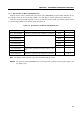
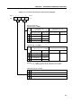
Figure 5-9. I/O Timing Chart of Digital I/O Ports (2/2)
(b) When data is input by a 2-machine cycle instruction
(c) When data is latched by a 1-machine cycle instruction
(d) When data is latched by a 2-machine cycle instruction
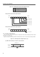
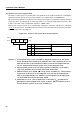
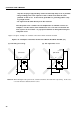
Figure 5-10. ON Timing Chart of Built-in Pull-Up Resistor Connected by Software
Instruction
execution
2 machine cycles
Input timing
Manipulation instruction
Instruction
execution
Pull-up resistor
specification
register
2 machine cycles
Built-in pull-up resistor setting instruction
Instruction
execution
Manipulation instruction
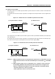
Output latch
(output pin)
301
ΦΦΦ
Instruction
execution
Output latch
(output pin)
01
ΦΦ
Manipulation instruction