
User manual


89
CHAPTER 5 PERIPHERAL HARDWARE FUNCTIONS
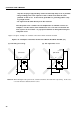
(3) System clock oscillator
The main system clock oscillator operates with a crystal resonator or ceramic resonator connected to the
X1 and X2 pins.
An external clock can also be input. Input the clock signal to the X1 pin and the reversed signal to the
X2 pin.
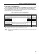
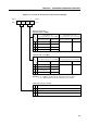
Figure 5-14. External Circuit for the Main System Clock Oscillator
(a) Crystal/ceramic oscillation (b) External clock
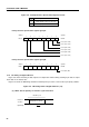
The subsystem clock oscillator operates with a crystal resonator (32.768 kHz standard) connected to the
XT1 and XT2 pins.
An external clock can also be input. Input the clock signal to the XT1 pin and leave the XT2 pin open.
The state of the XT1 pin is tested by bit 3 of the clock mode register (WM).
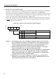
Figure 5-15. External Circuit for the Subsystem Clock Oscillator
(a) Crystal oscillation (b) External clock
Cautions 1. When the external clock is used as the main system clock or subsystem clock, the
STOP mode cannot be set. This is because the X1 pin is connected to V
SS
in the STOP
mode.
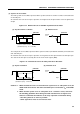
2. When the main system clock or subsystem clock oscillator is used, conform to
the following guidelines when wiring enclosed in broken lines of Figures 5-14
and 5-15 to eliminate the influence of the stray capacitance around the wiring.
• The wiring must be as short as possible.
• Other signal lines must not run in these areas.
X1
X2
External
clock
µPD750008
V
SS
X1
X2
Crystal or ceramic resonator
(Standard frequency: 6.0 or 4.19 MHz)
µPD750008
V
SS
XT1
XT2
Crystal
(Standard frequency: 32.768 kHz)
µPD750008
XT1
XT2
External
clock
µPD750008
Open