
User manual

166
µPD750008 USER'S MANUAL
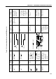
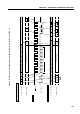
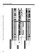
Table 5-10. Various Signals Used in the SBI Mode (2/2)
Synchronous clock for
outputting address/
command/data, ACK
signal, synchronous
BUSY signal, and so on.
Address/command/data
is output during first 8
clock cycles.
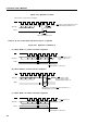
8-bit data transferred in
phase with SCK after
REL signal and CMD
signal output
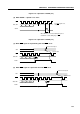
8-bit data transferred in
phase with SCK after
only CMD signal is
output, with REL signal
not being output
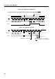
8-bit data transferred in
phase with SCK, with
neither REL signal nor
CMD signal being
output
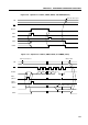
Serial clock
(SCK)
Address
(A7 - A0)
Command
(C7 - C0)
Data
(D7 - D0)
Output
device
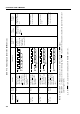
Definition
Execution of
instruction to
write data to SIO
when CSIE = 1
(Serial transfer
start request)
Note 2
Condition for
output
IRQCSI is set (on
rising edge of 9th
clock of
SCK)
Note 1
Flag
operation
Meaning
of signal
Timing of signal
output on serial data
bus
Address of slave
device on serial bus
Directions and
messages to slave
device
Numeric processed by
slave or master device
Signal name
Timing chart
Master
Master
Master
Master/
slave
SCK
SB0,
SB1
12 78910
SCK
SB0,
SB1
12 78
SCK
SB0,
SB1
12 78
CMDREL
CMD
SCK
SB0,
SB1
12 78
Notes 1. When WUP = 0, IRQCSI is always set on the ninth rising edge of the SCK signal.
When WUP = 1, IRQCSI is set on the ninth rising edge of SCK only when the received address matches the value held in the slave
address register (SVA).
2. In the BUSY state, data transfer is initiated after the READY state is set.