
User manual

173
CHAPTER 5 PERIPHERAL HARDWARE FUNCTIONS
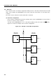
(10) Transfer start
Serial transfer is started by writing transfer data in shift register (SIO), provided that the following two
conditions are satisfied:
• The serial interface operation enable/disable bit (CSIE) is set to 1.
• The internal serial clock is not operating after 8-bit serial transfer, or SCK is high.
Cautions 1. Transfer cannot be started by setting CSIE to 1 after writing data to the shift
register.
2. The N-ch transistor needs to be turned off when data is received. So FFH must
be written to SIO beforehand. However, when the wake-up function specification
bit (WUP) is set to 1, the N-ch transistor is always off. So FFH need not be
written to SIO beforehand for reception.
3. If data is written to SIO when the slave is busy, the data is not lost. Transfer is
started when the busy state is released and input to SB0 (or SB1) goes high.
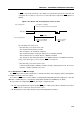
When eight bits have been transferred, serial transfer automatically terminates setting the interrupt request
flag (IRQCSI).
Example When RAM data specified by the HL register is transferred to SIO, from which data is loaded
into the accumulator at the same time, and serial transfer is started.
MOV XA,@HL ; Extracts transmit data from RAM
SEL MB15 ; or CLR1 MBE
XCH XA,SIO ; Exchanges transmit data with receive data and startstransfer
(11) Notes on the SBI mode
(a) Whether a slave is selected is determined by detecting a match for a slave address received after
bus release (in the state of RELD = 1).
An address match is detected usually using, an address match interrupt (IRQCSI) generated when
WUP is 1. So detect selection/nonselection state by slave address when WUP is set to 1.
(b) When determining whether a slave is selected without using an interrupt when WUP = 0, do not use
the address match detection method. Instead, use transfer of commands set in advance in a program.
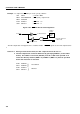
(c) When WUP is set to 1 during BUSY signal output, BUSY is not released. In the SBI mode, after release
of BUSY is directed, the BUSY signal is output until the next falling edge of the serial clock (SCK)
appears. Before setting WUP to 1, be sure to confirm that the SB0 (or SB1) pin is high after releasing
BUSY.