
User manual


218
µPD750008 USER'S MANUAL
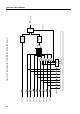
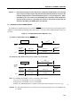
Figure 7-1. Standby Mode Release Operation (2/2)
(c) Release of the HALT mode by RESET signal
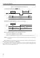
(d) Release of the HALT mode by the occurrence of an interrupt
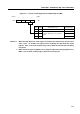
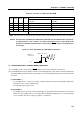
Note The following two wait times can be selected by a mask option:
2
17
/f
X
(21.8 ms at 6.00 MHz, 31.3 ms at 4.19 MHz)
2
15
/f
X
(5.46 ms at 6.00 MHz, 7.81 ms at 4.19 MHz)
However, the µPD75P0016 dose not have a mask option and its wait time is fixed to 2
15
/f
X
.
Remark The dashed line indicates the case where the interrupt request that releases the standby mode
is accepted.
When the STOP mode is released by the occurrence of an interrupt, a wait time is determined by the basic
interval timer mode register (BTM). (See Table 7-2.)
A time required for stable oscillation varies with the type of resonator used and the supply voltage at the
time of STOP mode release. Accordingly, a wait time is to be selected according to each application, and
BTM is to be set before the STOP mode is set.
*
HALT instruction
Standby
release
signal
Clock
HALT mode Operating mode
Oscillation
Operating mode
HALT instruction
RESET
signal
Clock
Operating
mode HALT mode
Operating
mode
Oscillation
Wait
Note