
User manual


51
CHAPTER 4 INTERNAL CPU FUNCTIONS
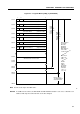
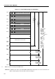
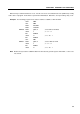
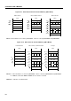
Figure 4-5. Program Memory Map (in µPD750008)
Note Can be used only in the MkII mode.
Remark In addition to the above, the BR PCDE and BR PCXA instructions can cause a branch to an
address with only the 8 low-order bits of the PC changed.
MBE RBE
76
0000H
MBE RBE
0002H
MBE RBE0004H
MBE RBE0006H
MBE RBE0008H
MBE RBE000AH
0020H
007FH
0080H
0
GETI instruction reference table
Branch address
specified in
BR !addr,
BR BCDE,
BR BCXA,
BRA !addr1
Note
,
CALL !addr
or CALLA !addr1
Note
Branch/call
address by
GETI
Relative
branch
address
specified in
BR $addr
instruction
(–15 to –1,
+2 to +16)
Entry
address
specified
in CALLF
!faddr
instruc-
tion
Branch
address
specified
in BRCB
!caddr
instruc-
tion
MBE RBE000CH
1FFFH
0800H
07FFH
Internal reset start address
Internal reset start address
INTBT/INT4 start address
INTBT/INT4 start address
INT0 start address
INT0 start address
INT1 start address
INT1 start address
INTCSI start address
INTCSI start address
INTT0 start address
INTT0 start address
INTT1 start address
INTT1 start address
(high-order 6 bits)
(low-order 8 bits)
(high-order 6 bits)
(low-order 8 bits)
(high-order 6 bits)
(low-order 8 bits)
(high-order 6 bits)
(low-order 8 bits)
(high-order 6 bits)
(low-order 8 bits)
(high-order 6 bits)
(low-order 8 bits)
(high-order 6 bits)
(low-order 8 bits)
0FFFH
1000H
Branch address
specified in BRCB
!caddr instruction
,
*