
user manual

CHAPTER 4 ND-45504 (E)
Page 134
Revision 2.0
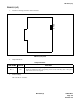
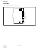
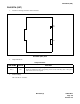
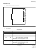
PN-2CSIA (CSI)
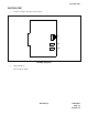
3. Switch Settings
The figure in the SWITCH NAME column and the position in in the SETTING POSITION col-
umn indicate the standard setting of the switch. When the switch is not set as shown by the figure and
, the setting of the switch varies with the system concerned.
Note:
Set the groove on the switch knob to the intended switch position.
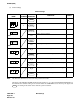
B10 Red
B channel status
ON : B0 channel of the No. 1 circuit is in use.
OFF : B0 channel of the No. 1 circuit is in idle.
Flash (60 IPM) : ZT is not connected to the No. 1 circuit.
ZT is in make-busy status.
B03 Red Not used (Flash[60 IMP])
B02 Red
B channel status
ON : B2 channel of the No. 0 circuit is in use.
OFF : B2 channel of the No. 0 circuit is in idle.
Flash (60 IPM) : ZT is not connected to the No. 0 circuit.
ZT is in make-busy status.
B01 Red
B channel status
ON : B1 channel of the No. 0 circuit is in use.
OFF : B1 channel of the No. 0 circuit is in idle.
Flash (60 IPM) : ZT is not connected to the No. 0 circuit.
ZT is in make-busy status.
B00 Red
B channel status
ON : B0 channel of the No. 0 circuit is in use.
OFF : B0 channel of the No. 0 circuit is in idle.
Flash (60 IPM) : ZT is not connected to the No. 0 circuit.
ZT is in make-busy status.
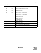
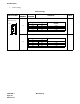
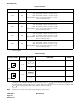
Switch Settings
SWITCH NAME
SWITCH
NUMBER
SETTING
POSITION
FUNCTION CHECK
DL0 (Rotary SW)
Note
0 ~ F
For normal operation
1 ~ F
Not used
DL1 (Rotary SW)
Note
0 ~ F
For normal operation
1 ~ F
Not used
Lamp Indications
LAMP NAME COLOR FUNCTION
0
0