
user manual

ND-45504 (E) CHAPTER 4
Page 23
Revision 2.0
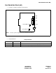
PN-BS00-A/PN-BS00-B (BS00)
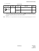
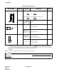
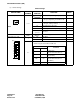
(3) Switch Settings
The figure in the SWITCH NAME column and the position in in the SETTING POSITION col-
umn indicate the standard setting of the switch. When the switch is not set as shown by the figure and
, the setting of the switch varies with the system concerned.
Note:
When the power is on, flip the MB switch to ON (UP position) before plugging/unplugging the circuit card.
Switch Settings
SWITCH NAME
SWITCH
NUMBER
SETTING
POSITION
FUNCTION CHECK
MB (Toggle SW)
Note
UP
For make-busy
For normal operation
ON
DOWN