
user manual


ND-45504 (E) CHAPTER 4
Addendum-002 Page 33
OCTOBER, 1998 Revision 2.2
PN-CP00-B/PN-CP00-C (MP)
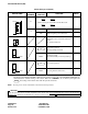
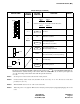
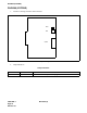
The figure in the SWITCH NAME column and the position in in the SETTING POSITION column
indicate the standard setting of the switch. When the switch is not set as shown by the figure and , the
setting of the switch varies with the system concerned.
Note: Set the groove on the switch to the desired switch position.
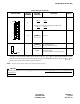
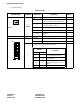
Switch Settings (Continued)
SWITCH NAME
SWITCH
NUMBER
SETTING
POSITION
FUNCTION CHECK
SW2 (Piano Key SW)
2, 3
• When using the PLO card (PN-CK00):
SW2-2
SW2-3
OFF ON
• When not using the internal PLO and the PLO card:
SW2-2
SW2-3
OFF OFF
4 ~ 8 Not used
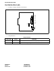
JP0 (Jumper pin)
For normal operation
Memory backup connected
DOWN
For factory testing
(Disconnect battery for memory backup.)
CAUTION
When the operating power is being supplied to this circuit card, do not plug/unplug this circuit card into/from its
mounting slot.
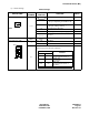
ON
OFF
8
7
6
5
4
3
2
1
OFF
Front
UP