PlasmaSync Plasma Monitor (Enhanced split screen Model) PlasmaSync 42XM5 PX-42XM5G PlasmaSync 50XM6 PX-50XM6G PlasmaSync 60XM5 PX-60XM5G User’s Manual Benutzerhandbuch Manuel d’utilisation Manual del Usuario Manuale dell’utente уководство пользователя Bruksanvisning Kullanım Kılavuzu Εγ ειρίδι ρήσης
User’s Manual (Enhanced split screen Model) ENGLISH
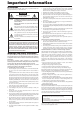
Important Information Precautions To avoid damage and prolong operating life: 1. Use only with 100 V to 240 V 50 Hz/60 Hz AC power supply. Continued operation at line voltages greater than 100 V to 240 V AC will shorten the life of the unit, and might even cause a fire hazard. 2. Handle the unit carefully when installing it and do not drop. 3. Set the unit away from heat, excessive dust, and direct sunlight. 4. Protect the inside of the unit from liquids and small metal objects.
WARNING This product equipped with a three-wire grounding (earthed) plug - a plug that has a third (grounding) pin. This plug only fits a grounding-type power outlet. If you are unable to insert the plug into an outlet, contact a licensed electrician to replace the outlet with a properly grounded one. Do not defeat the safety purpose of the grounding plug. NOTE: When you use an RGB cable (not supplied), use an RGB cable including the ferrite core (not supplied) on both ends of the cable.
Contents Important Information .................................. En-2 Contents ...................................................... En-4 Contents of the Package ........................................ En-4 Options .............................................................. En-4 Installation .................................................. En-5 Ventilation Requirements for enclosure mounting ...... En-5 Creating a video wall ........................................... En-6 Cable Management ........
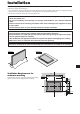
Installation You can attach your optional mounts or stand to the plasma monitor in one of the following two ways: * While it is upright. (See Drawing A) * As it is laid down with the screen face down (See Drawing B). Lay the protective sheet, which was wrapped around the monitor when it was packaged, beneath the screen surface so as not to scratch the screen face. * Do not touch or hold the screen face when carrying the unit. • This device cannot be installed on its own.
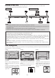
Creating a video wall With built-in matrix display capability, you can create a (2⳯2, 3⳯3, 4⳯4, 5⳯5, 5⳯1, 1⳯5) video wall. • Connect signal cables and remote cables as shown below.
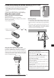
Caution when placing the plasma monitor in portrait mode OPTION1 MENU/ ENTER VOLUME DOWN UP LEFT/INPUT SELECT /EXIT 90° RIGHT/+ • Use the optional mount. Contact your store to purchase before installing. • Rotate 90° clockwise as seen from the front when installing. • After installing, make sure the NEC logo is located at the left hand side of the screen when facing the plasma from the front. • Be sure to set “OSM ANGLE” to “V” when using. * Failure to heed the above cautions may lead to malfunction.
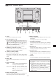
Part Names and Function Front View MENU/ ENTER MENU/ENTER 7 VOLUME DOWN UP LEFT/- RIGHT/+ INPUT SELECT / EXIT VOLUME DOWN UP LEFT/ - 6 RIGHT/+ INPUT SELECT /EXIT 5 4 q Power Turns the monitor’s power on and off. 1 3 2 t LEFT/– and RIGHT/+ Functions as the CURSOR ( / ) buttons and used to adjust the picture parameters in the On-Screen Menu (OSM) mode. w Remote sensor window Receives the signals from the remote control. e POWER/STANDBY indicator When the power is on .....................
Rear View/ Terminal Board 42XM5 L VIDEO 2 AUDIO 2 L/R R/Cr/Pr RGB2 / DVD2 / HD2 G/Y B/Cb/Pb HD VD RGB 1 (IN/OUT) AUDIO 3 L/R RGB 3 DV I RGB2 / DVD2 / HD2 RGB 1 R EXTERNAL CONTROL REMOTE IN OUT Y Cb/Pb L (MONO) G/Y B/Cb/Pb HD VD RGB 3 EXTERNAL CONTROL DV I ( Digital RGB ) (IN/OUT) Cr/Pr L (MONO) E AUDIO 3 REMOTE R R/Cr/Pr C DVD1 / HD1 Cb/Pb Cr/Pr A AUDIO 2 DVD1 / HD1 AUDIO 1 R 1 (IN/OUT) 3 Y D B VIDEO AUDIO 1 L/R L F G IN OUT (MONO) H I J K H RGB3 (DVI 24
Rear View/ Terminal Board 50XM6 L VIDEO 2 DVD1 / HD1 Cb/Pb Cr/Pr AUDIO 2 L/R R/Cr/Pr RGB2 / DVD2 / HD2 G/Y B/Cb/Pb HD VD RGB 1 (IN/OUT) AUDIO 3 L/R RGB 3 DV I EXTERNAL CONTROL REMOTE IN OUT A AUDIO 2 DVD1 / HD1 AUDIO 1 R RGB2 / DVD2 / HD2 Cb/Pb G/Y B/Cb/Pb HD VD L (MONO) E RGB 3 EXTERNAL CONTROL DV I ( Digital RGB ) (IN/OUT) Cr/Pr L (MONO) AUDIO 3 REMOTE R R/Cr/Pr Y 3 RGB 1 R 1 (IN/OUT) C Y D B VIDEO AUDIO 1 L/R L F G IN OUT (MONO) H I J K H RGB3 (DVI 2
Rear View/ Terminal Board 60XM5 L VIDEO AUDIO 1 L/R B VIDEO 2 AUDIO 2 L/R R/Cr/Pr RGB2 / DVD2 / HD2 G/Y B/Cb/Pb HD VD RGB 1 (IN/OUT) AUDIO 3 L/R RGB 3 DV I Y Cb/Pb RGB2 / DVD2 / HD2 B/Cb/Pb RGB 1 HD AUDIO 3 VD OUT RGB 3 EXTERNAL CONTROL DV I ( Digital RGB ) (IN/OUT) L (MONO) E REMOTE IN REMOTE R G/Y Cr/Pr L (MONO) EXTERNAL CONTROL A R R/Cr/Pr C DVD1 / HD1 Cb/Pb Cr/Pr D AUDIO 2 DVD1 / HD1 AUDIO 1 R 1 (IN/OUT) 3 Y L F G IN OUT (MONO) H I J K H RGB3 (DVI 24pi
u EXIT Press this button to exit the OSM controls in the main menu. Press this button during the display of the sub menu to return to the previous menu. Remote Control i POINTER Press this button to display the pointer. o ZOOM (+ /–) Enlarges or reduces the image. !0 VOLUME (+ /–) Adjusts the audio volume. !1 MUTE Mutes the audio. !2 WIDE Press this button to select and switch the screen sizes. WIDE button is not active for all signals. !3 DISPLAY Displays the source settings on the screen.
Basic Operations POWER OFF TIMER To turn the unit ON and OFF: 1. Plug the power cord into an active AC power outlet. 2. Press the Power button (on the unit). The monitor’s POWER/STANDBY indicator turns red and the standby mode is set. 3. Press the POWER ON button (on the remote control) to turn on the unit. The monitor’s POWER/STANDBY indicator will light up (green) when the unit is on. 4. Press the POWER STANDBY button (on the remote control) or the Power button (on the unit) to turn off the unit.
WIDE Operations Wide Screen Operation (manual) 2.35:1 size screen With this function, you can select one of seven screen sizes. When viewing videos or digital video discs 1. Press the WIDE button on the remote control. 2. Within 3 seconds ... Press the WIDE button again. The screen size switches as follows: → NORMAL → FULL → STADIUM → ZOOM → 2.35:1 → 14:9 → UNDERSCAN When a 720P or 1080I signal is input: FULL ↔ 2.
Wide Screen Operation with Computer Signals FULL size screen Switch to the wide screen mode to expand the 4 : 3 image to fill the entire screen. 1. Press the WIDE button on the remote control. 2. Within 3 seconds ... Press the WIDE button again. The screen size switches as follows: The image is expanded in the horizontal and vertical direction. → NORMAL → FULL → ZOOM ZOOM size screen When displaying enhanced split screen: NORMAL ↔ FULL NORMAL size screen (4:3 or SXGA 5:4) When wide signals are input.
SPLIT SCREEN Operations Showing a couple of pictures on the screen at the same time Operations in the Side-by-side mode To change the picture size, press the cursor button. * There may be some RGB-input signals that may not be displayed as not all signals are supported. 1. Press the button to select a screen mode from among single mode, side-by-side, and picture-in-picture.
Operations in the Picture-in-picture mode Selecting the input signals to be displayed 1. Press the SELECT/FREEZE button to make the desired picture active. 2. Press the RGB/PC, VIDEO, or DVD/HD button. Each press of the button changes the selection of the input signal. The INPUT SELECT button on the monitor can also be used to change the selection. To move the position of the sub screen, press the cursor or button.
OSM(On Screen Menu) Controls Menu Operations Note: The main menu disappears by pressing the EXIT button. The OSM window is displayed with respect to the screen as shown on the diagram. Information Advanced menu mode When “ADVANCED OSM” is set to “ON” in the main menu (1/2), full menu items will be shown. * Depending on the screen’s mode, the OSM may be displayed differently. In the explanation, the OSM section is shown close up.
Menu Tree :Shaded areas indicate the default value. ←→ : Press the or button to adjust. :Menu items in a ruled box are available when the ADVANCED OSM is set to ON. Main menu Sub menu Sub menu 2 PICTURE CONTRAST BRIGHTNESS SHARPNESS COLOR TINT PICTURE MODE NR COLOR TEMP. WHITE BALANCE ←→ 0←52→72 ←→ 0←32→64 ←→ 0←16→32 ←→ 0←32→64 R←→G 0←32→64 BRIGHT/NORMAL/THEAT.1/THEAT.
Main menu Sub menu Sub menu 2 OPTION2 PWR. MGT.
Picture Settings Menu Information Types of picture modes THEAT. 1, 2: Set this mode when watching video in a dark room. This mode provides darker, finer pictures, like the screen in movie theaters. For a darker image, select THEAT. 2. NORMAL: Set this mode when watching video in a bright room. BRIGHT: This mode provides brighter pictures than NORMAL. This mode provides dynamic pictures with distinct differences between light and dark sections.
Adjusting the color to the desired level Use this procedure to adjust the white balance for each color temperature to achieve the desired color quality. Example: Adjusting the “GAIN RED” of “HIGH” color temperature Set “ADVANCED OSM” to “ON” in the MAIN MENU. On “COLOR TEMP.” of “PICTURE” menu, select “HIGH”, then press the MENU/ENTER button. The “WHITE BALANCE” screen appears. On “GAIN RED”, adjust the white balance. WHITE BALANCE COLOR TEMP.
Audio Settings Menu IMAGE ADJUST ASPECT MODE : NORMAL V-POSITION H-POSITION V-HEIGHT H-WIDTH AUTO PICTURE : OFF FINE PICTURE PICTURE ADJ. UNDERSCAN : OFF EXIT RETURN SEL. ADJ. Adjusting the treble, bass and left/right balance and audio input select The treble, bass and left/right balance can be adjusted to suit your tastes. Example: Adjusting the bass AUDIO SEL. L : : : ADJ.
Option1 Settings Menu Setting the BNC input connector type Select whether to set the input of the 5 BNC connectors to RGB, Component or SCART1,2. Example: Set the “BNC INPUT” mode to “COMP.” Setting the on-screen menu This sets the position of the menu, the display format (horizontal or vertical) etc. Example: Turning the DISPLAY OSM off On “BNC INPUT” of “OPTION1” menu, select “COMP.”. On “OPTION1” menu, select “OSM”, then press the MENU/ ENTER button. The “OSM” menu appears.
Setting a computer image to the correct RGB select screen With the computer image, select the RGB Select mode for a moving image such as (video) mode, wide mode or digital broadcast. Example: Setting the “RGB SELECT” mode to “852⳯480 ” Setting the Input Skip When this is ON, signals which are not present will be skipped over and only pictures whose signals are being transmitted will be displayed. This setting is valid only for the INPUT SELECT button on the unit.
Option2 Settings Menu Setting the picture to suit the movie The film image is automatically discriminated and projected in an image mode suited to the picture. [NTSC, PAL, PAL60, 480I (60 Hz), 525I (60 Hz), 576I (50 Hz), 625I (50 Hz), 1035I (60 Hz), 1080I (60 Hz) only] Example: Setting the “CINEMA MODE” to “OFF” Set “ADVANCED OSM” to “ON” in the MAIN MENU.
ORBITER Use this to set the picture shift. Example: Setting “ORBITER” to “AUTO2” INVERSE Use this to set the inverse mode or to display a white screen. Example: Setting “INVERSE” to “WHITE” On “ORBITER” of “LONG LIFE” menu, select “AUTO2”. On “INVERSE” of “LONG LIFE” menu, select “WHITE”. LONG LIFE PLE : AUTO ORBITER : AUTO2 INVERSE : OFF SCREEN WIPER : OFF SOFT FOCUS : OFF SEL. ADJ. LONG LIFE PLE : AUTO ORBITER : AUTO1 INVERSE : WHITE SCREEN WIPER : OFF SOFT FOCUS : OFF EXIT RETURN SEL.
SCREEN WIPER When this is set to ON, a white vertical bar moves repeatedly from the left and of the screen to the right end at a constant speed. Example: Setting “SCREEN WIPER” to “ON” SOFT FOCUS Reduces edges and softens the image. Example: Setting “SOFT FOCUS” to “2” On “SOFT FOCUS” of “LONG LIFE” menu, select “2”. LONG LIFE PLE : AUTO ORBITER : AUTO1 INVERSE : OFF SCREEN WIPER : OFF SOFT FOCUS : 2 On “SCREEN WIPER” of “LONG LIFE” menu, select “ON”.
Option3 Settings Menu Setting the picture size for RGB input signals Use this procedure to switch the setting to “ON” or “OFF”. * This function is available only for 50 and 60 inch types. Example: Setting the “PICTURE SIZE” mode to “OFF” Set “ADVANCED OSM” to “ON” in the MAIN MENU. Using the timer This function sets the day of the week and time.
PROGRAM TIMER This sets the day and time at which the power will be switched ON/OFF as well as the input mode. Example 1: Setting so that the power will be switched on at 8:30 A.M., Monday, displaying RGB2 source, and switched off at 10:30 A.M. On “TIMER” menu, select “PROGRAM”, then press the MENU/ENTER button. The “PROGRAM TIMER” screen appears. Adjust the items. Use the ▲▼ and 䊴 䊳 buttons to move the cursor. Each mode switches each time the ZOOM Ⳮ/ⳮ button is pressed.
Setting the power on mode This function sets the input mode and the sound volume at the time the power is switched on. Example: Setting the input mode to “VIDEO2” The “REPEAT TIMER” screen appears. Adjust the items. Use the 䊴 and 䊳 buttons to select “SINGLE”. Use the ▲ and ▼ buttons to select the item, then press the 䊴 and 䊳 buttons to set. REPEAT REPEAT TIMER 1 WORK TIME INPUT MODE 2 WORK TIME INPUT MODE SEL. On “OPTION3 ” menu, select “PWR.ON MODE ”, then press the MENU/ENTER button. The “PWR.
Enabling/disabling remote control wireless transmission This function enables/disables remote control wireless transmission. Example: Setting “OFF” • Press and hold the POWER ON button, and release the button when the indication saying that the code is set is displayed. Or, press and hold the POWER STANDBY button, and release the button when the power is turned off. Information 䡵 REMOTE ID setting ALL: The remote code is not set. 1 to 4: The specified remote code is applied.
Video Wall setting Use this feature to configure a (2⳯2, 3⳯3, 4⳯4, 5⳯5, 5⳯1, 1⳯5) video wall. On “OPTION3” menu, select “VIDEO WALL”, then press the MENU/ENTER button. The “VIDEO WALL” screen appears. Information 䡵 VIDEO WALL POSITION settings 1 Screen: There is no need to set POSITION. 2⳯2 Screens 3⳯3 Screens NO. 1 NO. 2 NO. 4 NO. 3 VIDEO WALL : OFF DIVIDER POSITION DISP. MODE AUTO ID IMAGE ADJUST P. ON DELAY PLE LINK SEL. ADJ.
control the No.1 monitor will turn on and the others will be turned on one by one automatically. * From the second monitor onward, neither the POWER button on the unit nor the POWER ON button on the remote control works. However, by pressing and holding the POWER ON button for more than 3 seconds, the monitor will be turned on. OFF: Turns on the main power of all displays at the same time. (Only for 4⳯4 and 5⳯5 video wall modes) MODE1: Turns on the main power of each display delayed.
Option4 Settings Menu S BY S: Will show the entire image on the sub screen of side-by-side mode. BTM LFT~TOP LFT: Will show the entire image on the sub screen of picture-in-picture mode. Set “ADVANCED OSM” to “ON” in the MAIN MENU. Removing the sub screen area when there is no input signal detected for the sub picture This function automatically removes the black frame of the sub screen when there is no sub screen input signal.
Side-by-Side RGB1 RGB1 RGB1 On “TEXT INSERT” of “OPTION4” menu, select “BOTTOM-3”, then press the MENU/ENTER button. The “TEXT INSERT” screen appears. Adjust the items. SELECT/ FREEZE button SELECT/ FREEZE button S BY S1 Displaying the information as a text Example: Setting “TEXT INSERT” to “BOTTOM-3”, “INPUT” to “RGB1”, “SUB. P DETECT” to “AUTO”, “PIC. RATE” to “100%” and “DISPLAY” to “NORMAL” Picture-in-Picture RGB1 RGB1 TEXT INSERT INPUT : RGB1 SUB. P DETECT : AUTO PIC.
Advanced OSM Settings Menu Color System Settings Menu Setting the menu mode This allows you to access the complete menu. When P. ON DELAY or PLE LINK is ON, this won’t be turned OFF. Example: Setting “ON” Setting the video signal format Use these operations to set the color systems of composite video signals or Y/C input signals. Example: Setting the color system to “3.58 NTSC” On the MAIN MENU, select “COLOR SYSTEM”, then press the MENU/ENTER button. The “COLOR SYSTEM” screen appears.
External Control Pin Assignments Application mini D-Sub 15-pin connector (Analog) These specifications cover the communications control of the plasma monitor by external equipment. RGB 1 Connections 5 4 3 2 1 10 9 8 7 6 15 14 13 12 11 Connections are made as described below. External equipment e.g., Personal computer Pin No. 1 2 3 4 5 6 7 8 9 10 11 12 13 14 15 Display Connector on the plasma monitor side: EXTERNAL CONTROL connector. Use a crossed (reverse) cable.
Connection with STB 1/8 Stereo Mini Jack (not supplied) for REMOTE IN/OUT Following is the connection example of STB (Set-top Box) using the REMOTE IN/OUT connectors of the plasma monitor. Consult your dealer about the actual connection and operation. Plasma monitor REMOTE IN * Connection Example • STB has the REMOTE IN connector. • The pin assignment of the REMOTE IN connector of STB is same as that of 1/8 stereo mini cable connected to the REMOTE OUT connector (En-39).
Troubleshooting If the picture quality is poor or there is some other problem, check the adjustments, operations, etc., before requesting service. Symptom The unit emits a crackling sound. Picture is disturbed. Sound is noisy. Remote control operates erroneously. The remote control does not work. Monitor’s power does not turn on when the remote control’s power button is pressed.
Table of Signals Supported Supported resolution (42XM5) • When the screen mode is NORMAL, each signal is converted to a 768 dots⳯768 lines signal. (Except for *3) • When the screen mode is FULL, each signal is converted to a 1024 dots⳯768 lines signal.
Model Dots ⳯ lines Signal Type Work Station 1280⳯1024 (EWS4800) Work Station (HP) 1280⳯1024 1152⳯900 Work Station (SUN) Work Station (SGI) 1280⳯1024 1024⳯768 1280⳯1024 IDC-3000G PAL625P NTSC525P 768⳯576 640⳯480 Sync Polarity Horizontal Vertical frequency frequency Horizontal Vertical (kHz) (Hz) 64.6 60.0 NEG NEG 75.1 71.2 NEG NEG 78.1 72.0 –– –– 61.8 66.0 C Sync C Sync 71.7 76.0 C Sync C Sync 81.1 76.1 C Sync C Sync 49.7 60.0 –– –– 63.9 60.0 –– –– 50.0 59.9 31.4 31.
Supported resolution (50XM6/60XM5) • When the screen mode is NORMAL, each signal is converted to a 1024 dots⳯768 lines signal. (Except for *2, 3) • When the screen mode is TRUE, the picture is displayed in the original resolution. • When the screen mode is FULL, each signal is converted to a 1365 dots⳯768 lines signal.
Dots ⳯ lines Model Signal Type Work Station 1280⳯1024 (EWS4800) Work Station (HP) 1280⳯1024 1152⳯900 Work Station (SUN) Work Station (SGI) 1280⳯1024 1024⳯768 1280⳯1024 IDC-3000G PAL625P NTSC525P 768⳯576 640⳯480 *1 *2 *3 *4 *5 *6 *7 *8 *9 Sync Polarity Horizontal Vertical frequency frequency Horizontal Vertical (kHz) (Hz) 64.6 60.0 NEG NEG 75.1 71.2 NEG NEG 78.1 72.0 –– –– 61.8 66.0 C Sync C Sync 71.7 76.0 C Sync C Sync 81.1 76.1 C Sync C Sync 49.7 60.0 –– –– 63.9 60.0 –– –– 50.0 59.9 31.4 31.
Specifications 䡵 42XM5 Signals Synchronization Range Input Signals 40.4 (1.59") 1022 (40.2") 57.6 (2.31") 921.6 (36.3") Horizontal : 15.5 kHz to 110.0 kHz (automatic : step scan) Vertical : 50.0 Hz to 120.0 Hz (automatic : step scan) RGB, NTSC (3.58/4.43), PAL (B,G,M,N), PAL60, SECAM, HD*1 , DVD*1 , DTV*1 610 (24") Aspect Ratio Resolution Pixel Pitch 921.6 mm(H)⳯515.3 mm(V) 36.3 inches(H)⳯20.3 inches(V) diagonal 42 inches 16 : 9 1024 pixels(H)⳯768 pixels(V) 0.9 mm(H)⳯0.671 mm(V) 0.036 inches(H)⳯0.
Specifications 䡵 50XM6 Signals Synchronization Range Input Signals 38 (1.5") 1222 (48.1") 61 (2.4") 1104 (43.4") Horizontal : 15.5 kHz to 110.0 kHz (automatic : step scan) Vertical : 50.0 Hz to 120.0 Hz (automatic : step scan) RGB, NTSC (3.58/4.43), PAL (B,G,M,N), PAL60, SECAM, HD*1 , DVD*1 , DTV*1 736 (29") Aspect Ratio Resolution Pixel Pitch 1104 mm(H)⳯621 mm(V) 43.4 inches(H)⳯24.4 inches(V) diagonal 50 inches 16 : 9 1365 pixels(H)⳯768 pixels(V) 0.81 mm(H)⳯0.81 mm(V) 0.032 inches(H)⳯0.
Specifications 䡵 60XM5 Signals Synchronization Range Input Signals 45 (1.8") 1470 (57.9") 77 (3.0") 1319 (51.9") Horizontal : 15.5 kHz to 110.0 kHz (automatic : step scan) Vertical : 50.0 Hz to 120.0 Hz (automatic : step scan) RGB, NTSC (3.58/4.43), PAL (B,G,M,N), PAL60, SECAM, HD*1 , DVD*1 , DTV*1 880 (34.7") Aspect Ratio Resolution Pixel Pitch 1319 mm(H)⳯742 mm(V) 51.9 inches(H)⳯29.2 inches(V) diagonal 60 inches 16 : 9 1365 pixels(H)⳯768 pixels(V) 0.97 mm(H)⳯0.97 mm(V) 0.038 inches(H)⳯0.