
user manual

ND-70185 (E) CHAPTER 6
Page 137
Revision 3.0
POST INSTALLATION TEST
Repair Procedure When LED Indicates Abnormality
2.3 Test Procedure
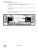
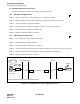
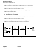
STEP 1: Set the MODE switch to 9 (Fusion Link Test) from 8 (standard setting) on the FCH card and initialize
the circuit card by turning the MB switch ON→OFF
Figure 6-5 How to Set the Fusion Link Test Mode
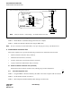
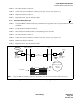
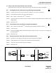
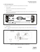
STEP 2: Select an appropriate loopback point by setting the switch (SW01/SW13B).
Figure 6-6 Loopback Point Designation
STEP 3: When the LYR LED flashes at 60-INT, the loopback in the block specified in Step 2 is OK.
8
4
C
0
2
6
A
E
.
.
8: standard setting
9: Fusion Link Test Mode
FCH card
FCH
DTI
MB
Front View
Front View
Mode:
8 9
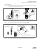
(1) Change the mode switch (8 9).
(i) UP
(ii) DOWN
Anti-static Kit
screw driver
PA-
FCHA
PA-
24DTR
Mode Switch
(2) Initialize the FCH card.
ATTENTION
Contents
Static Sensitive
Handling
Precautions Required
Note:
Be sure to initialize the FCH (PA-FCHA) card after changing the setting of the Mode Switch.
1 2 3 4
1
2
3
4
5
6
7
8
OFF
1
2
3
4
5
6
7
8
OFF
1
2
3
4
5
6
7
8
OFF
OPE
N-OPE
SW00
SW01
PCM
FRM
BER
RMT
AIS
BL23
MB
Payload
Line (External)
Internal
SW01/SW13B
Setting a Loopback point......
To set "Internal Loopback"
ATTENTION
Contents
Static Sensitive
Handling
Precautions Required
DTI (PA-24DTR)
ON
Anti-static Kit
Select a loopback point by setting the switch.
DTI