
user manual

CHAPTER 6 ND-70185 (E)
Page 138
Revision 3.0
POST INSTALLATION TEST
FCCS Network Connection Test
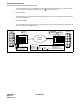
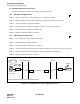
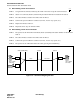
Figure 6-7 Fusion Link-Test Results
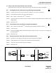
STEP 4: Return Mode to 8 (standard setting) when the test is complete.
STEP 5: Initialize the FCH (PA-FCHA) card using the MB switch.
Note:
Be sure to initialize the FCH (PA-FCHA) card, after changing the setting of the Mode Switch.
3. FCCS Network Connection Test
This section explains how to perform the following connection tests within the Fusion network:
• Station-to-Station Connection Test (via FCCS)
• ATTCON Connection Test (via FCCS)
• Line (LC, ELC, DLC card) Connection Test (via FCCS)
• 3-party Conference Trunk Function Test (via FCCS)
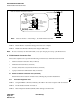
3.1 Station-to-Station Connection Test (via FCCS)
Perform the station-to-station connection test, following the procedure listed below.
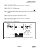
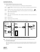
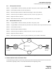
3.1.1 FCCS Call Origination Test
STEP 1: Using the MBCT command, make busy all trunks in the route except the trunk to be tested.
STEP 2: Lift the handset of STN A in Node A.
STEP 3: Dial a Telephone Number (STN B) which belongs to another node.
8
Mode
LYR
LB
LOAD
EST3
EST2
EST1
EST0
Remains ON
when available
for Ethernet
Remains ON
when ready to broadcast
data packets Note
Link is
established
Receive
Receive Polarity of
pair-wire is normal
Send
Flash
Front View
Make sure that the LYR LED flashes at 60-INT.
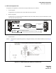
DTI
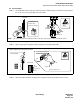
FCH
MNT
Front View
FCH (PA-FCHA) card
When the result of test
is OK, the LYR LED
flashes.
MB
Note:
When the FCH is a “Root Bridge”, the LOAD LED remains ON.
Check