
user manual

CHAPTER 7 ND-70185 (E)
Page 154
Revision 3.0
TROUBLESHOOTING
13-H/I/J Signaling Link Failure (Permanent)/(Temporary)/(Recovery)
6.1 Repair Procedure
• 13-H (Permanent)
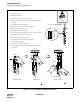
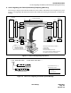
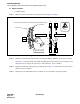
STEP 1: Make sure that the front cable is securely inserted. See Figure 7-10 below.
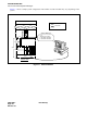
Figure 7-10 FCH-DTI Connection
STEP 2: Initialize the indicated FCH (PA-FCHA) card using the MB key. (MB key: Down
➔
Up
➔
Down)
See Figure 7-3. When the LED on the FCH card lights green and the related system messages are not
displayed anymore, monitor the system for a while. Otherwise, move to STEP 3.
STEP 3: Replace the FCH card, following the procedure listed in Figure 7-4. If the failure exists after card re-
placement, move to STEP 4.
STEP 4: Replace the front cable labeled 10AL (10) FLT CA, since the cable is suspected as faulty.
DTI
FCH(PA-FCHA)
DTI (PA-24DTR)
FCH
DTI
CN2
1
0
A
L
(
1
0
-
)
F
L
T
10AL(10)FLT CA
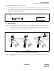
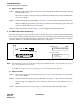
ATTENTION
Contents
Static Sensitive
Handling
Precautions Required
10AL(10)FLT CA
DTI
FCH
LED
MB
FCH
DTI
Firmly insert the connector on the front edge of the indicated FCH card.
indicated FCH card
FRONT VIEW