
user manual


ND-70185 (E) CHAPTER 3
Page 23
Revision 3.0
SYSTEM CONFIGURATION
System Considerations
Example: 2
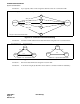
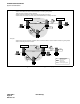
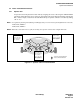
When both FCCS and CCIS links are established between two nodes
Figure 3-15 Centralized Management Report-Fusion (Example 2)
Node A/B/C:Refer to Example 1 on the previous page.
Node D: When Point Code of Node C (12) is assigned to ASYD, SYS 1, Indexes 184 and 185, System mes-
sages are sent to Node C using CCIS. When this system data is not assigned (0) and Fusion Point
Code of Node C (3) is assigned to ASYDL, SYS 1, Index 532, system messages are sent to Node C
using FCCS.
Centralized MAT
Center Node: Node C
Fusion
13-H
1. xxxx xxxx 0010 1222
4. x0010 1110 10110 1FFF
7. E23C CAAB12 000 0000
NEC
PC=10 FPC=4
PC=11
FPC=2
PC=12
FPC=3
Node B Node C
Node A Node D
CCIS
FCCS
FCCS
CCIS