ND-20292 APRIL, 1990 CHAPTER 1 SYSTEM DESCRIPTION TABLE SECTION OF CONTENTS DESCRIPTION 110 GENERAL 120 REGULATORY INFORMATION 120.1 120.2 120.3 120.4 120.5 120.6 130 . .. . . . . loo-1 . . +. . . . . . . loo-1 General Information ~:~.. . . . , . . _ , Company Notification . . .. . .. . . . Incidence of Harm . .. .. .. .. . . . . Emitted Radio Frequency Interference . .. . . .. . .. . . .. . .. . . Hearing Aid Compatibility . . . .. Service Requirements . . .. . .. . . . 100-l 100-2 100-2 .
ND-20292 CHAPTER APRIL, 1 1990 jack is provided by the telephone company. Jacks for this type of customer provided equipment will not be provided on party lines or coin lines. 120.4 EMITTED RADIO FREQUENCY INTERFERENCE In compliance with FCC Part 15 rules, the following statement The telephone company may make changes in its technical operations and procedures.
ND-20292 CHAPTER 1 APRIL, 1990 ecu CNF CPU co co1 Central Control Unit Conference Card (feature and control button as well) Central Processing Unit Central Office Central Office Line Interface -D- DID DIR DIT DLL DND DP DPA DSS DTA DTMF Direct Inward Dialing Directory Key Direct Inward Termination Dial Long Line Do Not Disturb Dial Pulse Dual Path Adaptor Direct Station Selection (also DSS/BLF) Data Terminal Adaptor Dual-Tone Multi-Frequency ECR ES1 ETE ETU EXT External Control Relay Card Electronic S
ND-20292 CHAPTER APRIL, 1 1990 part of the call record generated and can be up to thirteen digits long. A maximum of 500 recognizable codes are possible in a system (must be programmed by the Attendant). A CPU-EB3 (or higher revision level) is required to support this feature. ADD ON CONFERENCE provides the ability to converse with up to three additional parties in any combination of internal and/or outside lines. However, not more than two outside lines can be included.
ND-20292 CHAPTER APRIL, allows users to prompt the system to notify them when a busy extension becomes available. After calling a busy extension, set an Automatic Callback by dialing * 1 (as set in default). When both parties are idle, the system signals the originator first, and after answer, the called station. AUTOMATIC CALLBACK 1 1990 Electra Mark11 System when an outside party abandons the call (for this feature to function, the outside line must provide a timed disconnect signal).
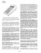
ND-20292 CHAPTER APRIL, 1 1990 The LCD indicates the number of Callback Messages (a maximum of five, including Message Waiting from an attendant and from the voice mail). The messages can be scanned one at a time. Each message display gives the time the message was left, identifies the caller, and provides a number to call. Callback Messages can be cleared while the terminal is idle, or will be automatically removed when the call is returned.
ND-20292 CHAPTER APRIL, station in the system or network. The ability to originate or receive Camp-On (a form of Transfer to busy extensions) is based on the Class of Service assignment of both stations. CENTREX RINGING provides two distinctive tone signals to identify internal CENTREX or PBX incoming calls from outside calls. Centrex Ringing requires the support of a CPU-EB3 (or higher revision level) ETU and a COT-EB ETU.
ND-20292 CHAPTER APRIL, 1 1990 Multiple Delay Announcement: First and Second are available with a CPU-EC4 (or higher revision level) ETU. DELAYED RINGING is provided to Multiline Terminals that are utilized as secondary answering positions. These terminals can be programmed to have their CO/PBX and/or extension lines ring on incoming calls, after a preprogrammed time interval. Separate Day & Night operations are possible. A CPU-EB3 (or higher revision level) ETU is required to support this feature.
ND-20292 CHAPTER APRIL, message mode, the associated green LED also provides the Attendant or unattended with the status of messages left for busy stations. Up to two DSSIBLF Consoles can be set to function with an Attendant Position. Up to three Attendant Positions can be provided with two DSSIBLF Consoles each. The totals are six DSSIBLF Consoles associated with four Attendant Positions. The number of CO AddOn Modules will also affect the six console maximum.
ND-20292 CHAPTER APRIL, 1 1990 Either method allows a Multiline Terminal user to initiate or receive a call (outside or internal) and converse without lifting the handset. GROUND START TRUNKS minimize the possibility of incoming and outgoing calls colliding on the same COI-E( ) ETU. This phenomenon (collision) is known as glare. In addition, Automatic Release is normally provided on Ground Start Trunks.
ND-20292 CHAPTER APRIL, INTERNAL ZONE PAGING (WITH MEET-ME) allows anyone (if allowed by Class of Service) within the Electra Mark11 System to generate a voice page via station speakers to a selected zone or to all zones of the installation. Up to three zones can be established by program assignment of stations into particular zones. Any station can release the page and talk privately to the originator of the page call by dialing the Meet-Me answer access code (set by default as 556).
ND-20292 CHAPTER APRIL, 1 1990 NIGHT CHIME(S) control is provided when the system is equipped with an ECR-E ETU. The ECR-E ETU contains ten relays. Three of these relays (one per tenant) can be programmed to provide closures when incoming CO/PBX calls are received in the Night Mode. The Night Chime feature is used after normal working hours to alert night personal of incoming outside calls. Locally provided external bells and/or amplifiers are controlled by the system.
ND-20292 CHAPTER 1 APRIL,1990 PROGRAMMING from Multiline Terminals of system functions is permitted locally at any of up to three ETE-16D-( 1 Multiline Terminal positions, or remotely at a PC, using an RAA-E Unit. Most changes to the system program can be entered while the system is in full operation. PUSHBUTTON DIAL - DTMF or DP- are provided on all Electra Mark11 Multiline Terminals for simplified and speedy calling.
ND-20292 CHAPTER APRIL, 3. 1 1990 ETE-16-2, dial access to 20 memories. 4. ETE-16D-( 1, direct selection the 20 memories. 5. ETE-16&l, 6. Single Line Telephone, STATION SMDR-E and/or dial access to direct selection to 110 memories. dial access to 20 memories. Each memory location has the capability of storing up to 16 digits (System Speed Dial numbers can be stored within a Station Speed Dial memory buffer of Multiline Terminals to increase this capacity).
ND-20292 CHAPTER 1 APRIL, 1990 Speed Dial memories, Night Pickup can be provided. Chimes, and Night Call TONE OVERRIDE allows station users to signal an in-use extension they want to talk to. Once alerted, a Multiline Terminal user can immediately answer the Override by depressing the Answer Key (placing the existing caller on Consultation Hold). Single Line Telephones can place their existing call on Exclusive Hold and answer the override call.
ND-20292 CHAPTER APRIL, 1 1990 Voice or Tone Signaling, Ringing Tone selection, Station Speed Dial memories, Background Music channel, Direct Station Selection assignment, and direct feature access assignment. The ETE-16K-1 Multiline Terminal provides the ability to program an eleven page directory, offering button access to memories (up to 110) used for Speed Dial, direct station selection, and direct feature access.
ND-20292 CHAPTER APRIL,1990 SECTION 150 LCD INDICATIONS DISPLAY LOCATION DEFINITION INITIALIZE All Stations System is Initializing NIGHT All Stations System in Night Mode EXT NUMBER? Originator Prompt in Call Pickun Directed VACANT Originator Speed Dial Memory Buffer Status Originator Prompt for Entering MUSIC NBR ? Originator Prompt for Station BGM Selection MUSIC 1 SET Originator Confirmation LK15 RECALL Originator Hold Recall Originator Recall for Unanswered (from 2011 ACCOUN
ND-20292 CHAPTER APRIL, 1 1990 LCD INDICATIONS DISPLAY LOCATION CO LINE DEFINITION Originator CONFERENCE PAUL.A (Continued) 03:46 On CO Line Key (Before Dialing) Conference Station Originating CO Conference Station During Internal Called/Calling 201 CONFERENCE Conference Party LK16 Receiving Station TR COCALL Elapsed Time Call During Conference Receiving CO Transfer LK16 NE1L.
ND-20292 CHAPTER APRIL, LCD INDICATIONS (Continued) LOCATION DISPLAY DEFINITION ICalculator 0.
ND-20292 CHAPTER APRIL, 1 1990 LCD INDICATIONS DISPLAY LOCATION MFR2 BUSYOUT DEFINITION Attendant DATA OFF MODEM DATA FROM (Continued) 3 Confirmation Calling/Called Receiving 123 Station of MFR Busied Out End of Data Communication Ready) Signal Going Off.
ND-20292 CHAPTER1 APRIL, 60.
ND-20292 CHAPTER APRIL, 1 1990 160.1 Codes Dialed While Receiving Dial Tone or Feature I FEATURE Set or Cancel Cancel from Attendant Station Not Locked Out&t Default Value from Attendant Night Mode Set or Cancel (Attendant Only) Call Pickup: Directed Group Trunk Access: Group 3 - 8 Group 2 Group 1 Forced/Verified Account Code EntryStation Lockout: 160.
ND-20292 CHAPTER APRIL, 1 1990 SECTION 170 EQUIPMENT IDENTIFICATION DESIGNATION MAXIMUM PER SYSTEM DESCRIPTION ESE-32B-1 CCU ESE-32E-1 CCU CCU BASE PSE-AD-1 PSU PSE-DD-1 PSU RSG-E UNIT RAA-E UNIT BASIC CENTRAL CONTROL UNIT.
ND-20292 CHAPTER1 APRIL,1990 170.1 GENERAL INFORMATION One set of Job Specifications and a wall mounting template are included with the ESE-32B-1 CCU. All optional equipment such as external amplifier, MOH source, BGM source, external speaker, modem, etc. must be locally provided. 170.2 1. EQUIPMENT ESE-32B-1 CCU DESCRIPTION This CCU is the basic Central Control Unit. This steel cabinet is designed to accommodate other expansion CCUs. A PSE-AD-1 or PSE-DD-1 power supply is required to provide service.
ND-20292 CHAPTER 1 APRIL, 1990 5. : PSE-DD-1 PSU This power supply accepts a DC input voltage of -48VDC and converts it to the necessary operating DC voltages of -5V, + 5V and -24V, required by a CCU. t or any RAA-E compatible unit, ie., NEC PC8300 Laptop Computer, NEC PC8231A Floppy Disk Drive, NEC Multispeed, Datavu’s SPARK laptop. 8. CPU-E ETU A CPU-E (or higher revision The PSU allows the system to be powered from a locally provided nominal -48VDC power source.
ND-20292 CHAPTER 1 APRIL, 1990 To connect MOH and BGM sources, the TSW-EB ETU houses audio digitizer circuits to change analog signals to digital signals. mix of Multiline Terminals, DSSIBLF E unit, or CO Add-On Modules. NOTE: It is recommended that the ESI-EA ETU be the only Multiline Terminal Interface card installed in the fourth CCU. The fourth CCU cannot support the additional features supported by the ESI-EB ETU. 12.
ND-20292 CHAPTER APRIL, A maximum of nineteen SLI-EA ETUs can be installed ~ per system. ; .z’ 20. SLI-EB ETU The SLI-EB ETU is a Single Line Telephone Interface Unit which includes the functions of the SLI-EA ETU and provides Message Wuiting indication to SLTs equipped with a Message Wuiting lamp. Each SLI-EB ETU contains serve up to four SLTs. four identical The SLI-EB ETU is required transfer of COs to SLTs. for use with power failure A maximum per system.
ND-29292 CHAPTER 1 APRIL, 1999 A maximum of one LCR-E ETU can system. Data input (programming) provided by an NEC PC8300 portable drive and floppy, NEC Powermate, or PC. be installed per to the LCR is computer, disk IBM compatible 27. ETE-6-C ) TEL The ETE-6-t 1 TEL is a fully modular, digital Multiline Terminal with six line keys, seven function keys and one message wait LED. Line keys can be assigned for outside lines, extension lines, DND (Do Not Disturb), S & R (Save and Repeat), and Pooled Lines.
ND-20292 CHAPTER APRIL, 33. EDE-30-( ) DSS/BLF 36. The EDE-30-( ) DSS/BLF is the Direct Station Selection/Busy Lamp Field console that is equipped with thirty three programmable non-locking buttons. thirty buttons are used to assign DSS or such features as Transfer, paging, Attendant Override, Night Mode and Message Waiting. Three buttons are for feature use only.
,- CHAPTER 2 HARDWARE INSTALLATION AtoZ KELLATRONICS, INC,
ND-20292 APRIL, 1990 CHAPTER 2 TABLE OF CONTENTS SECTION 210 220 220.1 220.2 220.3 220.4 220.5 220.6 220.7 220.8 220.9 220.10 220.11 220.12 220.13 220.14 220.15 220.16 220.17 220.18 220.19 220.20 220.21 230 230.1 230.2 230.3 230.4 230.5 230.6 230.7 230.8 240 240.1 240.2 240.3 240.4 240.5 240.6 240.7 240.8 DESCRIPTION GENERAL PAGE ............ 200-1 SECTION DESCRIPTION 250 POWER SUPPLY INSTALLATION SPECIFICATIONS General Information ............ Programming Station .. ., ........
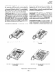
ND-20292 CHAPTER APRIL, 2 1990 Each interface and optional ETU contains a switch (SWl) to protect its circuitry from damage during insertion and removal while power is applied to the unit, make it a habit to ensure this switch is OFF. (See Figure 200-l) Insertion Front View Terminal or the RAA-E Unit. The fourth position becomes available when the RAA-E Unit is installed. The first two programming positions are system attendants and are fixed in system software. ,‘. $ ;: 220.
ND-20292 CHAPTER 2 APRIL, 1990 Line Telephones, traffic. Heavier MFR-EA ETUs be SLTs installed are Table 200-l SINGLE modem traffic installed low. Recommended pooling, and Voice Mail’ may require additional even though the amount of MFR-EA 4. CCUs, PSUs, and RSGs a. An ESE-32B-1 CCU is always required. b. ETU Quantities MFR.EA ETUs RECOMMENDED LINE TELEPHONES CONNECTED I 0 0 i l-20 1 I 21-40 2 41-60 3 61-76 I 4 I of interface I c.
ND-20292 CHAPTER APRIL, rr 2 1 1990 I LIUle: ETU Llvv-Y I. UIIIkJ~:L CIRCUITS PER ETU “L lvzqurl eu Lllbtx lixL;I: u 4. ” D MAXIMUM ETUs PER SYSTEM CALCULATION COI-E( ) 4 Divide the number of CO/PBX lines being used by 4. (Note 1) 10 (Note 7) ESI-EA/B 4 Divide the number of Multiline Terminals, CO Add-On Modules, and DSS/BLF Consoles being used by 4. (Note 2) 20 (Note 4) SLI-Em 4 Divide the number of Single Line Telephones and/or Modems being used by 4.
ND-20292 CHAPTER 2 APRIL, 1990 5. Optional Equipment Table 200-4 shows optional equipment that can be installed in Multiline Terminals. When a DPA-E Unit, DTA-E Unit, or both, are installed in a Multiline Terminal, the Terminal must be supported by an ESI-EB ETU. OPTIONAL 1. Provide a suitable cold water pipe ground in accordance with the operating telephone company procedures. 2.
ND-20292 CHAPTER 2 APRIL, 1990 220.7 ELECTRICAL NOISE GENERATORS Equipment such as welding machines, thyristor-driven power supplies, electric motors, etc., generate electrical noise. As a stored program unit, the Electra Mark11 System is vulnerable to this noise. When this type of machinery is present at an installation, the following precautionary steps are urged: 1. Locate the CCUs terminal equipment away from these machines. and cabling 2.
ND-20292 CHAPTER 2 APRIL, 1990 2. a. b. c. d. The central equipment of this system consists of up to four Central Control Units (CCUs). Basic CCU: 32 ports. Basic CCU + 1 Expansion CCU: 64 ports. Basic CCU + 2 Expansion CCUs: 96 ports. Basic CCU + 3 Expansion CCUs: 128 ports. 3. A maximum of two DSS/BLF Consoles and one CO Add-On Module can be equipped at any attendant position, provided the system maximum of six units is not exceeded. 4.
ND-20292 CHAPTER APRIL, 2 1990 ELECTRA MARK11 TERMINAL 2. ii: 2 F. g* h. si.
ND-20292 CHAPTER 2 APRIL, 1990 Table 200-8 Power DC VOLTAGE 1 Supply Outputs lt%EiKY -24V + 2V 1 4.5A -5V + 0.25V 1.2A +5V 8.OA k 0.25V I Table 200-9 Fuse Replacement FUSE # 1 SPECIFICATION PSE-AD-1 Fl 125V, 6.3A PSE-DD-1 -.. Fl 125V, 8.OA DC INPUT (-48V) Fl 25OV, 0.5A DC INPUT (-24V) UNIT RSGE 220.13 ENVIRONMENTAL 1. Temperature DIMENSIONS INPUT l/4” x 1 l/4” l/4” x 1 l/4” 1 13164” x 45164” (5mm x 20mm) b. Recommended 32.2” C) e.
ND-20292 CHAPTER 2 APRIL, 1990 TDM TDM TDM TDM 2.048 MHz 488.28 ns. 8 bit 125 ps. clock slot period data bus time frame 4. Telephones a. Multiline Terminal Voltage: Max. current: Maximum d. Rise time: and EDE-30-( 1 unit: -11 - -26 VDC 200 mA Acoustic characteristics meet Electronic Industry Association (EIA) standard proposal SP-1286 and standard EIA RS-470. b.
ND-20292 CHAPTER APRIL, 220.18 DIMENSIONS (Refer to AND WEIGHTS 7. Table 200-l 1) Table 200-l 1 ‘g;;;‘HF UNIT HE’;zyT WIDTH 6-1 DEPTH (mm) 14 314” (375) 25 9116” (640) 12 518” 11 13/16” (300) 25 9116” (640) 12 518” (320) (kg) ESE-32B-1 43 lbs. 302. (19.6) 26 Ibs. (11.8) PSE-AD-1 3 lbs. 1102. (1.7) 8(;&; 3 15/16” (100) 9 l/16” (230) PSE-DD-1 3 lbs. 1102. (1.7) 8(;3;;3. 3 15/16” (100) 9 1116” (230) 2 5132” (55) 9 l/16” (230) 3 15116” (100) 7 718” (200) 5 lbs. 502. (2.
ND-20292 CHAPTER 2 APRIL, 1990 3. Power Requirements The DTA-E Unit is provided with supply adaptor as an attachment. this AC/DC adaptor are as follows: NQTE: Other pins are not connected t . AC Input: DC Output: NomdAL VOLTAGE Figure 200-5 RS-232C Straight Cable Pin Connections an AC/DC power Specifications for 120V AC, 60 Hz, single phase DC VOLTAGE TOLERANCE +12v 11.4v f 0.3v 210 mA RS-2iz$eLine -12v 12.6V + 0.3V 8Od l?S-232C Line Drive +12v 12.4V & 0.3V 65m.
ND-20292 CHAPTER APRIL, 2 1990 Table ZOO-13 LED Flash Pattern LED CONDITION I FLASH PATTERNS I-Use Outside Extension Line * Microphone Speaker Conference m---m User Programming -----Red Broker’s Call Incoming call, Camn-On Override.
ND-20292 CHAPTER 2 APRIL, 1990 Table 200-14 LED DSS KEY (see Note 1) DSS/BLF Visual Indications: STATUS FLASH PATTERNS Station is idle or in the busy mode and its Primary Extension has an incoming call, call on hold, or recalling call. Station is off-hook on a call and its Primary Extension is idle or in the I-Use mode. ** Red Green Station is idle or in use and its Primary Extension is in use by another station * or off-line or station lockout.
ND-20292 CHAPTER APRIL, Table 200-15 DTA-E Unit / RS232C Configuration PIN # SIGNALFLOW 1 Connector Pin 230.3 l Limited space is available regardless of its suitability. 0 The available space may be adequate but may pose one or more environmental hazards. 0 The proposed location has limitations, such as, insufficient lighting, or the lack of a suitable ground, for grounding the CCUs. with the RS-232C interface. SITE 230.
ND-20292 CHAPTER APRIL, 2 1990 which could cause a hazard to personnel proper functioning of the equipment. or to the 66B50 66M50 TYPE TYPE TELCO RJ2lX D. Heat and humidity must be within the limits provided in Section 220.13 of this document. .-.: A’ E. Although its virtually noiseless operation allows a wide selection of installation sites, care should be taken that CCU(s) do not present a hazard to office traffic. For purposes of economy a central location to minimize cabling is often used. 230.
ND-20292 CHAPTER 2 APRIL, 1990 / J Connector and Por 4Relatior ab \ PIN KEY RUNNING CABLE TEL LEAD 7 FUNCTIONS BWIRE 4WIRE ECR SLT I VMI E&M TIE LINE Note 2 WI-I-BL BL-WI-I WI-I-OR ORWH GN RD BK YL TA RA TB RB T R PT PR 28 3 29 4 WI-I-GN GN-WI-I WH-BR BR-WI-I GN RD BK YL TA RA TB RB T R PT PR 30 5 31 6 WH-SL SL-WI-I RD-BL BL-RD GN RD BK YL PA RA TB RB ii PT PR 32 7 33 8 RD-OR OR-RD RD-GN GN-RD GN RD BK YL E TB RB z PT PR 34 9 35 10 RD-BR BR-RD RD-SL SL-RD GN RD BK YL TA It
ND-20292 CHAPTER APRIL, 2 1990 Refer to section 220.11 of this document for specifications. Refer to Table ZOO-16 for lead identifications, and Figure ZOO-8 for station modular jack (RJlJCI W) connection. For additional CO line connections to additional similar cross connections should be made. Since all of the SLTs must be equipped with DTMF dials, the outside lines must allow tone dialing if dialing during power failure is required.
ND-20292 CHAPTER APRIL, J8 (AC OUT) J7 J6 J5 (RSG) 2 1990 - J4 (DC IN) 0 o PSE-AD-1 RSG-E - Figure 200-10 c. Front View of ESE-32B-1 CCU Unscrew the two screws located on the top front of the CCU, then remove the top panel. Place the panel and screws aside for later reinstallation. D. Unscrew the two screws located on the bottom front of the CCU, then remove the base panel. Place the panel and screws aside for future reinstallation. E.
ND-20292 CHAPTER APRIL, N. 2 1990 Using the separately ordered CCU base panel; mount it to the wall just above the second ESE32E-1 CCU, ensuring that minimum space is between the base panel and the second CCU. Install the wall mounting metal brackets as shown in Figure 200-11, using the eight locally provided fasteners. Upper Wall Mount Bracket CCU Base Panel Figure 200-12 Wall Mounting ESE-32B-1 CCU The CCUs are designed to be wall mounted.
ND-20292 CHAPTER APRIL, Figure 200-13 Wall Mounting ANCHORS (7 13/l 6”) 200 MM *.-. (4) / -.-. Top Panel and Front Panel . ----@Q a&j ./.I’ *’.’ .-.- . -. .-.-.. @Q 4 ;;! ._ ~.~.~.~.~.~.~.~.~.~‘~.~ I’ H Q -.-.-* BOLT & WASHER CONCRETE OR WOOD WALL. Installing _.-._.-.-.-.-.-.-.-.-.-.. .-.-.-.-@,84 1.1’ .-.-.-.d. 8.’ /* /* *. -.-.-. I.#!9 J 0. .-._.-.-..m.-.-.
ND-20292 CHAPTER APRIL, 2 1990 Install the wall mounting metal brackets as shown in Figure 200-11, using the four locally provided fasteners. Using the open slots provided on the back panel of the CCU, mount the CCU to the knobs of the upper bracket and onto the base panel. Ensure the upper bracket knobs are fully seated within the open slots of the CCU. Tighten the screws from above the CCU to securely attach the CCU to the upper bracket knobs, install the two screws shown in Figure 200-12. I. 240.
ND-20292 CHAPTER 2 APRIL, 1990 provided Manual. in Section 430 of the Installation Service When the CPU-E( ) ETU is removed for long term storage, set the SW2 switch to OFF. This will prevent the battery from constantly discharging. The battery, when fully charged, will retain memory contents for approximately 7 days. Switch 1 (SW11 is the reset switch. When depressed, this momentary switch interrupts all service in progress causing a second initialization.
ND-20292 CHAPTER APRIL, 2 1990 Switch labeled MELODY (SW31 is used to select one of two melodies from the internal MOH music chip, mounted on the TSW-E ETU. VRl is used to adjust the volume of the melody provided by the melody chip. RCA hono plug EP provides External Pa e common audlb3 e and is used for connection of a local f y provided amplifier for external paging. RCA phono plug MOH is used for the connection external MOH source, ifneeded. The TSW-E ETU must be installed the ESE-32B-1 CCU.
\ ND-20292 CHAPTER APRIL, : When a loop start trunk is connected to a circuit, its associated switch must be set to the LP position. If a ground start trunk is connected, the switch must be set to the GD position. Switches designated SW301, SW302, SW401 and SW402 are four position dip switches used to select loss level for loop dial, DID, 2 and 4 wire E&M Tie lines. Loss levels can be adjusted for 0, 2, 4, 8, 12 or 16 db. (See Figure 200-21).
ND-20292 CHAPTER 2 APRIL, 1990 Transmit Receive 1 mON 2 aON 3 =ON 4 5 DON /6 mON 7 8 =ON Figure 200-22 All switches OFF = Switch 1 ON = Switch 2 ON = Switch 3 ON = Switch4ON= All 4 Switches ON= Switch 5 ON = Switch 6 ON= Switch 7 ON= Switch 8 ON = All 4 switches ON= mON mON Odb -2db -4db -8db -12db -16db -2db -4db -8db -12db -16db SW102, or SW202 pad switch settings on TLI-EB ETU Figure 200-23 ESI-E( ) ETU Busy Switch with LEDs SW102 (switches Channel 1.
ND-20292 CHAPTER APRIL, able 200-17 PORT ETU COI-E( ESI-E( SLI-E( & VMI-E MFR-EA az CNF-E ECR-E ) LED LED LED LED LED ) LED 1 LED2 LED3 LED4 LED 5 ) Interface ETU LED/Switch LED 101 201 301 401 1 - Busy 1 Busy2 Busy3 Busy4 Receiving Power 101 201 301 401 1 - Trunk Trunk Trunk Trunk Busy Selection Selection Selection Selection Out LED 101 - Busy 1 LED201 - Busy2 LED301 - Busy3 LED401 - Busy4 LED 1 - Receiving Power SW1 - Busy Out LED 1 - Receiving Power SW 1 - Busy Out LED 1 - Recei
ND-20292 CHAPTER APRIL, 2 1990 240.6 OPTIONAL A. CNF-E ETU INTERFACE The CNF-E ETU contains (LEDl). SW1 is used to busy out the ETU when the ETU is removed or inserted without powering down the CCU. ETUs a switch (SW11 and an LED SW1 is used to busy out the ETU when the ETU is removed or inserted without powering down the CCU. LED1 (Green) lit, receiving power. indicates the CNF-E ETU A maximum of four CNF-E ETUs can be installed system, into any interface slots. B.
ND-20292 CHAPTER APRIL, Mount the RS232C connector in one of the openings using screws and nuts locally provided. (See Figure 200-27.) DIP 1 El m m 48x100 24 11111 I 12 6 I 3 ON C. Connect a printer or other peripheral device to the RS232C connector mounted on the CCU in Step B. Secure the RS-232C male connector from the printer or other peripheral device with the screws provided with the device. D. Turn ON SW2 of the SMDR-E ETU.
ND-20292 CHAPTER APRIL, 2 1990 removed or inserted ecu. without powering down the Switch DIP1 (see Figure 200-30 and Figure 20031) is a 7 position dip switch which is used to select baud rates in the range of 150 - 9600 (4800 is the recommended setting). LED1 (Green) lit, indicates receiving power. 2. that the LCI+E ETU is Connection of LCR A. The LCR-E ETU must be installed into either OPT1 or OPT2 or any combination slot of any CCU.
ND-20292 CHAPTER APRIL, INCOMING CALLS TRANSFERRED Incoming Call Without 07/04/86 09:OOAM 00:15:32 CALLS an Account Code: 08-05 IC 120 Transferred Call Without ~~04&8E509:00AM : . Incoming Call With an Account 07104f86 09:OOAM 08-05 00:15:32 3 4L562 TL an Account 08-05 IT 1 Account Code: ?_u 2 1990 Code: IC 120 Code 14 characters) (Max.
ND-20292 CHAPTER 2 APRIL, 1990 LCR data input is done from an NEC PC8300 portable computer or, NEC Powermate, IBM AT/XT. 3. For LCR programming, refer Installation Service manual. POWER to Chapter 7 of the SECTION 250 SUPPLY INSTALLATION 250.
ND-20292 CHAPTER APRIL, .1 The voltages for each PSU can be checked individually by first turning the system AC switch ON and then the switch on each power supply ON. 250.2 PSE-DD-1 NOTE: Before proceeding to install the PSE-DD-1 PSUs, ensure theInput Line Cords are not connected to the locally provided -48VDC power source and the input power switches on each PSE-DD-1 PSU are in the OFF position. The input line cords for the PSE-DD-1 PSUS must be locally provided. GREEN PSU A.
ND-20292 CHAPTER 2 APRIL, 1990 SCREW TERMINAL IN THIRD BLOCK ON PSE-CID-1 ESE-32E-1 SCREW TERbIUiAL BLOCK ON PSE-DD-1 IN SECOND ESE32E-I I I V SCREWTERMINALBLOCKONPSE-Di-1 IN FIRST ESE92E.1 I I ov Figure 200-39 'SCREWTERMINAL BLOCKONPSE-DD-1 C RSG-E Unit If the adjacent CCU requires ringing signal, use the supplementary cable that is included in the RSG-E ETU packing box.
ND-20292 CHAPTER APRIL, Table 200-18 ANCILLARY DEVICES HFU-E DPA-E ADA-E DTA-E l C. Ancillary Device, dultiline ETU ETU ETU ETU 1 ETE-GD-( ) ETE-16-2 0 0 0 0 0 I ETE-16D-( ) 1 ETE-16K-1 0 . 0 8 0 0 0 0 0 = Compatible These optional devices are installed inside the access panel on the bottom of Multiline Terminals. A maximum of one unit of each type can be installed in each Multiline Terminal, except for ETE-8( ) or the ETE-16-2, which can only accept the ADA-E Unit.
ND-20292 CHAPTER APRIL. 2 1990 panel on the bottom of the Multiline refer to Figure 200-41. Terminal, B. Slide the directory out of the way. C. Insert a flat screwdriver blade into the notched opening (shown as Al and apply light upward pressure until the access panel is cleared of the front lip, at the same time apply pressure (towards you) at the rear of the pedestal (shown as B) until the access panel moves toward you. D. Remove the access panel and place it aside for later reinstallation. E.
ND-20292 CHAPTER APRIL, K. Secure the ADA-E Unit provided with the Unit. L. Replace the access panel by inserting 2 1990 the screw OR Continue to install the HFU-E Unit, DTA-E Unit, or the DPA-E Unit. 260.5 ADA-E INSTALLATION or ETE-16-2 MULTILINE into ETE-6-( TERMINALS ) A. Unplug the line cord at the RJlSC/W and the terminal, then turn the Multiline Terminal upside down (face down) and locate the access panel on the bottom of the Multiline Terminal, (refer to Figure 200-41.) B.
ND-20292 CHAPTER APRIL, 2 1990 Figure 200-44 Connection of DTE/DTA-E Unit Remove the access panel, save for possible future use. D. Before installing the DTA-E Unit, its switches should be set for the proper assignment. (Refer to Table 200-19). The DTA-E Unit contains a 7 position DIP switch designated SW1 a slide switch designated SW2, and an 8 position DIP switch designated SW3. Table 200-19 shows the assignments of these switches. E.
ND-20292 CHAPTER APRIL, 2 1990 receptacle, then connect the DC output cable of the AC/DC adaptor into the connector on the DTA-E Unit, as shown in Figure 200-44. 4. Connect one end of a locally provided RS232C straight cable to the RS-232C connector of the DTA-E Unit. Refer to Figure 200-44. 5. Secure the RS-232C connector with screws provided with the RS-232C cable. Refer to Figure 200-44. 6. Connect the other end of the RS232C cable to the DTE as described in the instructions provided with the DTE.
ND-20292 CHAPTER 2 APRIL, 1990 DTA-E Table. 200-12 \I *F Switch Assignment DTR ia to be provided by the data terminal /TSiswcedhigh. NOTE1 equipment PB kin *OFF (DIP WITCH) 4 SD 5 PB/ER 6 PIUPN DH/DS 7 * PB (Peripheral . .b.UW.. . . . . . . . . . . . ER (Peripheral ready) PR (Polarity ON *OFF’ *nN 1 equipment (DTE). indicator from modem) is forced hi h. NOTE 1 PB is to be arovided by the modem. NOTE 1 TD is forced high. TD is to be provided by the DTE.
ND-20292 CHAPTER APRIL, 2 1990 SECTION 270 OPTIONALEQUIPMENT CONNECTION 270.1 MUSIC ON HOLD Provision has been made to allow connection of a locally provided external music source to provide Music On Hold for held calls. Music source input is made using the phono jack MOH located on the TSW-E( ) ETU. For music source input level and impedance, refer to Section 220.20 of this document. NOTE: Figure ZOO-47 A.
ND-20292 CHAPTER APRIL, 2 1990 through EPC 3A and EPC 3B. A maximum of one ECR-E ETU can be installed in a system providing a total of three paging zones. Figure 200-50 I. “:
ND-20292 CHAPTER APRIL, NOTE: Diodes Dl -D3 or equivalent are lN4004 24 VOLT 2 1990 DC POWER * = Normal open contacts + = Normal closed contacts r-l SUPPLY EXTERNAL SWITCHING RELAYS .-EPC EPC 1A 1B RELAY I 1 i EPC EPC , EPC EPC 2A ZB I I I I RELAY 2 RELAY 3 I I I I I I 3A 3B I I I R3 ,, Phono Jack Figure 200-52 Connection of External continuous tone source for external tone ringing. The External tone can be set to any of four ring patterns.
ND-20292 CHAPTER APRIL, 2 1990 communication Equipment). mode. Relay contacts (armature) for relays 4, 5, and 6 can be found at the MDF ECR 4A/4B through ECR 6A/6B. Relay contacts (armature) 7,8,9, and 10 can be found on the ECR-E ETU Al/B1 through A4/B4 connections CN 1 and CN2. C. Connection information of the locally provided amplifier and speakers is provided in Figure 200-53. Audio output specifications can be found in Section 220.20 of this document. with outside DTE (Data Terminal ,.
ND-20292 CHAPTER APRIL, RS-232C MALE CONNECTOR RS-232C MALE CONNECTOR 7 . SC SG . 7 22 . RI RI l 22 11 0 CABLE LENGTH: CABLE TYPE: 2 1990 11 50 feet (15 m) max. Twisted pair shielded RS-232C cross cable with RS-232C male connectors on both ends. NOTE: The special null modem cable has pin 22 crossed to pin 11. Figure 20054 Wiring Connections (Rev. 1 only) Unit. the AC/DC adaptor into shown in Figure 200-44. Dl.
ND-20292 CHAPTER APRIL, 2 1990 RS-232C MALE CONNECTOR TO MODEM Q RS-232C MALE CONNECTOR 7 SG . . 2 TXD . TXD 3 Rx5 *-: RXD 4 RTS l . 4 RTS 5 CTS . . 5 CTS TO DTA-E 6 DSR . l 6 DSR UNIT 8 DCD . . 8 DCD 20 DTR . 20 DTR 11 PB . - NOTE 1: Switch settings on DTA-E Unit are as MBlD2, LK3 must be OFF. Wiring Connections of RS-232C Null Modem Cable for Connecting (Rev. 2 or higher) Unit. EIA PIN NO.
ND-20292 CHAPTER APRIL, J. Connect power to the modem and turn on the power switch on the modem (ifone is provided). K. Repeat the installation steps for all modems (a maximum of four modems) to be installed for use in modem pooling. L. 2 1990 Refer to Chapter 3 (Programming) of this manual (Memory Block 2B-7) to assign the modems to the single line port and Multiline Terminal (with DTA-E Unit installed) port.
ND-20292 APRIL, 1990 CHAPTER 3 PROGRAMMING TABLE OF CONTENTS SECTION DESCRIPTION lE300-l 320 How to Use This Chapter 300-l 340 S sh2eTsProgramming Data s MEMORY BLOCK ASSIGNMENT 300-3 300-10 lA- Line Key Assignment 300-10 lB- Ringing 300-12 lC- DSSIBLF Button Assignment DSS / BLF to Attendant 1 Assignment BLF Terminal Assignment 2 3 DSS/BLF Button Assignment DSWBLF Flexible Function 4 Key Assignment DSS to CO Add-On Module 5 Assignment CO Add-On Module Line 6 Key Assignment CO Add-On Modul
ND-20292 CHAPTER APRIL, 3 1990 MEMORY BLOCK 5 6 7 8 9 10 2D- ASSIGNMENT PAGE Delay Announcement Assignment 300-114 Uniform Dial to Trunk Access Code Group 300-116 Night Chime Assignment 300-118 External Ringing Control Assignment 300-120 ECR Relay Assignment 300-122 Virtual Extension Assignment 300-124 System Time Base 1 Time Base Assignment 2 Time Base Assignment 3 Time Base Assignment I II III 2E-1 System Access Code Assignment System Feature (Access) Code List 3A- 3B- 3C- MEMORY BLOCK System
ND-20292 CHAPTER 3 APRIL.
ND-20292 CHAPTER 3 APRIL, 1990 ;’ 310 GENERAL The Electra Mark11 is a stored program controlled system. Upon initial power up, the system’s CPU-Et 1 This section provides a full description of each timer, explaining their purpose and function within the system as well as their default values, range, and the assigned memory block area. TOLL/CODE default values in memory. referred This area of memory is to as the resident system program.
ND-20292 CHAPTER APRIL, 3 1990 The job sheets must be kept current and LEFT AT THE JOB SITE to provide technicians the information needed to give the customer proper and professional service. A duplicate copy of the job spec sheets should also be maintained at the servicing office (in the customer’s file).
1ECTION330 RESIDENT MEMORY BLOCK 1A SY I’EM DEFAULT FUNCTION VALUES DEFAULT VALUES 0 6 Line Multiline Terminal Line keys 1 - 5 =CO/PBX Line key 6 = Primary Line Key Assignment lines 1 - 5 extension 0 16 Line Multiline Terminal Line keys 1 - 15 = CO/PBX lines 1 - 15 Line key 16 = Primary extension 1B Ringing Assignment (Day and Night Mode) Assignment CO/PBX lines 1 - 15 ring at attendants 1 and 2 DSS/BLF Consoles 1 and 2 assigned to Attendants 1 and 2 respectively.
a ND-20292 *’ CHAPTER APRIL, 3 1990 * 3 * 9 @ z MEMORY BLOCK FUNCTION DEFAULT Originating Camp-On - All 0 Receiving Camp-On - All 0 Call Forward - All 0 Operator Restriction - No 0 Data Line Security - No 0 Station Lockout - No 0 Page Access - All 0 LCR Priority - No l Trunk to Trunk TRF - All l Account Code - Forced Verified - All l lD7 a Class of Service Assignment Assignment VALUES stations stations stations station station station stations station stations are allowed are allowed are al
ND-20292 CHAPTER APRIL, MEMORY BLOCK I I- r- I FUNCTION 2B3 I DIT Trunk 2B4 I DIT Assignment DEFAULT to Tenant Assignment 2B6 LCR Local Call Override Local calls override 2B7 Modem Pool Assignment No assignment 2B8 VMI Assignmen$ All VMI ports are assigned for Voice Mail DTMF automatic dial is not applied to any VMI port 2B9 LCR Bypass Assignment All trunk access code groups do not bypass LCR 2BlO 1 Recall Key for Tie Lines to Trunk Group Assignment Group to Tenant Assignment Ext
ND-20292 CHAPTER APRIL, 3 1990 FUNCTION DEFAULT / VALUES 3 3 + 300 6
ND-20292 CHAPTER APRIL, 4E3 TLI Digit Add/Delete Assignment 4E4 TLI-I Initialized 4E5 TLI-II 4E6 TLI-III Initialized Values With Wink Delay Signal Timeout Outgoing Guard = 3 Sec. 4E7 TLI-IV Initialized Values 2dB loss to each TIE LINE 4E8 TLI-V 4E9 Tandem Port to Hunt Group Assignment Not Assigned. Trunk Group to Tandem Hunt Group Assignment All trunk 4ElO Initialized Initialized Code Values Values Values Delete digits: 0 Add digits: NONE Pause Time = 1 Sec.
ND-20292 CHAPTER APRIL, 3 1990 MEMORY BLOCK 5A FUNCTION DEFAULT Station Copy Assignment Not applicable 5Bl CPU Initial Not applicable 5B2 System Program 5B3 Interface 5B4 1Terminal 5B5 I Software/Hardware 5B6 Software/Hardware Status 5Cl 5C2 History Check Slot Check Not applicable Check 1Not applicable Slot Status Terminal I System Data Last Change Data Dump Not applicable I Not applicable Not applicable I Not applicable Not applicable 300-g VALUES
ND-20292 CHAPTER APRIL, THIS PAGE LEFT BLANK 300-9 INTENIONALLY 3 1990
ND-20292 CHAPTER 3 APRIL, 1990 SECTION MEMORY 340 SYSTEM PROGRAMMING DATA BLOCK 1A - LINE KEY ASSIGNMENT OPERATION - AND SHEETS 1111111) DISPLAY 1 OFF-LINE PROGRAM 1. Go off line. 2. Depress Fl. (X*Xx) MODE. TERMINAL 3. Depress F6. L INE TEL??? 4. Dial station number being assigned. Example= Station 104. 5. Depress line button to be assigned (Ll-L15). Notes 1 and 2). 6.
II u-YVYYY CHAPTER APRIL. KFY FUNCTION 3 1990 (OFF 1 INE,) gPKR - ON/OFF Line TEL # - Select station to be assigned. F/W (Forward) - Increment station number. CLEAR - Vacant line assignment. ENTER - Enter for each line assignment. B/W (Backward) - Decrement station number. GUIDE TOI FEATURE PROGRAMMING I , MEMORY BLOCK BEING PROGRAMMED MEMORY BLOCK THAT MUST BE PROGUAMMEO I MEMORY BLOCK THAT MAY HAVE TO BE PROGRAMMEU lB,lD2,2El -2ClO,lE2 3B9,3B10,4B4 IA See Step 6 for CPU levels. NOTES: 1.
CHAPTER APRIL, 3 1990 MEMORY BLOCK 1B - RINGING OPERATION ASSIGNMENT - AND -N 1. Go off line. OF F - LINE PROGRAM 2. Depress Fl. TERMINAL 3. Depress F7. R I NG TEL??? 4. Dial station number being assigned. Example: Station 104. 5. Each line position Ll to L15 should be selected to assign the desired ringing in step 3. (See Note 2). LED ON (green) = Ring - All CPU levels = Delayed Ring - CPU-EB3 or higher LED ON (red) LED OFF = No Ring - All CPU levels 6. Depress ENTER key.
ND-20292 CHAPTER 3 APRIL, 1990 GUIDE TO FEATURE PROGRAMMING MEMORY BLOCK BEING PROGRAMMED MEMORY BLOCK THAT MUST BE PROGRAMMED 1A MEMORY BLOCK THAT MAY HAVE TO BE PROGRAMMED 1D3,2D2 IB See Step 5 for CPU levels. NOTES 1. Depressing assignment number. the ENTER key causes the to advance to the next station 2. When programming appearances for a 6 button station, Ll - L5 are selected on the programming station. r.-.-.-.-.-.-.-.-.-.-.-.-.-.-.-.-.-.-.-.-.-.-.-.-.-.-.-.-.-.-.-.-.-.-.-.-.-.-.-.-.-.-.-.
ND-20292 CHAPTER APRIL, 3 1990 MEMORY BLOCK 1Cl - DSS/BLF OPERATION TO ATTENDANT M- AND ASSIGNMENT -w DISPLAY OF F - LINE PROGRAM 1. Go off line. (See Note 1). 2. Depress Fl, then FS. TERMINAL 3. Depress Fll. DSS DS S? 4. Enter device number of DSS/BLF to be assigned (1 - 6). Example: 1. (See Notes 2 & 4). 5. 6. Enter the attendant number (1 - 4) to be associated with the DSS/BLF. Example: 3. Depress ENTER key. 7. Repeat steps 5 and 6 for additional 8.
ND-20292 CHAPTER APRIL, 3 1990 GUIDE TO FEATURE PROGRAMMING slEMORY BLOCK BEING ‘ROGRAMMED MEMORY BLOCK THAT MUST BE PROGRAMMED MEMORY BLOCK THAT MAY HAVE TO BE PROGRAMMED 3A2, 3A4 lC3, lC4 ICI All CPU levels. NOTES 1. Before a DSWBLF can be assigned to the 3rd or 4th attendant station, the station must first be assigned as an attendant (MB 3A2). 2. Display will show VACANT or ATT X (X= 1 to 4) depending on whether an assignment was made previously. 3. A maximum of two DWBLFs one attendant. 4.
ND-20292 CHAPTER3 APRIL, 1990 MEMORY BLOCK lC2 - BLF TERMINAL OPERATION - AND ASSIGNMENT -w 1. Go off line. DISPLAY OF F - LINE PROGRAM 2. Depress Fl, then F8. 3. Depress F12. TERMINAL BLF 01 5. 01 ASSIGN - ASSIGN - T E L TEL104 ASSIGN - T E L TEL??? BLF Depress ENTER key. 02 DSS/BLF T E L TEL??? BLF 4. Enter extension number to be assigned. Example: 104. (See Notes 1,2, and 3). 6. Repeat steps 4 and 5 for each of the required stations to be assigned. 7.
ND-20292 CHAPTER APRIL. 3 1990 KFY FI JNC TION [OFF LINF! $PKR - ON/OFF Line TEL # - Returns display to number 01 F/W (Forward) - Increment BLF number CLEAR - Clears station BLF assigned ENTER - Enter each assignment B/W (Backward) - Decrement BLF number GUIDE TO FEATURE PROGRAMMING MEMORY BLOCK BEING ‘ROGRAMMED MEMORY BLOCK THAT MEMORY BLOCK THAT MAY MUST BE PROGRAMMED HAVETO BE PROGRAMMED lE2 lC2 All CPU levels. NOTES 1.
ND-20292 CHAPTER APRIL, 3 1990 MEMORY BLOCK lC3 OPERATION DSWBLF BUTTON ASSIGNMENT (Feature and Station Appearance) AND -& DISPLAY OF F - LI PROGRAM NE 1. Go off line. 2. Depress Fl, then F8. 3. Depress F13. DSS DEVI 4. Enter device number (1 - 6) for the DSS/I3LF desired. Example: DSS 1. (See Note 1). DSSI R Owl DSS DS S 1 R OWI DSS TEL TERMINAL DSS/BLF DSS CE? KEY K E Y VACANT 5. For feature assignment, 6.
ND-20292 CHAPTER APRIL, KFY FUNCTlQhl 3 1990 (OFF I INFI PKR - ON/OFF Line EL # - Enters ROW number F/W (Forward) - Increments key assignment ,CLEAR - Clears previous assirmment ENTER - Enters key assignment B/W (Backward) - Decrements kev assianment GUIDE TO FEATURE PROGRAMMING MEMORY BLOCK BEING MEMORY BLOCK THAT PROGRAMMED MUST BE PROGRAMMED 1Cl lC3 All CPU levels. NOTES MEMORY BLOCK THAT MAY HAVE TO BE PROGRAMMED 2ClO 3A2,3A4 lC4 (See Step 6.) 1.
ND-20292 CHAPTER APRIL, 3 1990 MEMORY BLOCK lC4 - DSWBLF OPERATION FLEXIBLE - FUNCTION KEY AND -w 1. Go off line. DISPLAY OF F - LINE PROGRAM 2. Depress Fl, then FS. TERMINAL 3. Depress F14. DSS DEVICE? 4. Enter device number (1 - 6) for the DSS/RLF desired. Example: DSS 1. DSS FLXI 5. Depress Access Ll L2 L3 6. Dial the feature number that corresponds to the feature being assigned. Feature (X-XX) MODE DSS/BLF FLX. FEATURE 1 FLX. FEATURE xxxxxxxxxxx DSSl ,F L X 2 FLX.
ND-20292 CHAPTER APRIL, KFY FUNCTION 3 1990 (OFF 1 INF! SPKR - ON/OFF Line TEL # - Allows entry of new device number F/W (Forward) - Forward to next function kev CLEAR - Clear previous assignment ENTER - Enter function key assignment B/W (Backward) - Back to previous function key GUIDE TO FEATURE PROGRAMMING MEMORY BLOCK BEING MEMORY BLOCK THAT ‘ROGRAMMED MUST BE PROGRAMMED 1Cl lC4 MEMORY BLOCK THAT MAY HAVE TO BE PROGRAMMED -. 1D9, 1C3,3A4, 2A7 All CPU levels. NOTES: 1.
ND-20292 CHAPTER 3 APRIL, 1990 MEMORY BLOCK 1CS OPERATION DSS TO CO ADD-ON - MODULE MD 1. Go off line. ASSIGNMENT - DISPLAY OF F - LINE PROGRAM 2. Depress Fl, then FS. TERMINAL 3. Depress F15. co DSS? ADMODULE 4. Enter the device number (l-6) of the DSWRLF to be assigned as a CO Add-On Module. Example: DSS/RLF 4. (See Notes 18~ 4). C 0 DSS4 ADMODUL CO 5. Enter the CO Add-On Module device number (l-4) to be assigned to the selected DSSBLF. Example: CO Add-On Module 2. (See Note 5).
ND-20292 CHAPTER APRIL, 3 1990 $$PKR - ON/OFF Line TEL # - Enter new DWBLF device number F/W CLEAR - Clears previous assignment ENTER - Enter each assignment B/W - GUIDE TO FEATURE PROGRAMMING MEMORY BLOCK THAT CPU-EB MEMORY BLOCK THAT MAY or higher. NOTES: 1. If TEL # key is depressed (any time after step 4) the program is returned to step 3. 2. Depressing Step 3. the ENTER key will return you to 3. The flexible function keys will not operate on a DSS/BLF unit assigned as a CO Add-On module.
ND-20292 CHAPTER APRIL, 3 1990 MEMORY BLOCK lC6 - CO ADD-ON OPERATION MODULE 1 LINE AND ~-w DISPLAY OF F - LINE PROGRAM 1. Go off line. 2. Depress Fl, then F8. TERMINAL 3. Depress F16. CO co 4. Enter the CO Add-On Module device number (l-4) to be assigned. Example: CO Add-On Module 3. (See Notes 1 and 2). 5. Dial the number of the CO trunk (01-40) to be assigned to the selected line button. Example: CO trunk 10; line keys Ll-L5 will light in turn.
ND-20292 CHAPTER APRIL, KFY FUNfTION fOFF PKR - ON/OFF Line !TEL # - Clears the row number F/W - Forward to next line button CLEAR - Clears previous button ENTER - Enters each line button B/W - Backwards to Drevious line 3 1990 LINFI assignment assignment button GUIDE TO FEATURE PROGRAMMING AEMORY BLOCK BEING ‘ROGRAMMED MEMORY BLOCKTHAT MUST BE PROGRAMMED lC5 lC6 CPU-EB MEMORY BLOCK THAT MAY HAVE TO BE PROGRAMMED , 1A. 1Cl. lC7. C8.1 E2 :A2 or higher. NOTES: 1.
ND-20292 CHAPTER APRIL, 3 1990 MEMORY BLOCK lC7 OPERATION CO ADD-ON MODULE - AND DAY RING ASSIGNMENT b-w DISPLAY OF F - LINE PROGRAM 1. Go off line. (X-XX) MODE 2. Depress Fl, then F8. TERMINAL 3. Depress F17. ADMOD DAY co ADMOD? RI 4. Enter the devi e number (l-4) of the CO Add-On Module to be rammed. Example: COe d-On Module 2. (See Note 1). DAY ROW1 R I NG ADMODZ 5.
ND-20292 CHAPTER APRIL, 3 1990 KFV F-F) SPKR - ON/OFF Line TEL # - Clear row number F/W (Forward) - Increments row number CLEAR ENTER - Enter each assignment B/W (Backward) - Decrements row number GUIDE TO FEATURE PROGRAMMING vlEMORY BLOCK BEING ‘ROGRAMMED MEMORY BLOCK THAT MUST BE PROGRAMMED lC5.1C6 lC7 CPU-EB or higher. MEMORY BLOCK THAT MAY HAVE TO BE PROGRAMMED lC8,lEZ 2D2,3A2 (See Step 5.) NOTES: 1.
ND-20292 CHAPTER APRIL, 3 1990 MEMORY BLOCK lC8 - CO ADD-ON MODULE NIGHT RING ASSIGNMENT OPERATION 1 AND -w DISPLAY OF F - LINE PROGRAM 1. Go off line. (X-XX) MODE 2. Depress Fl, then FB. TERMINAL 3. Depress F18. ADMOD NI co ADMOD? 4. Enter the device number (l-4) of the CO Add- On Module to be programmed. Example: CO Add-On Module 3. (See Note 11 NIGHT ROW1 RNG ADMOD 5.
ND-20292 CHAPTER 3 APRIL,1990 QPKR - ON/OFF Line TEL # - Clears row number F/W (Forward) - Increments row number CLEAR ENTER - Enter each assignment B/W (Backward) - Decrements row number GUIDE TO FEATURE PROGRAMMING MEMORY BLOCK BEING PROGRAMMED MEMORY BLOCK THAT MUST BE PROGRAMMED MEMORY BLOCK THAT MAY HAVE TO BE PROGRAMMED lCS.lC6 lC8 CPU-EB or higher. 1C . E2 2D&2 (See Step 5.) NOTES: 1.
ND-20292 CHAPTER APRIL, 3 1990 MEMORY BLOCK 1Dl OPERATION - PRIME /RINGING - LINE ASSIGNMENT AND v-w DISPLAY OF F - LINE PROGRAM 1. Go off line. (X-XX) MODE FEATURE 2. Depress Fl, then F9. 3. Depress Fll. 4. Dial station number to be assigned. Example: Station 104. (See Note 1). PRM. TEL104 /RNG. 5. Dial a one digit code to select the appropriate function (See Note 2). Prime line: dial 1 and depress the line key (LKl-16) to be assigned. Note 3). PRM. TEL104 /RNG.L.PREF PRIME PRM.
ND-20292 CHAPTER3 APRIL, 1990 KFY FUNCTION (OFF I INF! .SPKR - ON/OFF Line TEL # - Selects station to be programmed F/W (Forward) - Increments station number CLEAR ENTER - Enters assignment to each station B/W (Backward) - Decrements the station number GUIDE TO FEATURE PROGRAMMING ~~ All CPU levels. (See Step 5.) NOTES: 1 During step 4, the display assignment of the station. 2. DIGIT CODE 1 2 3 4 0 3. For ETE-6-( 1 and ETE-GD-( 1 Multiline Terminal, LK 1 - 6 should be used. 4.
ND-20292 CHAPTER APRIL, 3 1990 MEMORY BLOCK lD2 OPERATION - DATA - SERVICE -.“1 .J ASSIGNMENT AND 1. Go off line. -N DISPLAY OF F - LINE PROGRAM 2. Depress Fl, then F9. TERMINAL 3. Depress F12. DATA TEL??? SERVICE 4. Dial station number to be assigned. Example: Station 120. (See Note 1). DATA DEPRESS TERM. 5. Depress line keys Ll-L6 to select desired parameters. 6. Depress ENTER key. (See Note 3). 7. Repeat Steps 5 and 6 for all subsequent 8.
ND-20292 CHAPTER3 APRIL.1990 KFY FUNt’UC)N [OFF I INF) PKR - ON/OFF Line TEL # - Select station to be programmed F/W (Forward) - Increments station number CLEAR ENTER - Enter assignment to each station B/W (Backward) - Decrements station number GUIDE TO FEATURE PROGRAMMING MEMORY BLOCK BEING MEMORY BLOCK THAT PROGRAMMED MUST BE PROGRAMMED MEMORY BLOCK THAT MAY HAVE TO BE PROGRAMMED 1A 287 4B4 ID2 CPU-EB or higher. NOTES: 1. After step 4, line keys Ll-L6 parameters previously selected. 2.
ND-20292 CHAPTER APRIL, 3 1990 MEMORY BLOCK lD3 OPERATION - USER PROGRAM ASSIGNMENT -AND- DISPLAY OF F - LINE PROGRAM 1. Go off line. 2. Depress Fl, then F9. 3. Depress F13. 4. Dial station number to be assigned. Example: Station 104. (See Note 1). TERMINAL (X-XX) MODE FEATURE USER PROGRAM -T E L ? ? ? USER P. LINE 5. If no change in status is desired, proceed to step 7. 6. Depress Ll - L3 to select appropriate 7. Depress ENTER key. (See Note 2).
ND-20292 CHAPTER APRIL, 3 1990 KFY FI JNfTION [OFF LINF! QPKR - ON/OFF Line TEL # - Select station to be programmed F/W (Forward) - Increment station number CLEAR ENTER - Enter assignment to each station B/W (Backward) - Decrement the station number GUIDE TO FEATURE PROGRAMMING MEMORY BLOCK BEING MEMORY BLOCK THAT PROGRAMMED MUST BE PROGRAMMED MEMORY BLOCK THAT MAY HAVE TO BE PROGRAMMED 1B ID3 All CPU levels. NOTES: 1. LlL3 selects selected station.
ND-20292 CHAPTER APRIL, 3 1990 MEMORY BLOCK lD4 OPERATION - TRUNK GROUP q- INCOMING AND -w DISPLAY OF F - LINE PROGRAM 1. Go off line. 2. RESTRICTION TERMINAL Depress Fl, then F9. (X.Xx) MODE FEATURE 3. Depress F14. TRK.G TEL??? INCOM.REST 4. Dial station number to be assigned. Example: Station 104. ,(See Note 1). TRK.G TEL104 INCOM.REST 5. Ll to L8 represent 6. Depress Ll to L8 to allow or deny access to the trunk groups fofjncoming LED ON = Restricted, LED OFF = Unrestricted.
ND-20292 CHAPTER APRIL, 3 1990 GUIDE TO FEATURE PROGRAMMING MEMORY BLOCK BEING PROGRAMMED MEMORY BLOCK THAT MUST BE PROGRAMMED MEMORY BLOCK THAT MAY HAVE TO BE PROGRAMMED 2Cl 2c2 ID4 All CPU levels. NOTES: 1. During step 4, Ll to L8 correspond to trunk groups 1 to 8 respectively and will show any previous assignment. LED on = restricted LED off = unrestricted(Default) 2. i i Depressing the ENTER key causes the display to increment to the next station number.
ND-20292 CHAPTER APRIL, 3 1990 MEMORY BLOCK lD5 - TRUNK GROUP OUTGOING RESTRICTION .~. 3 ,’ OPERATION 1 MD -w DISPLAY OF F - LINE PROGRAM 1. Go off line. (X*Xx) MODE 2. Depress Fl, then F9. TERMINAL 3. Depress F15. T RK. TEL??? G OUTGO.REST 4. Dial station number to be assigned. Example: Station 104. (See Note 1). T RK. TEL104 G OUTGO. 5. Ll to L8 represent trunk groups 1 to 8 respectively. 6. Depress Ll to L8 to allow or deny access to the trunk groups for outgoing calls.
ND-20292 CHAPTER 3 APRIL.1990 KFY FUNtTlON [OFF I IhlE) PKR - ON/OFF Line TEL # - Select station to be programmed F/W (Forward) - Increment station number CLEAR ENTER - Enter assignment to each station B/W (Backward) - Decrement the station number GUIDE TO FEATURE PROGRAMMING MEMORY BLOCK BEING PROGRAMMED MEMORY BLOCK THAT MUST BE PROGRAMMED 2Cl MEMORY BLOCK THAT MAY HAVE TO BE PROGRAMMED 2C2,2C3 ID5 All CPU levels. NOTES: I 1.
ND-20292 CHAPTER APRIL, 3 1990 MEMORY BLOCK lD6 OPERATION - CODE RESTRICTION 1 1. Go off line. TABLE ACCESS AND k-w DISPLAY OF F - LI PROGRAM 2. Depress Fl, then F9. TERMINAL 3. Depress F16. CODE TEL??? 4. Dial station number to be assigned. Example: Station 104. (See Note 1). 5. Depress Ll - L16 to assign system code tables 1 to 16. 6. Depress ENTER key. (See Note 2). 7. Depress Ll - L 16 to assign system code tables 17 - 32. 8. Depress ENTER key. (See Note 2). 9.
ND-20292 CHAPTER APRIL. KFY FUNCTION / 3 1990 [OFF I INF) SPKR - ON/OFF Line TEL # - Select station to be programmed F/W (Forward) - Increment table/station number CLEAR ENTER - Enter assignment to each station B/W (Backward) - Decrement table/station number GUIDE TO FEATURE PROGRAMMING llEMORY BLOCK BEING ROGRAMMED MEMORY BLOCK THAT MUST BE PROGRAMMED 107 3E5,3E6,3E9- ID6 MEMORY BLOCK THAT MAY HAVE TO BE PROGRAMMED 3El.3E2.3E3 3E4,3E7,3E8, 3E10,2Cl-2C3 4Blor486, All CPU levels. NOTES: 1.
ND-20292 CHAPTER APRIL, 3 1990 MEMORY BLOCK lD7 OPERATION - CLASS OF SERVICE 1 ASSIGNMENT AND S-N DISPLAY OF F - LINE PROGRAM 1. Go off line. 2. Depress Fl, then F9. TERMINAL 3. Depress F17. CLASS TEL??? 4. Enter the station number to be programmed. Example: Station 104. (See Note 1). CLS.OF DEPRESS 5. Depress appropriate line keys to allow or disallow 6. Depress ENTER key. (See Note 3). 7. Repeat steps 5 and 6 for all subsequent 8. Depress the SPKR key to go back on line.
ND-20292 CHAPTER 3 APRIL,1990 GUIDE TO FEATURE PROGRAMMING MEMORY BLOCK BEING MEMORY BLOCKTHAT PROGRAMMED MUST BE PROGRAMMED MEMORY BLOCK THAT MAY HAVE TO BE PROGRAMMED 481 or 4B6 lZDl,ZD2,203 1 lD7 I All CPU levels ] 12E1,3B3 (See Note 2) NOTES: 1. After the station number is entered, the line key LED’s will show any previous assignment to the station. 2. Each of the following programming selected to allow or disallow these features.
ND-20292 CHAPTER 3 APRIL. 1990 MEMORY BLOCK lD8 - TERMINAL OPERATION TO ATTENDANT 7 AND 1. Go off line. 2. ASSIGNMENT - DISPLAY OF F - LINE PROGRAM (XsXX) MODE TERMINAL Depress Fl, then F9. FEATURE 3. Depress FM. TERM TEL??? - ATT 4. Enter the station number to be assigned. Example: Station 104. (See Note 1). TERM TEL104 - ATT -- ASGN. ATT X 5. Enter attendant number (1 - 4) to be assigned to the station chosen in step 4. Example = Attendant 2. TERM TEL104 - ATT -- ASGN.
ND-20292 WY FUNrTlON CIiAPTER 3 APRIL, 1990 I [c)FF I INFj SPKR - ON/OFF Line TEL # - Select station to be programmed F/W (Forward) - Increment station number CLEAR ENTER - Enter assignment to each station B/W (Backward) - Decrement the station number GUIDE TO FEATURE PROGRAMMING MEMORY BLOCK BEING PROGRAMMED MEMORY BLOCK THAT MUST BE PROGRAMMED MEMORY BLOCK THAT MAY HAVE TO BE PROGRAMMED 3A2,3A3,3A4 ID8 ,- All CPU levels. NOTES: 1.
ND-20292 CHAPTER 3 APRIL, 1990 MEMORY BLOCK lD9 OPERATION - TERMINAL - TO PAGING ZONE ASSIGNMENT AJJD 8-w DISPLAY OF F - LINE PROGRAM 1. Go off line. (XmXX) MODE 2. Depress Fl, then F9. TERMINAL 3. Depress F19. TERM-ZONE TEL??? 4. Enter the station number to be assigned. Example: Station 104. (See Note 1). TERMTEL104 Enter zone number (O-3) to be assigned to the station chosen in step 5. Example: Zone 2. (See Note 2). PAGING TERMZONE IT E L 1 0 4 -ZONE2 Depress ENTER key.
ND-20292 CHAPTER 3 APRIL, 1990 KFY FUNt UOFF PKR - ON/OFF Line 1 INF] ment to each station t GUIDE TO FEATURE PROGRAMMING MEMORY BLOCK BEING PROGRAMMED MEMORY BLOCK THAT MUST BE PROGRAMMED MEMORY BLOCK THAT MAY HAVE TO BE PROGRAMMED 2El ID9 All CPU levels. NOTES: ; i 1. After station number is entered, the display will show previous zone number assigned to the station. 2. Zone 0 is a no zone assignment. 3. Depressing the ENTER key causes the display to increment to the next station number.
ND-20292 CHAPTER APRIL. 3 1990 MEMORY BLOCK lDl0 OPERATION - CALL PICK-UP - GROUP ASSIGNMENT AND 8-w DISPLAY OF F - LINE PROGRAM 1. Go off line. (X-XX) MODE FEATURE 2. Depress Fl, then F9. TERMINAL 3. Depress FZO. CALL TEL??? PICK UP.G 4. Enter the station number to be assigned. Example: Station 104. (See Note 1). CALL TEL104 PICK UP.G -PIC.G? 5. Enter group number to be assigned to the station selected in step 4. Example = Pick-up group 1. (See Note 2).
ND-20292 CHAPTER APRIL, 3 1990 GUIDE TO FEATURE PROGRAMMING MEMORY BLOCK BEING MEMORY BLOCK THAT MUST BE PROGRAMMED PROGRAMMED MEMORY BLOCKTHAT MAY HAVE TO BE PROGRAMMED 2El All CPU levels. NOTES: 1. After station number is entered,othe display will show either ? or the previous pickup group number assigned to the station. 2. A station can only be assigned to one of 8 possible pickup groups in the system. 3. There is no limit to the number one Call Pick-up Group. of stations in 4.
ND-20292 CHAPTER 3 APRIL.1990 MEMORY BLOCK 1El - TERMINAL OPERATION ‘1 :; EXCHANGE 1 AND f-W DISPLAY OF F - LINE PROGRAM 1. Go off line. (X-XX) MODE 2. Depress Fl, then FlO. TERMINAL 3. Depress Fll. TERM. TEL??? EXCHANGE -*** 4. Dial the extension number of one of the stations to be exchanged. Example: 104. TERM. TEL104 EXCHANGE -? ? ? 5. Dial the extension number of the second station to be exchanged. Example= 120. (See Note 1). TERM. TEL104 EXCHANGE -A 12 Depress ENTER key.
ND-20292 CHAPTER 3 APRIL, 1990 GUIDE TO FEATURE PROGRAMMING MEMORY BLOCK BEING PROGRAMMED MEMORY BLOCK THAT _ MEMORY BLOCK THAT MAY MUST BE PROGRAMMED HAVE TO BE PROGRAMMED lC2,2Al, 3A2 IEI All CPU levels. NOTES: 1. This exchange will only operate correctly following conditions are met: if the Both stations are the same type. Neither ETE-16D-( 1 is an associated attendant. (See 3A2) Neither ETE-16D-( position. (See 2Al) ) is a programming Both stations are idle. Neither feature.
ND-20292 CHAPTER APRIL, 3 1990 MEMORY BLOCK lE2 - TERMINAL ADD-PORT ASSIGNMENT ) OPERATION -I AND 5. 6. 7. 8. 9. -w TYPE DISPLAY OF F - LINE PROGRAM Go off line. 4. (EQUIPMENT (X-XX) MODE Depress Fl, then FlO. ,TERMINAL ASSIGN Depress F12. TERM.ADD MOD? PORT Enter module number (1 to 4), to select a specific CCU. Example: 1. (Selects the ESE-32B-1 CCU). TERM.ADD -MOD1 SLOT* CH* PORT SLOT? CH* Enter slot number (1 to 81, to select a specific interface slot. Example: 3.
ND-20292 CHAPTER 3 APRIL, 1990 KFY FUNrUQ&(OFF LINF! SPKR - ON/OFF Line TEL # - Selects port to be assigned F/W (Forward) - Increments channel number CLEAR ENTER - Enters each port assignment B/W (Backward) - Decrements channel number r GUIDE TO FEATURE PROGRAMMING MEMORY BLOCK BEING PROGRAMMED MEMORY BLOCK THAT MEMORY BLOCK THAT’MAY MUST BE PROGRAMMED HAVE TO BE PROGRAMMED I lE2 !IA; lR, ICl, lC2. 1 lD*, 2A1,3A2 3D1,4Cl, 4E9 All CPU levels. NOTES: (See Note 1.
ND-20292 CHAPTER APRIL, 3 1990 MEMORY BLOCK lE3 - TERMINAL OPERATION BUSY ASSIGNMENT - AND -W DISPLAY OF F - LINE PROGRAM 1. Go off line. (X-XX) MODE TERMINAL ASSIGN 2. Depress Fl, then FlO. 3. Depress F13 (See Note 1). TERMoBUSY TEL??? IN/OUT 4. Enter station number to change it’s busy out status. Example: Station 104. TERMoBUSY TEL104 IN/OUT 5. Depress line key Ll to assign the desired status to the terminal. 6. Depress ENTER key. (See Notes 3 & 4). 7.
ND-20292 CHAPTER APRIL, 3 1990 KFY FlINw [OFF I INF! jlPKR - ON/OFF J,ine TEL # - Selects port/device to be assigned F/W (Forward) - Increments port/device number CLEAR ENTER - - Enters each port/device assignment B/W (Backward) - Decrements uort/device numher GUIDE TO FEATURE PROGRAMMING rlEMORY BLOCK BEING ROGRAMMED MEMORY BLOCK THAT MUST BE PROGRAMMED MEMORY BLOCK THAT MAY HAVE TO BE PROGRAMMED 4E9 lE3 All CPU levels. (See Step 15.
ND-20292 CHAPTER APRIL, 3 1990 MEMORY BLOCK lE4 - TERMINAL/TELEPHONE OPERATION -I ANIl INFORMATION -w OF F - LINE PROGRAM 1. Go off line. 2. Depress Fl, then FlO. TERMINAL 3. Depress F14. (See Note 1). T E L TEL??? 4. To determine Telephone/Port assignment, station number to be referenced. Example: Station 104. (See Note 2). 5. To determine 6. Enter DSS device number (l-6). Example: 6. (See Note 3). DSSiPort assignment, dial TEL104 MOD1 depress L14. 7.
ND-20292 CHAPTER APRIL, 3 1990 KFY FUNCTlQbl (OFF lJjjF\ ON/OF-e TEL # - Select device to be checked F/W (Forward) - Increment device number CLEAR ENTER B/W (Backward) - Decrement device number , GUIDE TO FEATURE PROGRAMMING MEMORY BLOCK BEING PROGRAMMED MEMORY BLOCK THAT MUST BE PROGRAMMED MEMORY BLOCK THAT MAY HAVE ~0 BE PROGWMMED All CPU levels. NOTES: 1. When entering memory block lE4, the display will default to station number information. i i 2.
ND-20292 CHAPTER APRIL, 3 1990 MEMORY BLOCK lE5 OPERATION - PORT INFORMATION - AND 1. Go off line. 2. -w DISPLAY OF F - LINE PROGRAM TERMINAL Depress Fl, then FlO. 3. Depress F15. (X-XX) MODE ASSIGN PORT MOD? INFORMAT SLOT* 4. Use dial pad and enter module number (l--4) where port is located. Example: Module 2. ,PORT MOD2 INFORMAT SLOT? CH” 5. PORT MOD2 INFORMATION SLOT7 CH? MOD2 XXXX SLOT7 CH3 6. Use dial pad and enter slot number (l-8) selected module. Example: Slot 7.
ND-20292 CHAPTER APRIL, KFY FUNCTIT)N SPKR - ON/OFF Line 1990 (QEF LINE.) GUIDE TO FEATURE PROGRAMMING MEMORY BLOCK BEING MEMORY BLOCK THAT ‘ROGRAMMED MEMORY BLOCK THAT MAY MUST BE PROGRAMMED HAVE TO BE PROGRAMMED 4Cl lE5 I I All CPU levels. 1 (See Note 1.) NOTES: 1.
ND-20292 CHAPTER APRIL, 3 1990 MEMORY BLOCK lE6 OPERATION - TELEPHONE 1 NUMBER AND EXCHANGE -* DISPLAY 1. Go off line. 2. Depress Fl, then FlO. TERMINAL 3. Depress F16. TEL TEL??? NBR OFF - LINE PROGRAM (X-XX) MOPE ASSIGN -- EXCHANGE **$ 4. Dial one of the station numbers to be exchanged. Example = Station 104. T E L TEL104 NBR E X[C HAN -? ? ? 5. Dial the other station number to be exchanged.
ND-20292 CHAPTER 3 APRIL, 1990 KFY F.lJ&lrTlON [OFF I INF) - ON/OFF Line TEL # - Select station number to exchange F/W (Forward) - ~PER CLEAR ENTER - Enter each number B/W (Backward) - 1 exchange ~~- GUIDE TO FEATURE PROGRAMMING MEMORY BLOCK BEING PROGRAMMED MEMORY BLOCK THAT MUST BE PROGRAMMED MEMORY BLOCK THAT MAY HAVE TO BE PROGRAMMED _ lC3 lE6 All CPU levels. NOTES: i i i 1. Depressing the ENTER key will cause the display to return ??? for additional station entries. 2.
ND-20292 CHAPTER APRIL, 3 1990 MEMORY BLOCK 1E7 - TELEPHONE OPERATION NUMBER CHANGE -AND-w .A.\ DISPLAY 1. Go off line. 2. Depress Fl, then FlO. TERMINAL 3. Depress F17. TEL TEL??? NBR CHANGE -*** 4. Dial station number to be changed. Example: Station 104. TEL TEL104 NBR CHANGE -??? 5. Dial new station number being assigned. Example: Station 304. (See Note 1). TEL -TEL104 NBR CHANGE -304 6. Depress ENTER T E L TEL??? NBR OF FLINE PROGRAM key. (See Note 2). 7.
ND-20292 CHAPTER APRIL, CTION 3 1990 (OFF NF) I TEL # - Select station number to change F/W (Forward) CLEAR ENTER - Enter each number change B/W (Backward1 - GUIDE TO FEATURE PROGRAMMING MEMORY BLOCK BEING PROGRAMMED MEMORY BLOCK THAT MUST BE PROGRAMMED MEMORY BLOCK THAT MAY HAVE TO BE PROGRAMMED ZEl,lC3,2ClO lE7 All CPU levels. NOTES: 1. In step 5 if a station number which is already assigned is dialed, the system will not allow it to be entered. 2.
ND-20292 CHAPTER APRIL, 3 1990 MEMORY BLOCK lEl0 OPERATION - CO DIGIT - RESTRICTION AND -w DISPLAY 1. Go off line. 2. Depress Fl, then FlO. 3. Depress F20. -’3 ASSIGNMENT OF F - LINE PROGRAM (X-XX) MODE TERMINAL co ASSIGN DIGIT REST. TEL??? 4. 5. 6. co Enter Station number to be assigned. Example: Station 102. TEL102 Enter the maximum number of digits (digit string length) that the station will be allowed to dial when using a CO line.
ND-20292 CHAPTER APRIL, KFY FUNCTlOhL(OFF Line 3 1990 I INF! PKR - ON/OFF GUIDE TO FEATURE PROGRAMMING MEMORY BLOCK BEING MEMORY BLOCK THAT PROGRAMMED MUST LIE PROGRAMMED MEMORY BLOCK THAT MAY HAVE TO BE PROGRAMMED _ ZCl-2C3 CPU levels. CPU-EB3 (3.06) or higher NOTES: 1. The default value is 0: No restriction 2. Number 99. 3. Depress the CLEAR (HOLD) restriction. The display will change to show: co TEL102 4.
ND-20292 CHAPTER3 APRIL, 1999 MEMORY BLOCK 2Al OPERATION - PROGRAMMING 1 TERMINAL AND - DISPLAY OF F - LINE PROGRAM 1. Go off line. SYSTEM 2. Depress F2. 3. Depress F6. 4. Depress Fll. 5. Dial station number to be assigned. Example: Station 104. (See Note 2). 6. Depress ENTER key; 7. Depress SPKR key to go back on line. ,s Y s (See Note 1). (X-XX) MODE 1 . FEATURE1 PROGRAMMI TEL NUMBER NG .
ND-20292 CHAPTER 3 APRIL,1990 KFY FtJNtTIOjJ (OFF I INF) SPKR - ON/OFF Line TEL#F/W (Forward) CLEAR - Clear previous entry ENTER - Enter new station number B/W (Backward) - ‘1, /’ GUIDE TO FEATURE PROGRAMMING MEMORY BLOCK BEING PROGRAMMED MEMORY BLOCK THAT MUST BE PROGRAMMED MEMORY BLOCK THAT MAY HAVETO BE PROGRAMMED lE2.4Cl 2Al All CPU levels. NOTES: 1. During step 3 the display will show the previous station assigned. 2.
ND-20292 CHAPTER APRIL, 3 1990 MEMORY BLOCK 2A2 OPERATION SPEED -AND DIAL TENANT ASSIGNMENT - DISPLAY OF F - LINE PROGRAM 1. Go off line. 2. Depress F2, then F6. 3. Depress F12. 4. Enter last speed dial buffer to be assigned to the 1st. tenant. Example: 50. (See Note 2). 5. Repeat step 4 for each tenant. 6. Depress ENTER SYS. (See Note 1). key. (X.
ND-20292 CHAPTER APRIL, 3 1990 OFF LINF! PKR - ON/OFF Line 1 GUIDE TO FEATURE PROGRAMMING MEMORY BLOCK BEING PROGRAMMED MEMORY BLOCK THAT MUST BE PROGRAMMED MEMORY BLOCK THAT MAY HAVE TO BE PROGRAMMED 2A3,3A2 3A4,1D8 2A2 All CPU levels. NOTES: 1. During step 3 the display will show the previous number of tenant assigned to the buffer locations. i i 2. Buffer number must be within 99. 3. A maximum the range of 20 to of three tenants can be assigned.
ND-20292 CHAPTER APRIL, 3 1990 MEMORY BLOCK 2A3 - SPEED OPERATION DIAL OVERRIDE 1 AND - DISPLAY OF F - LINE PROGRAM 1. Go off line. 2. Depress F2, then F6. SYS. -?. ,] ASSIGNMENT (X-XX) MODE FlEATUREl I 3. Depress F13. S P D TENANT? 4. Dial tenant number to be assigned (l-3). Example: Tenant 1. (See Note 1). S P D OVER. SPDZO-XX TN01 2 0 -xx 5. Enter last system buffer location to be allowed to override 1st. tenant code restriction. Example: 56. S P D SPDZO-XX OVER.
ND-20292 CHAPTER 3 APRIL, 1990 KFY FI JNfTlOhUOFF I INFI $PKR - ON/OFF Line TEL # - Select tenant to be programmed F/W (Forward) CLEAR - Clear ENTER - Enter B/W (Backward) Increment tenant number number of speed dial buffer completed tenant assignment - Decrement tenant number GUIDE TO FEATURE PROGRAMMING MEMORY BLOCK THAT MUST BE PROGRAMMED MEMORY BLOCK THAT MAY HAVE TO BE PROGRAMMED All CPU levels. NOTES: 1. When the tenant number is entered, the display will show current information assigned.
ND-20292 CHAPTER APRIL, 3 1990 MEMORY BLOCK 2A4 OPERATION INCOMING 1 PRIME LINE PICKUP AND -W DISPLAY OF F - LINE PROGRAM 1. Go off line. (X.Xx) MODE 2. Depress F2, then F6. SYS. 3. Depress F14. INCOM. PR1ME.L 4. Depress line key (Ll) to set feature as required. (See Note 1). INCOM. PR1ME.L 5. Depress ENTER 6. Depress SPKR key to go back on line. key.
ND-20292 CHAPTER APRIL, KFY FUNCTUOFF I- * 3 1990 I IMFI GUIDE TO FEATURE PROGRAMMING MEMORY BLOCK BEING PROGRAMMED MEMORY BLOCK THAT MUST BE PROGRAMMED MEMORY BLOCK THAT MAY HAVE TO BE PROGRAMMED All CPU levels. NOTES: 1. To allow the incoming prime line pickup feature, Ll must be lit before the ENTER key is depressed. 2. To deny the incoming prime line pickup feature, Ll must be off (Default).
ND-20292 CHAPTER APRIL, 3 1990 MEMORY BLOCK 2A5 - CO * AND # AS FIRST OPERATION 1- DIGIT ASSIGNMENT AND -w 1. Go off line. DISPLAY OF F - LINE PROGRAM (X.Xx) MODE FEATURE1 2. Depress F2, then F6. SYS. 3. Depress F15. *I# 1 ST DIGIT 4. Depress Ll and L2 to allow or disallow * and/or # to be dialed as a first digit on a CO appearance. (See Note 1). *I# 1 ST DIGIT 5. Depress ENTER key. 6. Depress SPKR key to go back on line.
ND-20292 CHAPTER APRIL, ClLEAR ENTER 3 1990 - Enter option GUIDE TO.FEATURE PROGRAMMING 1EMORY BLOCK BEING ROGRAMMED MEMORY BLOCK THAT MUST BE PROGRAMMED MEMORY BLOCK THAT MAY HAVETO BE PROGRAMMED All CPU levels. NOTES: 1.
ND-20292 CHAPTER APRIL, 3 1990 MEMORY BLOCK 2A6 - SMDR OPERATION INCOMING - PRINT .l““i .x/ AND -W 1. Go off line. DISPLAY OF F - LINE PROGRAM 2. Depress F2, then F6. SYS. FEATURE1 3. Depress F16. SMDR P R I NT 4. Depress Ll as required 5. Depress ENTER key. 6. Depress SPKR key to go back on line. to allow or disallow SMDR output. 300 - 76 (See Note 1).
ND-20292 CHAPTER APRIL, YFY FUNCTlQbl I 3 1990 (OFF L@JF) GUIDE TO FEATURE PROGRAMMING MEMORY BLOCK BEING ‘ROGRAMMED MEMORY BLOCK THAT MUST BE PROGRAMMED MEMORY BLOCK THAT MAY HAVETO BE PROGRAMMED 201 2A6 All CPU levels. NOTES: 1. In step 4, ifL1 is on, SMDR output for incoming calls is provided. If Ll is off (Default), SMDR output for incoming calls is not provided.
ND-20292 CHAPTER APRIL, 3 1990 MEMORY BLOCK2A7 OPERATION - INTERNAL - ALL CALL AND -w 1. Go off line. DISPLAY OF F - LINE PROGRAM SYS. 2. Depress F2, then F6. 3. Depress F17. 4. Depress Ll as required 5. Depress ENTER key. 6. Depress SPKR key to go back on line. I NT to allow or disallow the internal all call feature. 300 - 78 (X-XX) MODE FEATURE1 ALL (See Note 1).
ND-20292 CHAPTER APRIL, Y FUNCTION 3 1990 (OFF I INF! SPKR - ON/OFF Line TEL#F/W CLEAR ENTER - Enter option B/W - GUIDE TO FEATURE PROGRAMMING MEMORY BLOCK BEING PROGRAMMED MEMORY BLOCK THAT MUST BE PROGRAMMED MEMORY BLOCK THAT MAY HAVETO BE PROGRPlMMED 2El 2A7 All CPU levels. NOTES: 1. In step 4, if Ll is on, the internal all call feature is allowed. If Ll is off (Default), the feature is disallowed. r' -.-.-.-.-.-.-.-.-.-.-.-.-.-.-.-.-.-.-.-.-.-.-.-.-.-.-.-.-.-.-.-.-.-.-.-.-.-.-.-.-.-.-.-.-.
ND-20292 CHAPTER APRIL, 3 1990 MEMORY BLOCK 2A8 - ACCOUNT OPERATION <- CODE DIGIT AND SYS. Depress F2, then F6. 3. Depress F18. (See Note 1). 4. Enter number of digits for the Account Code (01 - 14). Example: Enter 09 for a 9 digit account code. 5. Depress ENTER key. 6. Depress the SPKR key to go back on line. DISPLAY OF F - LINE PROGRAM 1. Go off line. 2.
ND-20292 CHAPTER APRIL. KFY FUNCTION 1990 (OFF I INF) SPKR - ON/OFF Line TEL#,F/W CLEAR ENTER - Enter account code dipits assignment B/W - GUIDE TO FEATURE PROGRAMMING MEMORY BLOCK BEING PROGRAMMED MEMORY BLOCK THAT MUST BE PROGRAMMED 2A8 MEMORY BLOCK THAT MAY HAVE TO BE PROGRAMMED .- lD7,2Dl, 3B3 2E1, All CPU levels. NOTES: 1. During step 3, any previous value already set is displayed. Default value is 10 digits. r’-’ _._._.-.-.-.-.-.-.-.-.-.-.-.-.-.-.-.-.-.-.-.-.-.-.-.-.-.-.-.-.-.-.-.-.-.-.
ND-20292 CHAPTER 3 APRIL. 1990 MEMORY BLOCK ZAS - PBX OUTGOING OPERATION 1 ?j .9 CODE AND 8-w 1. Go off line. DISPLAY OF F - LINE PROGRAM 2. Depress F2, then F6. SYS. FEATURE1 3. Depress F19. (See Note 1). PBX CODEl--9 OUTGOING (X-XX) MODE “9 is Default” 4. Enter PBX outgoing code. Example: Digit 8. 5. Depress ENTER key. (See Notes 3 and 4). 6. If a second PBX outgoing 7. Depress the SPKR key to go back on line.
ND-20292 CHAPTER 3 APRIL, 1990 KFY FUMTION (OFF I INF! QPKR - ON/OFF Line TEL # F/W - Increment PBX outgoing code number - Clear previous assirrllment - Enter assignment IB/W - Decrement PBX outgoing code number - GUIDE TO FEATURE PROGRAMMING MEMORY BLOCK BEING PROGRAMMED MEMORY BLOCK THAT MUST BE PROGRAMMED MEMORY BLOCK THAT MAY HAVE TO BE PROGRAMMED 4Bl or4B6 2A9 All CPU levels. NOTES: 1. During step 3, any current set for code 1 is displayed. PBX outgoing code 2.
ND-20292 CHAPTER APRIL, 3 1990 MEMORY BLOCK 2AlO OPERATION - TIE LINE DIGIT 1 RESTRICTION AiVD 11111111) SYS. Depress F2, then F6. 3. Depress F20. 4. Enter station to be assigned. DISPLAY OF F - LINE PROGRAM 1. Go off line. 2. ASSIGNMENT Example: Station 102. (See Note 1). 5. Enter the maximum number of digits (digit string length) that the station will be allowed to dial when using a Tie line (01 - 99). (See Note 2). 6. Depress ENTER key. (See Note 3).
ND-20292 CHAPTER3 APRIL, 1990 KEY FUNCTION (..UFF 1 INF! QPKR - ON/OFF Line TEL # - Selects station to be programmed F/W - Increments station number CLEAR - Clears previous assimment ENTER - Enters each assignment B/W - Decrements telephone number GUIDE TO FEATURE PROGRAMMING MEMORY BLOCK THAT MUST BE PROGRAMMED I CPU-EBB HAVE TO BE PROGRAMMED I2E1,4C1,3C2 I or higher. NOTES: 1. After step 4, the display will show any previous assignment. Default is: ?? (No restriction). 2.
ND-20292 CHAPTER APRIL, 3 1990 MEMORY BLOCK 2Bl OPERATION MODEM POOLING ASSIGNMENT 1 AND /TERMINAL KEYBOARD ~-W DISPLAY OF F - LINE PROGRAM 1. Go off line. 2. Depress F2, then F7. SYS. 3. Depress Fll. PC 4. Depress keyboard LED LED 5. Depress ENTER key (See Notes 1 & 2). 6. Depress SPKR key to go back on line.
ND-20292 CHAPTER APRIL, KEY FUNCTION 3 1990 [OFF I INF! QPKR - ON/OFF Line TEL#F/W CLEAR ENTER - Enter each assignment IB/W - GUIDE TO FEATURE PROGRAMMING MEMORY BLOCK BEING PROGRAMMED MEMORY BLOCK THAT MUST BE PROGRAMMED 2B7 2Bl CPU-EB2 MEMORY BLOCK THAT MAY HAVE TO BE PROGRAMMED .-. 2Dl or higher. NOTES: 1. Default is deny; LED off. 2.
ND-20292 CHAPTER APRIL, 3 1990 MEMORY BLOCK 2B2 - ALLOW OPERATION FORWARD 1 AND 1111111) Depress F2, then F7. 3. Depress F12. (See Note 1). 4. Depress Ll to allow or deny forward override. Ll LED ON = Allow (Default) Ll LED OFF = Deny 5. Depress ENTER key. DISPLAY OF F - LINE PROGRAM 1. Go off line. 2. -‘-A) 4 -1 OVERRIDE SYS. (X-XX) MODE FEATURE2 AL LOW FWD OVER. AL LOW FWD OVER. AL LOW FWD 0 V E R . ___. .’ 6. Depress the SPKR key to go back on line.
ND-20292 CHAPTER APRIL, 3 1990 QPKR- ON/OFF Line TEL#F/W,CLEAR ENTER B/W- - Enter assignment GUIDE TO FEATURE PROGRAMMING MEMORY BLOCK BEING MEMORY BLOCK THAT MAY MEMORY BLOCK THAT PROGRAMMED MUST BE PROGRAMMED HAVE TO BE PROGRAMMED .- 2B2 ID7 All CPU levels. NOTES: 1. After step 3, line key Ll LED will display the previous assignment. Ll LED ON Ll LED OFF = Allow forward override (Default) = Deny forward override -.-.-.-.-.-.-.-.-.-.-.-.-.-.-.-.-.-.-.-.-.-.-,-.-.---.-.-.-.-.-.-.-.-.-.-.-.-.
ND-20292 CHAPTER APRIL, 3 1990 MEMORY BLOCK2B3 - DIT OPERATION 1 TRUNK TO TENANT AND - DISPLAY OF F - LINE PROGRAM 1. Go off line. 2. ‘1 _,’ ASSIGNMENT s YS. Depress F2, then F7. (X.Xx) MODE FEATURE2 t 3. Depress F13. DI T TRUNK?? TRK - 4. Enter the trunk number to be assigned (01-40). Example: Trunk 2. (See Note 1). Dl T TRUNK02 TRK - T EN TENANTX 5. Enter the tenant number (l-3) the particular trunk. Example: Note 3). DI T TRUNK02 TRK - T EN ANT T E N A N T 2- 6.
ND-20292 CHAPTER APRIL, KFY FlJ.WTlON 3 1990 (OFF I INFI SPKR - ON/OFF Line TEL # - Enters Trunk number F/W - Increments Trunk number CLEAR - Clears previous assignment ENTER - Enters each assignment B/W - Decrements Trunk number GUIDE TO FEATURE PROGRAMMING MEMORY BLOCK BEING PROGRAMMED MEMORY BLOCK THAT MUST BE PROGRAMMED 2B4 MEMORY BLOCK THAT MAY HAVETO BE PROGRAMMED 2C1,2C2,3A4 2B3 CPU-EB2 or higher. NOTES: 1. Default trunk assignment: 2.
ND-20292 CHAPTER3 APRIL, 1990 MEMORY BLOCK 2B4 OPERATION DIT / ANA .:-I ASSIGNMENT 7 AND - DISPLAY OFF - LINE PROGRAM 1. Go off line. (X-XX) MODE 2. Depress F2, then F7. SYS. 3. Depress F14. D I T TRUNK?? DAY 4. Enter the trunk number to be assigned (01-40). Example: Trunk 2. (See Note 1). D I T TRUNK02 DAY MODE - EXT??? 5. Enter the extension or station hunting number to be assigned to the chosen trunk. Example: Extension 140. (See Note 3). D I T TRUNK02 DAY -EXT140 6.
ND-20292 CHAPTER APRIL, 3 1990 KFY FUNCTION (OFF I INF! SPKR - ON/OFF Line TEL # - Selects trunk to be assigned F/W - Increments trunk number CLEAR - Clears previous assignment ENTER - Enters each assignment B/W - Decrements trunk number GUIDE TO FEATURE PROGRAMMING MEMORY BLOCK BEING ‘ROGRAMMED MEMORY BLOCK THAT MUST BE PROGRAMMED MEMORY BLOCK THAT MAY HAVE TO BE PROGRAMMED 1D8,2B3,3A4 2B4 CPU-EBB or higher. NOTES: 1.
ND-20292 CHAPTER APRIL, 3 1990 MEMORY BLOCK 2B5 - LCR OPERATION 1+ DIALING 1 .. -‘. 3,j ASSIGNMENT &‘lD 8-W DISPLAY OFF - LINE PROGRAM 1. Go off line. 2. Depress F2, then F7. 3. Depress F15. (See Note 1). L C R l+DIAL 4. Depress Ll to assign whether or not 1 + dialing is used: = LCR 1 + Dialing is used Ll LED ON Ll LED OFF = LCR 1+ Dialing is not used (Default) L C R l+DIAL 5. Depress the ENTER key. L C R l+DIAL 6. Depress the SPKR key to go back on line. ,s Y s 300 - 94 .
ND-20292 CHAPTER APRIL, KFY FUNCTION I 3 1990 (OFF Ll@lFj - GUIDE TO FEATURE PROGRAMMING I I MEMORY BLOCK BEING PROGRAMMED MEMORY BLOCK THAT MUST BE PROGRAMMED I MEMORY BLOCK THAT MAY HAVE TO BE PROGRAMMED All CPU levels. NOTES: 1.. After step 3, line key Ll LED will display the current assignment. I i i GENERAL INFORMATION - LCR I+ DIALING ASSIGNMENT i This area of the memory block is used to provide the LCR-E ETU with the information i system is in a 1 + dialing area. i ; ‘-.-.-.-.-.-.
ND-20292 CHAPTER APRIL. 3 1990 MEMORY BLOCK2B6 - LCR OPERATION LOCAL CALL - OVERRIDE AND - DISPLAY OF F - LINE PROGRAM 1. Co off line. .--3 2 ASSIGNMENT (X-XX) MODE 2. Depress F2, then F7. SYS. FEATURE2 3. Depress F16. (See Note 1). LCR L oc CALL OVE 4. a. Depress Ll to assign whether or not local calls will override LCR: = Local calls route through LCR Ll LED ON Ll LED OFF = Local calls override (by-pass) LCR (Default) L C R L oc CALL OVE b.
ND-20292 CHAPTER 3 APRIL, 1990 KFY FUNCTION [OFF I INF! PKR - ON/OFF Line TEL#F/W,CLEAR IENTER - Enter assignment IS/W - I GUIDE TO FEATURE PROGRAMMING MEMORY BLOCK BEING PROGRAMMED MEMORY BLOCK THAT MUST BE PROGRAMMED lD7 2B6 All CPU levels. _ MEMORY BLOCK THAT MAY HAVE TO BE PROGRAMMED .>- 2B5,2B9 (See Step 4b.) NOTES: 1. After step 3, LED Ll and L2 will display the -previous assignment.
ND-20292 CHAPTER APRIL, 3 1990 MEMORY BLOCK 2B7 - MODEM OPERATION POOL ASSIGNMENTS 1 AND 8-w DISPLAY OFF - LINE PROGRAM 1. Go off line. 2. Depress F2, then F7. ,s Y s 3. Depress F17. MODEM MODEM? POOL 4. Enter the device number of the modem to be assigned (l-4). Example: MODEM 2. (See Note 1). MODEM SLT??? 2 ASSIGN TERM??? 5. Dial the Single number associated be assigned to this Example: Station Line Telephone station with an SLI or VMI port to modem for modem pooling. 150.
ND-20292 CHAPTER3 APRIL, 1990 GUIDE TO FEATURE PROGRAMMING MEMORY BLOCK BEING ‘ROGFtAMMED MEMORY BLOCK THAT MUST BE PROGRAMMED IA, lD2,2Bl, r.-L2D1, 4B4 2B7 CPU-EB MEMORY BLOCK THAT MAY HAVETO BE PROGRAMMED or higher. NOTES: 1. After Step 4, the display will show any previous assignments. 2. The assignments made cannot be entered unless both an SLT station number and a TERM station number have been assigned. 3. Depressing the ENTER key will increment display to the next Modem Device number. 4.
ND-20292 CHAPTER APRIL, 3 1990 MEMORY BLOCK .: -3 I’ 2B8 - VMI ASSIGNMENT OPERATION 1 AND T-W OF F - LINE PROGRAM 1. Co off line. 2. Depress F2, then F7. 3. Depress F18. DISPLAY SYS. VMI -S E T (X-XX) MODE FEATURE2 ASSIGNMENT LKI-4 & 4. Set Ll-L4 to assign whether Voice Mail equipment of the VMI. (See Note 11. LED ON: Voice Mail (Default1 LED OFF: SLT (CPU-EB or higher) or Single Line Telephones 5.
ND-20292 CHAPTER APRIL, KFY FUNCW I 3 1990 (OFF I INF] GUIDE TO FEATURE PROGRAMMING MEMORY BLOCK BEING ‘ROGRAMMED 2B8 MEMORY BLOCKTHAT MEMORY BLOCKTHAT MAY w HAVE TO BE PROGRAMMED MUST BE PROGRAMMED I I CPU levels. CPU-EB or higher (See Steps 4 and 5 and NOTE 3.) NOTES: 1. Ll-L4 correspond respectively. 2. to VMI ports 1-4 and 5-8 L9-L12 correspond to VMI ports l-4 respectively. and 5-8 3. A CPU-EC4(or higher revision level) ETU is required to support 2 VMI-E ETUs. 4.
ND-20292 CHAPTER APRIL, 3 1990 MEMORY BLOCK 2B9 - LCR BYPASS OPERATION 1, . -3 .j;l ASSIGNMENT AND v-w DISPLAY OF F - LINE PROGRAM 1. Go off line. 2. Depress F2, then F7. SYS. 3. Depress F19. (See Note 1). LCR S E T (X-XX) MODE FEATURE2 BYPASS LINE KEY 4. Depress L2 thru L8 to select which trunk access code groups bypass LCR. (See Note 2). LED ON: Bypass LCR LED OFF: Restricted (Default) 5. Depress ENTER key. (See Note 4). 6.
ND-20292 CHAPTER APRIL, KFY F-OFF SPKR - ON/OFF Line ,TEL # - Changes Assignment B/W CLEAR R - Enters assignment 3 1990 I INF! L,.. GUIDE TO FEATURE PROGRAMMING MEMORY BLOCK BEING ‘ROGRAMMED MEMORY BLOCK THAT MUST BE PROGRAMMED lD7 2B9 CPU-EB MEMORY BLOCK THAT MAY HAVE TO BE PROGRAMMED 2B5,286 i7.. or higher. NOTES: 1. After Step 3 line key LED’s 2 thru 8 will display the previous assignment. LEDs 2 thru 8 correspond to trunk access code group 2 thru 8. 2.
ND-20292 CHAPTER APRIL, 3 1990 MEMORY BLOCK2BlOOPERATION RECALL f------------- KEY OPERATION FOR TIE AND - DISPLAY OF F - LINE PROGRAM 1. Go off line. Depress F2, then F7. 3. Depress F20. 4. Set Ll (as required) to receive Tie Line dial tone or extension dial tone. (See Note 1). LED off = Extension dial tone (Default) LED on = Tie line dial tone 5. Depress ENTER key. 6. Depress the SPKR key to go back on line. T I (X.Xx) MODE FEATURE2 SYS. 2. 300 _ 104 .
ND-20292 CHAPTER APRIL, 3 1990 Y FUNCTION !OFF 1INF! SPKR - ON/OFF Line TEL#F/W CLEAR ENTER - Enter each assignment B/W - GUIDE TO FEATURE PROGRAMMING ,lEMORY BLOCK BEING MEMORY BLOCK THAT ‘ROGRAMMED MUST BE PROGWMMED MEMORY BLOCK THAT MAY HAVE TO BE PROGRAMMED 4El2Bl() CPU-EB2 4ElO 1 12A10,2C1-2C3 I 12C6.2E1.3C2.4Cd 1 or higher. NOTE: 1. Stations that access Tie lines via dial access are Direct access of Tie affected by this assignment. lines is not affected by this assignment. I r.-.-.
ND-20292 CHAPTER APRIL, 3 1990 MEMORY BLOCK 2Cl OPERATION - TRUNK TO TRUNK 1 GROUP AND 1. Go off line. ASSIGNMENT DISPLAY -W OF F - LINE PROGRAM (X-XX) MODE , 2. Depress F2, then F8. SYS. 3. Depress Fll. TRUNK TRUNK?? 4. Dial the trunk number to be entered. TRUNK -TRUNK.G TRUNKOl-TRUNK. GX -TRUNK.G TRUNK T R U N K 0 1 - T R U N K . G 4 TRUNK TRUNKOf- GX Example: 01 for Trunk 1. (See Note 1). 5. Dial the Trunk Group (1 - 8) the trunk is assigned to. Example: (See Notes 2 & 4).
ND-20292 CHAPTER3 APRIL, 1990 KFY FUNC TIU@J [OFF I INF! $PKR - ON/OFF Line TEL # - Enter new trunk number F/W - Increment trunk number CLEAR ENTER - Enter each assignment B/W - Decrement trunk number GUlDE TO FEATURE PROGRAMMING MEMORY BLOCK BEING PROGRAMMED 2c1 MEMORY BLOCK THAT MUST BE PROGRAMMED i MEMORY BLOCK THAT MAY HAVETO BE PROGRAMMED 1D4, 1D5, 107, 2C2.2C3.3C2 302 All CPU levels. NOTES: 1. During step 4, any current Trunk Group assignment for the trunk number entered is displayed. 2.
ND-20292 CHAPTER APRIL, 3 1990 MEMORY BLOCK2C2 OPERATION - TRUNK GROUP TO TENANT 7 ASSIGNMENT AiVD - DISPLAY OF F - LINE PROGRAM 1. Go off line. (X-XX) MODE 2. Depress F2, then F8. SYS. GROUP 3. Depress F12. TRUNK. TENANT? G-TENANT 4. Dial tenant number (1 - 3) . Example: Tenant 1. (See Note 1). TRUNK. TENANT1 G-TENANT 5. Depress Ll to L8 to assign the appropriate 6. Depress ENTER key. (See Note 3). 7. Repeat steps 5 and 6 for all subsequent 8.
ND-20292 CHAPTER APRIL, KFY FUNCTION 3 1990 [OFF l&IF\ SPKR - ON/OFF Line TEL # - Enters new tenant number F/W - Increments tenant number CLEAR ENTER - Enters each assignment B/W - Decrements tenant number GUIDE TO FEATURE PROGRAMMING MEMORY BLOCK BEING PROGRAMMED MEMORY BLOCK THAT MUST BE PROGRAMMED 2Cl 2c2 _ MEMORY BLOCKTHAT MAY HAVE TO BE PROGRAMMED 2A2,2A3,2B3 2B4,2C3,3A4 3C2 4 All CPU levels. NOTES: 1.
ND-20292 CHAPTER 3 APRIL, 1990 MEMORY BLOCK 2C3 - TRUNK OPERATION GROUP TO ACCESS CODE AND - I GROUP DISPLAY OF F P R OG LIINE RIA M (X-XX) MODE 1. Go off line. 2. Depress F2, then F8. SYS. 3. Depress F13. T RIK. G - A. T R K[. G ? 4. Dial Trunk Group number (1 - 8) . Example: 4 for Trunk Group 4. (See Note 1). TRK.G-A.C.G TRK.G4 - A.C.GX Dial access item code (A.C.G. 1 - 8) to be assigned to the Trunk Group chosen. Example: Dial 3 for item code (A.C.G.) number 3. (See Note 2).
ND-20292 CHAPTER APRIL, KFY FUNCTIONJOFF 3 1990 I INF! SPKR - ON/OFF Line TEL # - Select a new Trunk Group F/W - Increment Trunk Group CLEAR - Clear access code group assignment ENTER - Enter each assignment B/W - Decrement Trunk Groun number I GUIDE TO FEATURE PROGRAMMING MEMORY BLOCK THAT MEMORY BLOCK BEING PROGRAMMED MUST BE PROGfvlMMED I MEMORY BLOCK THAT MAY HAVE TO BE PROGRAMMED All CPU levels. NOTES: 1.
ND-20292 CHAPTER APRIL, 3 1990 MEMORY BLOCK 2C4 - VOICE OPERATION MAIL - HUNT AND GROUP -w DISPLAY OF F - LINE PROGRAM 1. Go off line. -..?.. .I:_ 21 ASSIGNMENT (X*Xx) MODE P 2. Depress F2, then F8. SYS. 3. Depress F14. (See Note 1). HUNT TEL??? 4. Enter VMI port extension number to be assigned to HUNT the Voice Mail Hunt Group. _T E L 1 4 Example: 147. 5. Depress ENTER key. (See Note 2). HUNT _TELXXX GROUP GROUP GROUP 7 GROUP 6.
ND-20292 CHAPTER APRIL, 3 1990 KEY FUNCTION (OFF LINE) SPKR - ON/OFF Line TTZT, & - F/W - Increments item number CLEAR - Clears current assignment ENTER - Enters each assignment B/W - Decrements item number GUIDE TO FEATURE PROGRAMMING I I MEMORY BLOCK BEING PROGRAMMED 2C4 MEMORY BLOCK THAT MUST BE PROGRAMMED 1 MEMORY BLOCK THAT MAY HAVE TO BE PROGRAMMED 11211.288 All CPU levels. NOTES: 1. After step 3, the display will show any previous assignment. 2.
ND-20292 CHAPTER APRIL, 3 1990 MEMORY BLOCK 2C5 - DELAY OPERATION ANNOUNCEMENT 7 AND ASSIGNMENT - DISPLAY OF F -LINE PROGRAM (XmXX) MODE 1. Go off line. 2. Depress F2, then F8. SYS. 3. Depress F15. DELAY TRUNK?? ANNOUNCE 4. Enter the trunk number to be assigned (01-40). Example: Trunk 2. DELAY TRUNK02 ANNOUNCE 5. Depress Ll as required Announcement. 6. Depress ENTER 7. Depress SPKR key to go back on line. to allow or disallow Delay key (See Note 2).
ND-20292 CHAPTER 3 APRIL, 1990 KEY FUNCTION (OFF LINE) ,SPKR - ON/OFF Line TEL # - Select trunk to be programmed F/W - Increments item number CLEAR ENTER - Enters each assignment B/W - Decrements trunk number GUIDE TO FEATURE PROGRAMMING MEMORY BLOCK BEING PROGRAMMED MEMORY BLOCKTHAT MUST BE PROGRAMMED 2c9 2C5 CPU-EB3 MEMORY BLOCK THAT MAY HAVE TO BE PROGRAMMED 2D1,2D2 /_. 3B5-3B8 2B3,2B4 or higher. NOTES 1. Ll ON = LI OFF = 2.
ND-20292 CHAPTER APRIL, 3 1990 -‘;\ MEMORY BLOCK2C6 OPERATION - UNIFORM DIAL ASSIGNMENT TO TRUNK ACCESS AND ,-W 1 CODE DISPLAY OF F -LINE PROGRAM 1. Go off line. GROUP (X.Xx) .MODE 2. Depress F2, then F8. SYS. GROUP 3. Depress F16. U.D. U.D.?? - TRK.A.C.G 4. Enter the uniform dial item number to be assigned (01 - 20). Example: 02. (See Note 1). U.D. - TRK.A.C.G A.C-GX 5. u Enter Trunk AccessCode Group Number to be assigned to Uniform Dial Number chosen (2 - 8).
ND-20292 CHAPTER APRIL, 3 1990 KEY FUNCTION (OFF LINE) / SPKR - ON/OFF Line TEL # - Selects Uniform Dial Number F/W - Increments Uniform Dial Number CLEAR - Clears previous assignment ENTER - Enters each assignment B/W - Decrements Uniform Dial Number GUIDE TO FEATURE PROGRAMMING vlEMORY BLOCK BEING ‘ROGRAMMED CPU-EB2 MEMORY BLOCK THAT MUST BE PROGRAMMED MEMORY BLOCK THAT MAY HAVE TO BE PROGRAMMED or higher. NOTES: 1. By default, Uniform Dial Numbers to Trunk Access Code Group 2. 2.
ND-20292 CHAPTER APRIL, 3 1990 MEMORY BLOCK 2C7 - NIGHT OPERATION CHIME .z.\ .‘; ~ I-i ASSIGNMENT - AND - 1. Go off line. 2. Depress F2, then F8. SYS. 3. Depress F17. Ni NO. DISPLAY OF F - LINE PROGRAM GROUP GHT N I G H T 4. Dial the night chime number being assigned (l-3). Example: Night Chime 1. (See Note 1). 5. Depress Ll to L8 to assign the appropriate 6. Depress ENTER key. (See Note 3). 7. Repeat steps 5 and 6 for all night chimes to be assigned. 8.
ND-20292 CHAPTER 3 APRIL, 1990 KEY FUNCTION (OFF LINE) I GUIDE TO FEATURE PROGRAMMING MEMORY BLOCK BEING PROGRAMMED MEMORY BLOCK THAT MUST BE PROGRAMMED MEMORY BLOCK THAT MAY HAVE TO BE PROGRAMMED 2c1, 2c9 2C7 All CPU levels. NOTES: 1. There are 3 Night Chimes assigned to tenants (1 - 31. (1 - 31 that are ‘2. When assigning the Trunk Groups to the Night Chimes, line keys 1 - 8 correspond to Trunk Groups 1 - 8 respectively. LEDON LEDOFF 3.
ND-20292 CHAPTER APRIL, 3 1990 MEMORY BLOCK 2C8 - EXTERNAL OPERATION RINGING 1 CONTROL MD -+ 1. Go off line. 2. Depress F2, then F8. SYS. 3. Depress F18. EXT NO. Dial the number of the External Ringing circuit being assigned (l-4). Example: Ext Ring 1. (See Note 11. 5. Dial the number of the desired ringing interval (l-5) to be assigned to this External Ringing Control circuit. Example: Interval 2. (See Note 2). 6. Depress Ll to L8 to assign the appropriate (See Note 31. 7.
ND-20292 CHAPTER APRIL, 3 1990 KEY FUNCTION (OFF LINE) TEL # - Enter new Ext. Rin - Clears the interval CLEAR B/W - Decrement Control circuit # assi Ext. Ring Control circuit # GUIDE TO FEATURE PROGRAMMING MEMORY BLOCK THAT MUST BE PROGRAMMED MEMORY BLOCK THAT MAY HAVE TO BE PROGRAMMED All CPU levels. NOTES: 1. There are 4 External Ringing Control circuits (l-4) thatanyoralloftheTrunkGroups (l-8)can be assigned to. 2.
ND-20292 CHAPTER APRIL, 3 1990 MEMORY BLOCK 2C9 - ECR RELAY OPERATION ASSIGNMENT - AND -w DISPLAY OF F -LINE PROGRAM 1. Co off line. 2. Depress F2, then FS. SYS. 3. Depress F19. RELAY RELAY?? 4. Dial the number of the relay being assigned (04-10). Example: Relay 04. (See Note 1). R . 5. Depress Ll, L2, L3 or L4 to assign the selected relay to Night Chime, External Ring, 1st Delay Announcement or 2nd Delay Announcement respectively. Example: Ll (Night Chime). See Note 2. R .
ND-20292 CHAPTER APRIL, 3 1990 KEY FUNCTION (OFF LINE) SPKR - ON/OFF Line CLEAR I - Clears ass1 GUIDE TO FEATURE PROGRAMMING I r MEMORY BLOCK BEING MEMORY BLOCK THAT PROGRAMMED MUST BE PROGRAMMED I I All CPU levels. 1 MEMORY BLOCK THAT MAY HAVETO BE PROGRAMMED I I (See Note 2.) NOTES: 1. Although there are a total of 10 relays (l- lo), relays l-3 are permanently assigned to External Page zones l-3. During step 4, any previously assigned function for the selected relay will appear.
ND-20292 CHAPTER APRIL, 3 1990 MEMORY BLOCK 2ClO - VIRTUAL OPERATION EXTENSION 1 ASSIGNMENT AND OF F -LINE PROGRAM 1. Go off line. 2. Depress F2, then F8. SYS. 3. Depress F20. 4. Dial number of VE (01 - 48) being assigned. Example: VE 01. (See Note 1). 5. Dial extension number to be assigned to the VE 200. (See Note 2). 6. Depress ENTER key. (See Notes 3 & 4). (X-XX) MODE GROUP VE ASS I ASS I GN ON-??? V E 0 1 VE ASS EXTENSION-200 I V E 0 1 VE EXTENSI I GN ON-XXX .
ND-20292 CHAPTER3 APRIL, 1990 KEY FUNCTION (OFF LINE) SPKR - ON/OFF Line -TEL # - Select a new VE F/W - Increment VE CLEAR - Clear extension number ENTER - Enter each assignment IB/W - Decrement VE GUIDE TO FEATURE PROGRAMMING MEMORY BLOCK BEING PROGRAMMED MEMORY BLOCKTHAT MUST BE PROGRAMMED MEMORY BLOCKTHAT MAY HAVE TO BE PROGRAMMED lA, 2El 2ClO All CPU levels. NOTES: 1. During step 4 any previous extension number assigned to a VE number chosen is displayed.
ND-20292 CHAPTER APRIL, 3 1990 MEMORY BLOCK 2Dl- OPERATION TIME BASE ASSIGNMENT 7 1. Go off line. I AND r-w DISPLAY OF F -LINE PROGRAM (X-XX) MODE 2. Depress F2, then F9. SYS. T I ME 3. Depress Fll. T I ME DEPRESS BASE Depress line key associated with the item to be changed (associated LED lights). Example : LK 4 - SMDR Start Timer. (See Note 1). T I ME SMDR BASE START 1OSEC Dial count value to be entered (01-99). Example: Time Count 03, for a total of 30 seconds. (See Note 3).
ND-20292 CHAPTER APRIL, 3 1990 KEY FUNCTION (OFF LINE) SPKR - ON/OFF Line TEL # - Selects line key F/W - Increment to next timer CLEAR ENTER - Enters each timer count B/W - Decrements to previous timer ! GUIDE TO FEATURE PROGRAMMING MEMORY BLOCK THAT $l&ll[J .. levels. MEMORY BLOCK THAT MAY (See Note 1.) 1. During step 4 the display shows the current of the timer chosen. count LINE KEY TIMER DEFAULT Ll Call Park Recall (CPU-EB) 3 min.
ND-20292 CHAPTER APRIL, 3 1990 MEMORY BLOCK 2D2 - TIME OPERATION BASE - ASSIGNMENT II AND - DISPLAY OF F -LINE PROGRAM 1. Go off line. 2. Depress F2, then F9. SYS. T I ME 3. Depress F12. T I ME DEPRESS BASE T I ME -M F R BASE T I ME Dial count value to be entered (01 - 99). Example: Time Count 10 for a total of 10 seconds (See Note 3). T I ME MF R BASE T I ME Depress ENTER key. T I ME TALK BASE START 4. 5. 6. Depress line key associated with the item to be changed.
ND-20292 CHAPTER 3 APRIL, 1990 KEY FUNCTION (OFF LINE) SPKR - ON/OFF Line TEL # - Select line key F/W - Toggles between the two timers CLEAR ENTER - Enter each timer count value B/W - Toggles between the two timers GUIDE TO FEATURE PROGRAMMING MEMORY BLOCK BEING PROGRAMMED MEMORY BLOCK THAT MUST BE PROGRAMMED MEMORY BLOCK THAT MAY HAVETO BE PROGRAMMED 1D7,4Bl or 4B6 2D3, lA, 1B 2D2 All CPU levels. (See Note 1.) NOTES: 1. During step 4 the display count of the timer chosen.
ND-20292 CHAPTER APRIL, 3 1990 MEMORY BLOCK 2D3 - TIME OPERATION BASE - ASSIGNMENT AND III -+ DISPLAY OF F - LINE PROGRAM (X-XX) MODE 1. Gooffline. 2. Depress F2, then F9. ,s Y s 3. Depress F13. T I ME DEPRESS BASE T I ME AUTO- BASE DI SCON. 10MI N - 0 6 T I ME AUTO- BASE DI SCON. 1OMf N 4. Depress line key LKl - Automatic Disconnect Timer. LK 1 LED lights. (See Note 1). 5. Dial count value to be entered (01 - 99). Example: Time Count 04 for a total of 40 minutes.
ND-20292 CHAPTER APRIL, 3 1990 KEY FUNCTION (OFF LINE) SPKR - ON/OFF Line TEL # - Selects line key F/W CLEARENTER - Enters timer count value B/W- GUIDE TO FEATURE PROGRAMMING MEMORY BLOCK BEING PROGRAMMED MEMORY BLOCK THAT MUST BE PROGRAMMED MEMORY BLOtKTHAT _ MAY HAVE TO BE PROGRAMMED 1 D7,4B 1 or 486 2D3 CPU-EB-2 202 or higher level. NOTES: 1. During step 4 the display shows the current time count. LINE KEY Ll 2. Time Out = TIMER Automatic Disconnect DEFAULT 60 min. Time Base (10 min.
ND-20292 CHAPTER APRIL, 3 1990 MEMORY BLOCK 2El- OPERATION SYSTEM ACCESS - CODE AJJD -w DISPLAY OF F - LINE PROGRAM 1. Co off line. .J’) ASSIGNMENT (X-XX) MODE 2. Depress F2, then F 10. SYS. ACCESS CODE 3. Depress Fll. See System Feature (Access) Code List of this section. ACCESS ITEM CODE NUMBER?? 4. Dial the number of the item to be set. Example: Item 23. (See Note 11. ACCESS. INTERNAL C ITEM23 PAGE - XX 5. Dial new access code, or depress CLEAR key for VACANT.
ND-20292 CHAPTER DECEMBER, 3 1988 KEY FUNCTION (OFF LINF) SPKR - ON/OFF Line TEL # - Allows item number selection ]I GUIDE TO FEATURE PROGRAMMING IEMORY BLOCK BEING MEMORY BLOCK THAT ROGRAMMED 2El MUST BE PROGRAMMED MEMORY BLOCK THAT MAY HAVE TO BE PROGRAMMED // All CPU levels. (See Code List on next page.) NOTES: 1. During step 4 the display shows the previous Access Code assigned to the item chosen. 2. The Access already be number or Numbering 3.
ND-20292 CHAPTER APRIL, 3 1990 SYSTEM FLEXIBLE FEATURE (ACCESS) CODE LIST CODES: ITEM FEATURE 03 BGM over station speaker 49 04 Call Forward All/Originator 41 05 Call Forward All/Destination 47 06 Call Forward All/Attendant 44 07 Call Forward Busy No Answer/Originator 42 08 Call Forward Busy No Answer/Destination 48 09 Call Forward Busy No Answer/Attendant 45 13 Call Park 4* 14 Call Pickup/Directed 6# 15 Call Pickup/Group 6* 17 Ex-Hold, SLT 4# 23 Internal Inte
CH AP FLEXIBLE CODES: ITEM FEATURE DEFAULT 39 Trunk Access Code 2 8 40 Trunk Access Code 3 70 41 Trunk Access Code 4 71 42 Trunk Access Code 5 72 43 Trunk Access Code 6 73 44 Trunk Access Code 7 74 Trunk Access Code 8 75 45 i-_ 46 Automatic 47 Callback 50 Tone Override/Attendant 60 - 79 Uniform Call Back/Trunk Queue *l Request Message # *o Override Dial (CPU-EBB or higher) Not Assigned 90 Voice Mail Hunt 63 91 Voice Mail Message Waiting 54 92 Hookflash Not
ND-20292 CHAPTER APRIL, 3 1990 MEMORY BLOCK 3A2 - ATTENDANT OPERATION - 1. Go off line. 3rd AND 4th ASSIGNMENT AND - DISPLAY OF F - LINE PROGRAM (X.Xx) MODE 2. Depress F3. SYSTEM 2 3. Depress F6. SYS. ATTENDANT 4. Depress F12. (See Note 1). ATT3 DEPRESS & 5. Depress L3 and/or L4 to assign or eliminate 6. Depress ENTER key. 7. Depress SPKR key to go back on line. the 3rd. and/or 4th. Attendant, 300 - 136 ATT 4 L I NE as needed.
; ND-20292 CHAPTER APRIL, 3 1990 KEY FUNCTION (OFF LINE) GUIDE TO FEATURE PROGRAMMING dEMORY BLOCK BEING ‘ROGRAMMED MEMORY BLOCK THAT MUST BE PROGRAMMED MEMORY BLOCK THAT MAY HAVE TO BE PROGRAMMED All CPU levels. NOTES: 1. During step 3, L3 and L4 display Attendant assignment.
ND-20292 CHAPTER APRIL, 3 1990 MEMORY BLOCK 3A3 - ATTENDANT OPERATION - OVERFLOW MD -w DISPLAY OF F - LINE PROGRAM 1. Go off line. 2. ASSIGNMENT SYS. Depress F3, then F6. (X-XX) MODE ATTENDANT 7 3. ATT ATT? Depress F13. OVERFLOW A 4. Enter attendant number (1 - 4) to set. Example: Attendant 2. (See Note 1). ATT ATT2 OVERFLOW ATT? -+ 5. Enter second attendant number (I- 4) where calls are to overflow to. Example: Attendant 4. L ATT ATT2 OVERFLOW ATT4 -+ 6.
ND-20292 CHAPTER APRIL, 3 1990 KEY FUNCTION (OFF LINE) SPKR - ON/OFF Line TEL # - Enters new attendant F/W - Increments attendant number CLEAR - Clears overflow assignment ENTER - Enters each assiPnment B/W - Decrements attendant number GUIDE TOI FEATURE PROGRAMMING I I MEMORY BLOCK BEING PROGRAMMED MEMORY BLOCK THAT I MEMORY BLOCK THAT MAY MUST BE PROGRAMMED HAVE TO BE PROGRAMMED I 3A2 I All CPU levels. NOTES: 1.
ND-20292 CHAPTER APRIL, 3 1990 MEMORY BLOCK 3A4 - ATTENDANT OPERATION TO TENANT -AND- DISPLAY OF F - LINE PROGRAM 1. Go off line. 2. Depress F3, then F6. ,s Y 5. 3. Depress F14. (See Note 1). ATT ATT1 -TENANT -- ATT ATT2 -T (See Note 3). 5. Dial the number corresponding to the Tenant (1 - 3) to be assigned. Example: Tenant 2. (See Note 4). ATT ATT2 -TENANT -- Depress ENTER key. ATT ATTX -TENANT -- Repeat steps 5 and 6 for all attendants required. 8.
ND-20292 CHAPTER APRIL, 3 1990 KEY FUNCTION (OFF LINE) SPKR - ON/OFF TEL # - Returns F/W - Increments CLEAR ENTER - Enters B/W - Decrements Line to attendant 1 attendant number set each assignment attendant number set GUIDE TOI FEATURE PROGRAMMING I r MEMORY BLOCK BEING PROG’kAMMED MEMORY BLOCK THAT MUST BE PROGRAMMED 1 MEMORY BLOCK THAT MAY HAVE TO BE PROGRAMMED All CPU levels. NOTES: I 1. During step 3 the display shows any current assignment for the attendant to be set. I 2.
ND-20292 CHAPTER APRIL, 3 1990 MEMORY BLOCK 3Bl- OPERATION FIRST RING PATTERN AND 11111) - DISPLAY OFF -LINE PROGRAM 1. Go off line. 2. ASSIGNMENT Depress F3, then F7. SYSZ. (X-XX) MODE FEATURE1 i r,>. 3. 4. Depress Fll. 1 ST DEPRESS R I NG 1 ST DEPRESS R I NG PATTERN LINE KEY PATTERN LINE KEY Depress Ll to L8 to assign the appropriate first ring pattern to the desired Trunk Groups.
ND-20292 CHAPTER APRIL, 3 1990 KEY FUNCTION (OFF LINE) -SPKR - ON/OFF Line TEL#F/W (Forward) CLEAR ENTER - Assigns desired 1st. ring pattern B/W (Backward) - GUIDE TO FEATURE PROGRAMMING MEMORY BLOCK BEING PROGRAMMED MEMORY BLOCK THAT MUST BE PROGRAMMED MEMORY BLOCK THAT MAY HAVETO BE PROGRAMMED 3B2,4B6 3Bl CPU-EBQ or higher. NOTES: 1. I Line key and Trunk Group correspondence.
ND-20292 CHAPTER APRIL, 3 1990 MEMORY BLOCK 3B2 - CENTREX OPERATION RINGING - ASSIGNMENT AND - 1. Go off line. DISPLAY OFF -LINE PROGRAM (XdiX) MODE 2. Depress F3, then F7. SYSZ. FEATURE1 3. Depress F12. CENTREX TRUNK RINGING GROUP? 4. Dial Trunk Group number (l-8) Example: Trunk Group 1 5. to be assigned. Depress Ll to L8 to assign the appropriate pattern and detection time(s) to the Trunk selected. (See Note 1.) LED ON: LED OFF: CTX DEPRESS RI CTX DEPRESS RI NG TRK.
ND-20292 CHAPTER APRIL, ,_ 3 1990 : : KEY FUNCTION (OFF LINE) SPKR - ON/OFF Line TEL # - Selects Trunk Group number F/W - Increments Trunk Group number CLEAR ENTER - Enters each assignment B/W - Decrements Trunk Groun number GUIDE TO FEATURE PROGRAMMING IEMORY BLOCK BEING ROGRAMMED MEMORY BLOCK THAT MUST BE PROGRAMMED MEMORY BLOCK THAT MAY HAVE TO BE PROGRAMMED 4B6 3Bl 382 CPU-EB3 or higher. NOTES: 1. Line key and incoming correspondence.
ND-20292 CHAPTER APRIL, 3 1990 MEMORY BLOCK 3B3 - FORCED ACCOUNT CODE DIGIT OPERATION - AND - Depress F3, then F’7. 3. Depress F13. (See Note 1). 4. 5. 6. Enter number of digits for the Forced Account Codes. Example: 12 (See Note 2) Depress ENTER key. (See Note 3). DISPLAY OFF -LINE PROGRAM 1. Go off line. 2. ASSIGNMENT “S Y s 2 FORCED NO. FORCED -NO. FORCED NO. Depress SPKR key to go back on line. 300-146 .
ND-20292 CHAPTER 3 APRIL, 1990 KEY FUNCTION (OFF LINE) SPKR - ON/OFF Line TEL # - Select number of Forced Account Code digits F/wCLEAR ENTER - Enters each assignment B/W - GUIDE TO FEATURE PROGRAMMING MEMORY BLOCK BEING PROGRAMMED MEMORY BLOCK THAT MUST BE PROGRAMMED 2El 3B3 CPU-EB3 MEMORY BLOCK THAT MAY HAVE TO BE PROGRAMMED --,. lD7 or higher. NOTES: El 1. During step 3, any previous value already set is displayed. 2. Forced Account Code digit count assignment is 1 to 13 digits.
ND-20292 CHAPTER3 APRIL, . 1990 MEMORY BLOCK --* .? I 3B4 - RAA SLT ASSIGNMENT OPERATION - AND m- 1. Go off line. L 2. SYSZ. Depress F3, then F7. 3. Depress F14. 4. Dial station number of the SLT port associated with the RAA and then station number of RAA. Example: Station No. of SLT = 150 Station No. of RAA = 104 5. Depress ENTER key. 6. Depress SPKR key to go back on line. DISPLAY OFF -LINE PROGRAM (X*Xx) MODE FEATURE1 RAA-SLT SLT??? ASS.1 TERM??? RAA-SLT S LTl 50 ASSIGN.
ND-20292 CHAPTER APRIL, 3 1990 KEY FUNCTION (OFF LINE) SPKR - ON/OFF Line TEL # - Select Station numbers F/W (Forward) CLEAR - Clears station numbers ENTER - Enter RAA SLT assignment B/W (Backward) - GUIDE TO FEATURE PROGRAMMING MEMORY BLOCK BEING PROGRAMMED MEMORY BLOCK THAT MUST BE PROGRAMMED MEMORY BLOCK THAT MAY HAVE TO BE PROGRAMMED lE2 3B4 CPU-EB3 or higher. NOTES: 1. Default assignment is No Correspondence. 2.
ND-20292 CHAPTER APRIL, 3 1990 MEMORY BLOCK 3B5 - STATION HUNTING OPERATION - AJVD -w 1. Go off line. \ PILOT NUMBER ASSIGNMENT : ! :j ./ DISPLAY OFF -LINE PROGRAM (X-XX) MOOD E 2. Depress F3, then F7. SYSZ. 3. Depress F15. HUNT.G-P~ILOT HUNT.G? NO. 4. Dial the STATION HUNT GROUP NO. (l-8). Example: HUNT G. No. = 2 HUNT.G-PILOT -HNT. G2 NO. 5. Dial the HUNT GROUP PILOT NO, (EXT NO. other than PE and VE). Example: PILOT NO. = 190 HUNT.G-PILOT HNT.GZ 6. HUNT.G-PILO-T HNT.G3 7.
ND-20292 CHAPTER APRIL. 3 1990 KEY FUNCTION (OFF LINE) 1SPKR - ON/OFF Line TEL # - Selects a new Hunt Group number F/W - Increments the Hunt Group number CLEAR - Clears Pilot Number Assignment ,ENTER - Enters each assignment B/W - Decrements Hunt Group number I GUIDE TO FEATURE PROGRAMMING 1EMORY BLOCK BEING MEMORY BLOCK THAT ROGPAMMED MUST BE PROGRAMMED 385 1386 MEMORY BLOCK THAT MAY HAVE TO BE PROGRAMMED -.1387,388 / I CPU-EB3 or higher. NOTES: 1. Depressing assignment number.
ND-20292 CHAPTER APRIL, 3 1990 MEMORY BLOCK 3B6 - STATION OPERATION TO HUNT - AND GROUP - 1. Go off line. Depress F3, then F7. 3. Depress F16. Dial the required STATION ,s Y s 2 HUNTGROUP NO. (l-8). Example: DISPLAY OFF -LINE PROGRAM 2. 4. HUNT GROUP No. = 2 5. Dial an EXT NO. to be assigned as a member of this STATION HUNT GROUP. Example: EXT No. = 100 (See Notes 1) 6. Depress ENTER key. (See Notes 2) 7. Rer;iteps3to5fortheHUNTGROUPS tobe .
ND-20292 CHAPTER APRIL, 3 1990 KEY FUNCTION (OFF LINE) SPKR - ON/OFF Line TEL # - Selects a new Hunt Group number F/W - Increments extension number CLEAR - Clears extension assignment ENTER - Enters each assignment B/W - Decrements extension number GUIDE TO FEATURE PROGRAMMING MEMORY BLOCK BEING MEMORY BLOCK THAT PROGRAMMED MUST BE PROGRAMMED 3B5 MEMORY BLOCK THAT MAY HAVETO BE PROGRAMMED 3B7,3B8 3B6 CPU-EB3 or higher. NOTES: 1.
ND-20292 CHAPTER APRIL, 3 1990 MEMORY BLOCK 3B7 - STATION OPERATION HUNT - TYPE AND ASSIGNMENT 1-W 1. Go off line. DISPLAY OFF -LINE PROGRAM (X-XX) MODE 2. Depress F3, then F7. SYSZ. 3. Depress F17. HUNT HUNT.G? 4. Dial the HUNT GROUP NO. (l-8) for which the search method is to be assigned. Example: HUNT GROUP NO. = 1 H UN H UN 5. Assign the search method. Depress LK 1 key. LED OFF: LINEAR (Default) LED ON: CIRCULAR HUNT HUNT.Gl SEARCH Depress ENTER key (See Note 1). HUNT HUNT.
ND-20292 CHAPTER APRIL, I 3 1990 KEY FUNCTION (OFF LINE) SPKR - ON/OFF Line TEL # - Selects a new Hunt Group number F/W - Increments Hunt Group number CLEAR ENTER - Enters each assignment B/W - Decrements Hunt Group number r GUIDE TO FEATURE PROGRAMMING nAEMORY BLOCK BEING F‘ROGRAMMED MEMORY BLOCK THAT MUST BE PROGRAMMED 3B5,3B6 MEMORY BLOCK THAT MAY HAVE TO BE PROGRAMMED 3B8 3B7 CPU-EB3 or higher. NOTES: 1. Depressing the ENTER program to the next HUNT i i key advances GROUP.
ND-20292 CHAPTER APRIL, 3 1990 --. MEMORY BLOCK 3B8 - STATION OPERATION HUNT -AND GROUP 3. Depress FM. -LINE OFF PROGRAM SYSZ. HUNT.G .HUNT FWD ASGN FWD ASGN HUNT.G HUNT.Gl-FWD300 FWD A- S G N HUNT.G HUNT.GZ-FWD??? FWD ASGN .G? Dial the STATION HUNT GROUP NO. (l-8) for which theHUNT FORWARD destination is to be H U N T . G assigned. HUNT.Gl-FWD??? Example: HUNT G. NO. = 1. 5. Dial an EXT NO. or HUNT PILOT NO. as the HUNT FORWARD NO. Example: EXT No. = 300 Depress ENTER key.
ND-20292 CHAPTER APRIL, 3 1990 KEY FUNCTION (OFF LINE) SPKR - ON/OFF Line TEL # - Selects a new Hunt Group number F/W - Increments Hunt Group number CLEAR - Clears FWD destination assignment ENTER - Enters each assignment IS/W - Decrements Hunt Groun number I GUIDE TO FEATURE PROGRAMMING vlEMORY BLOCK BEING ‘ROGMMMED MEMORY BLOCK THAT MUST BE PROGRAMMED 365,366 MEMORY BLOCK THAT MAY HAVE TO BE PROGRAMMED 3B7 3B8 CPU-EB3 or higher. NOTES: 1.
ND-20292 CHAPTER3 APRIL, 1990 MEMORY BLOCK 3B9 - TRUNK OPERATION GROUP - TO LINE AMl - 1. Go off line. 2. Depress F3, then F7. 3. Depress F19. 4. Dial Pool Group number (1 to 8). Example: Pool Group 2. (See Note 1). POOL GROUP ASSIGNMENT DISPLAY ‘0 F F -LINE PROGRAM SYSZ. (X-XX) MODE FEATURE1 TRUNK.G-PO0L.G L INE POOL GRP-? TRUNK.G-PO0L.G LINE POOL GRP-2 5. Depress Ll to LS to assign the appropriate trunk groups to the Pool Group chosen. (See Note 2). 6. Depress ENTER key.
ND-20292 CHAPTER APRIL, 3 1990 KEY FUNCTION (OFF LINE) ISPKR - ON/OFF Line GUIDE TO FEATURE PROGRAMMING MEMORY BLOCK THAT MUST BE PROGRAMMED CPU-EB3 MEMORY BLOCK THAT MAY HAVETO BE PROGRAMMED or higher. NOTES: 1. During Step 3, any previous Trunk Group assignment for the Pool Group entered is shown by the LED pattern of Ll to L8. 2. In assigning the Trunk Groups to a specific Pool Group in Step 4, the following procedure is used: Ll to LS correspond to Trunk Groups 1 to 8 respectively.
ND-20292 CHAPTER APRIL, 3 1990 MEMORY BLOCK 3BlO - LINE OPERATION POOL GROUP - AND AUTO -w 1. Go off line. EXTENSION ASSIGNMENT DISPLAY OFF -LINE PROGRAM 2. Depress F3, then F7. 3. Depress F20. 4. Dial station number being assigned. Example: Station 104 5. Each extension line position Ll to L15 required to be a Pool Auto Extension in Step 3 should be selected. (See Notes 1 & 2). LED ON = Assign Pool Auto Extension LED OFF = Do Not Assign pool auto extension 6. Depress ENTER key.
ND-20292 CHAPTER APRIL, 3 1990 KEY FUNCTION (OFF LINE) SPKR - ON/OFF Line TEL # - Select station to be assigned F/W (Forward) - Increment station number CLEP ENTER - Entry to each station assigned B/W (Backward) - Decrement station number GUIDE TO FEATURE PROGRAMMING JlEMORY BLOCK BEING ‘ROGRAMMED MEMORY BLOCK THAT MUST BE PROGRAMMED MEMORY BLOCK THAT MAY HAVE TO BE PROGRAMMED 1A 3810 CPU-EB3 or higher. NOTES: I 1.
ND-20292 CHAPTER APRIL, 3 1990 MEMORY BLOCK 3Cl- TELEPHONE OPERATION NAME ASSIGNMENT -AND- -;‘: I DISPLAY OF F - LINE PROGRAM 1. Go off line. (X.Xx) MODE 2. Depress F3, then F8. SYS. 3. Depress Fll. T E L TEL??? NAME 4. Dial station number to be set. Example: Station 104. (See Note 1). TE L NAME; NAME -TEL104 XXXXXXX To enter the name STEVE: Enter the first letter to be set, depress the 7 dial key five times. (See Note 2). T E L NAME; NAME S -TEL104 6.
ND-20292 CHAPTER 3 APRIL,1990 KEY FUNCTION (OFF LINE) SPKR - ON/OFF Line TEL # - Enters station number F/W - Increments to next character CLEAR - Clears name ENTER - Enters name assigned B/W - Removes last character entered GUIDE TO FEATURE PROGRAMMING MEMORY BLOCK BEING PROGRAMMED MEMORY BLOCK THAT MUST BE PROGRAMMED MEMORY BLOCK THAT MAY HAVE TO BE PROGRAMMED 3Cl ALL CPU levels. NOTES: 1. During step 4 the display shows any previous name assigned to the station chosen. 2.
ND-20292 CHAPTER APRIL, 3 1990 MEMORYBLOCK3C2 OPERATION TRUNKNAMEASSIGNMENT - MD -w DISPLAY OF F - LINE PROGRAM 1. Go off line. 2. Depress F3, then FS. SYS. 3. Depress F12. TRUNK TRUNK?? 4. Dial the number of the trunk (l-40) Example: Trunk 03. (See Note 1). to be assigned. Using the dial pad, enter the desired name for the selected trunk. Example: New York.
ND-20292 CHAPTER3 APRIL, 1990 KEY FUNCTION (OFF LINE) SPKR - ON/OFF Line F/W - Skips to the next letter position CLEAR - Clears current name assignment ENTER - Enters each assignment B/W - Moves back one letter position GUIDE TO FEATURE PROGRAMMING MEMORY BLOCK BEING MEMORY BLOCK THAT MUST BE PROGRAMMED PROGRAMMED MEMORY BLOCK THAT MAY HAVE TO BE PROGRAMMED 3C2 CPU-EC4 or higher. NOTES: 1. For CPU-EC3 (or lower revision levels) ETUs, this memory block was used for Trunk Group name assignments.
ND-20292 CHAPTER APRIL, 3 1990 MEMORY BLOCK 3Dl- OPERATION FIRST INITIALIZATION - AND - 1. Go off line. DISPLAY OF F - LINE PROGRAM (X.Xx) MODE 2. Depress F3, then F9. SYS. INITIALIZE 3. Depress Fll. 1 ST DEPRESS I 4. Depress Ll, L3, L5,L7, L9, Lll, 5. Depress the ENTER key. (See Notes 18~ 2) . NOTE: NI TI LI ALI NE L13, and L15.
ND-20292 CHAPTER APRIL, 3 1990 KEY FUNCTION (OFF LINE) SPKR - ON/OFF Line TEL#F/wCLEAR ENTER - First initialization BIW- command GUIDE TO FEATURE PROGRAMMING MEMORY BLOCK BEING PROGRAMMED MEMORY BLOCK THAT MUST BE PROGRAMMED MEMORY BLOCK THAT MAY HAVETO BE PROGRAMMED 3Dl ALL CPU levels. NOTES: 1. Depressing the ENTER key causes the system to reset and initialize. All current system and user programming is lost and the system data is returned to default.
ND-20292 CHAPTER APRIL, 3 1990 MEMORY BLOCK 3D2 - SECOND OPERATION INITIALIZATION - AND .--Y) / -w 1. Go off line. DISPLAY OF F - LINE PROGRAM 2. Depress F3, then F9. 3. Depress F12. 4. Depress ENTER key. s YS. INITIALIZE 2ND NOTE: (See Notes 1 and 2). (X.Xx) MODE INITIALIZE INITIALIZE I N PROGRESS The display on all stations will go blank (for a brief moment), then INITIALIZE will be displayed momentarily before returning to time and date.
ND-20292 CHAPTER APRIL, 3 1990 KEY FUNCTION (OFF LINE) ’ ISPKR - ON/OFF F/W CLEAR ENTER IB/W - Line I - - Second initialization command GUIDE TO FEATURE PROGRAMMING UEMORY BLOCK BEING ‘ROGRAMMED MEMORY BLOCK THAT MUST BE PROGRAMMED MEMORY BLOCK THAT MAY HAVE TO BE PROGRAMMED 3D2 ALL CPU levels. NOTES: 1. Depressing the ENTER key causes the system hardware to reset. Any traffic occurring at this time is released. I 1 2.
ND-20292 CHAPTER APRIL, 3 1990 MEMORY BLOCK 3D3 - SLOT INITIALIZATION OPERATION - 1. Go off line. AND 8-w DISPLAY OFF -LINE PROGRAM (X-XX) MODE 2. Depress F3, then F9. SYS. 3. Depress F13. SLOT MODULE? INITIALIZE SLOT* 4. Dial module number (l-4) of the slot to be initialized. Example: Module 1. (See Note 1). SLOT MODULE1 INITIALIZE SLOT? 5. Dial slot number (l-8) to be initialized. Example: Slot 5. (See Note 1). SLOT MODULE1 INITIALIZE SLOT5 6. Depress ENTER key.
ND-20292 CHAPTER APRIL, KEY FUNCTION (OFF LINE) SPKR - ON/OFF Line TEL # - Enters new module and slot number .F/W Increments slot number CLEAR ENTER - Enters each slot initialization B/W Decrements slot number GUIDE TO FEATURE PROGRAMMING MEMORY BLOCK THAT MUST BE PROGRAMMED CPU-EB3 MEMORY BLOCK THAT MAY HAVE TO BE PROGRAMMED or higher. NOTES: El- 1. During step 4 the status of Ll to L16 indicates the type of card assigned to the slot chosen.
ND-20292 CHAPTER APRIL, 3 1990 MEMORY BLOCK 3D4 - TERMINAL OPERATION - 1. Go off line. 2. Depress F3, then F9. 3. Depress F14. 4. Dial station number to be initialized. Example: Station 120. 5. Depress ENTER key. (See Note 2). (1) When initialized (2) When not initialized AND SYS. (See Note 3). To access DSS/BLF area, depress L14. 7. Dial DSS/RLF number l-6 Example: DSSBLF 2. 8. Depress ENTER key When initialized (2) When not initialized to be initialized. (See Note 3). 9.
ND-20292 CHAPTER APRIL, 3 1990 KEY FUNCTION (OFF LINE) SPKR - ON/OFF Line TEL # - Selects port/device number FIWIncrements port/device number CLEAR ENTER - Enters each port/device to be initialized B/W Decrements port/device number GUIDE TO FEATURE PROGRAMMING MEMORY BLOCK THAT CPU-EB3 MEMORY BLOCK THAT MAY or higher. NOTES: 1. There are three terminal initialization modes: Station, DSS/BLF and Port. When entering Memory Block 3D4, the programing station will default to station initialization. 2.
ND-20292 CHAPTER APRIL, 3 1990 MEMORY BLOCK 3El- OPERATION REGIONAL - DIALING 1 UW Depress F3, then FlO. 3. Depress Fll. - DISPLAY OF F - LINE PROGRAM 1. Go off line. 2. 3 .j ASSIGNMENT (See Note 1). 4. Dial area number to be set (1-3). Example: 1 Direct Dial. (See Note 2). 5. Depress ENTER key. 6. Depress the SPKR key to go back on line. SYS. (X-XX) MODE REST.
ND-20292 CHAPTER APRIL, 3 1990 KEY FUNCTION (OFF LINE) SPKR - ON/OFF TEL#F/W - Line GUIDE TO FEATURE PROGRAMMING MEMORY BLOCK BEING PROGRAMMED MEMORY BLOCK THAT MUSTBE PROGRAMMED 107 3El "- MEMORY BLOCK THAT MAY HAVETO BE PROGRAMMED lD6,4Blor4B6 2A9,2Cl-2C3 lE10,3E2-3ElO ALL CPU levels. NOTES: 1. After step 3, the display will show the previous region assignment. 2.
ND-20292 CHAPTER APRIL, MEMORY BLOCK 3E2 - 1+ DIALING OPERATION 7 Depress F3, then FlO. - DISPLAY OF F - LINE PROGRAM 1. Go off line. 2. .- -_ L .-. 3 ASSIGNMENT AND SYS. REST. L DIRECT/l+DIAL 3. Depress F12. 4. Depress Ll to L8 to assign 1 + or direct dial to each Trunk Group. 5. Depress ENTER key. 6. Depress the SPKR key to go back on line. 300 - 176 3 1990 (See Note 1). (X.
ND-20292 CHAPTER APRIL, 3 1990 KEY FUNCTION (OFF LINE) SPKR - ON/OFF Line TEL#,F/W CLEAR ENTER - Enters assignment R/W - GUIDE TO FEATURE PROGRAMMING 1EMORY BLOCK BEING ROGRAMMED MEMORY BLOCK THAT MUST BE PROGRAMMED lD7 3E2 MEMORY BLOCK THAT MAY HAVETO BE PROGRAMMED 1D6,2A9 2Cl-2C3, 3E1, lE10, E3-3ElO 4Bl or4B6 A All CPU levels. NOTES: 1. Ll to L8 correspond to Trunk Groups 1 to 8 respectively. Line key LED ON = 1 +dial area OFF = direct dial (Default) ~.~.~.~.-.~‘~.~.~‘~.-.-.-.-.-.-.~.~.~.-.-.
ND-20292 CHAPTER APRIL, 3 1990 MEMORY BLOCK 3E3 - REJECTION OPER.ATION - CODE AND - DISPLAY OF F - LINE PROGRAM 1. Go off line. 2. Depress F3, then FlO. SYS. 3. Depress F13. (See Note 1). REJECT.CODE CODE1 4. 5. -3 ,I ASSIGNMENT Dial single digit rejection code (2 - 9). Example: 2, assigns the first rejection code. (See Note 3). REJECT.CODE CODE1 Depress ENTER key. REJECT.CODE CODE2 (See Note 2). 7. Repeat steps 4 and 5 for any additional rejection codes required. 8.
ND-20292 CHAPTER APRIL, ENTER - F”.nt.m-s IB/W - Decrements rninrtion to current code I GUIDE TO FEATURE PROGRAMMING I 1 MEMORY BLOCK BEING PROGRAMMED MEMORY BLOCK THAT MUST BE PROGRAMMED lD7 I MEMORY BLOCK THAT MAY HAVE TO BE PROGRAMMED lD6,1ElO,ZA9 2Cl-2C3,3El, 3E2,3E4-3ElO 4Blor4B6 t I 3 1990 3E3 All CPU levels. I NOTES: 1. During step 3 the display entry for code 1. I I I 1 shows any current 2. Depressing the ENTER key causes the display to increment to the next entry location.
ND-20292 CHAPTER APRIL, 3 1990 MEMORY BLOCK 3E4 - SYSTEM OPERATION - 1. Go off line. ALLOW/DENY AND ASSIGNMENT 8-w DISPLAY OF F - LINE PROGRAM 2. Depress F3, then FlO. SYS. REST. 3. Depress F14. (See Note 1). SYS. AL 4. Depress Ll to Allow or Deny. 5. Depress ENTER key. 6. Depress the SPKR key to go back on line.
ND-20292 CHAPTER APRIL, 3 1990 KEY FUNCTION (OFF LINE) SPKR - ON/OFF Line TEL#F/W CIiAR ENTER -.Enters allow/deny B/W - option GUIDE TO FEATURE PROGRAMMING MEMORY BLOCK BEING PROGRAMMED MEMORY BLOCK THAT . MEMORY BLOCK THAT MAY MUST BE PROGRAMMED HAVE TO BE PROGRAMMED lD7 lD6,1ElO, 2A9,2Cl-2C3, 3El-3E3 3E5-3ElO 4Blor4B6 3E4 r El All CPU levels. NOTES: 1. During step 3 the indication on line key Ll shows the previous assignment.
ND-20292 CHAPTER APRIL, 3 1990 MEMORY BLOCK 3E5 - TABLE OPERATION ALLOW - /DENY AND - DISPLAY OF F - LINE PROGRAM 1. Go off line. 2. Depress F3, then FlO. SYS. 3. Depress F15. ALLOW/DENY TABLE?? 4. Dial table number to be set (01 - 32). Example: Table number 14. (See Note 1). ALLOW/DENY 5. Depress Ll to allow or deny table chosen. 6. Depress ENTER key. 7. Repeat steps 5 and 6 for all subsequent 8. Depress the SPKR key to go back on line. (X.Xx) MODE REST.
ND-20292 CHAPTER APRIL, 3 1990 KEY FUNCTION (OFF LINE) SPKR - ON/OFF Line TEL # - Enters new table number GUIDE TO FEATURE PROGRAMMING IEMORY BLOCK BEING ROGRAMMEO 3E5 MEMORY BLOCK THAT MUST BE PROGRAMMED lD6,1D7 3E6,3E9, MEMORY BLOCK THAT MAY HAVE TO BE PROGRAMMED 2A9,2Cl-2C3 3El-3E4.3E7 3E8.3ElO.lElO. 14Blor4B6 All CPU levels. I I NOTES: 1. During step 4 the LED indication on Ll indicates the previous assignment for the table chosen. Ll LED On= Allow Table Off = Deny Table (Default) 2.
ND-20292 CHAPTER 3 APRIL. 1990 MEMORY BLOCK 3E6 - TRUNK OPERATION GROUP - TO CODE TABLE AND - ASSIGNMENT DISPLAY OF F - LINE PROGRAM 1. Go off line. 2. Depress F3, then FlO. SYS. 3. Depress F16. TRUNK TABLE?? 4. Dial table number to be set (01 - 32). Example: Table number 14. (See Note 1). 5. Depress up to four line keys Ll to L8 to assign the appropriate (See Note 2). 6. Depress ENTER key. 7. Repeat steps 5 and 6 for all subsequent 8. Depress the SPKR key to go back on line. TRK.
ND-20292 CHAPTER 3 APRIL, 1990 - TRUNK GROUP TO CODE TABLE ASSIGNMENT i I KEY FUNCTION (OFF LINE) ,SPKR - ON/OFF Line TEL # - Enters new table number F/W - Increments table number CLEAR ENTER - Enters each table assignment B/W - Decrements table number GUIDE TO FEATURE PROGRAMMING MEMORY BLOCK BEING MEMORY BLOCK THAT PROGRAMMED 3E6 MUST BE PROGRAMMED lD6,1D7, 3E5,3E9 MEMORY BLOCK THAT MAY HAVE TO BE PROGRAMMED 2A9,2Cl-2C3 3El-3E4,3E7 3EB,3ElO,lElO 4Blor4B6 All CPU levels. I NOTES: 1.
ND-20292 CHAPTER APRIL, 3 1990 MEMORY BLOCK 3E7 - TABLE OPERATION OCC FLAG - AND Depress F3, then FlO. 3. Depress F17. - DISPLAY OF F - LINE PROGRAM 1. Co off line. 2. ASSIGNMENT SYS. occ (X-XX) MODE REST. TABLE F LAG TABLE?? 4. Dial table number to be set (01 - 32). Example: Table number 14. (See Note 1). 5. Depress Ll to set or not set OCC flag to table chosen. 6. Depress ENTER key. 7. Repeat steps 5 and 6 for all subsequent 8. Depress the SPKR key to go back on line.
ND-20292 CHAPTER APRIL, 3 1990 KEY FUNCTION (OFF LINE) j SPKR - ON/OFF Line TEL # - Enters new table number F/W - Increments table number CLEAR ENTER - Enters each table assignment B/W - Decrements table number GUIDE TO FEATURE PROGRAMMING MEMORY BLOCK BEING MEMORY BLOCK THAT ‘ROGRAMMEO MUST BE PROGRAMMED lD6,1D7,3E5, 3E6,3E8,3EY 3E7 MEMORY BLOCK THAT MAY HAVE TO BE PROGRAMMED 2A9,2Cl-2C3 3El-3E4,3ElO 4Blor4Bl 1ElO All CPU levels. NOTES: 1.
ND-20292 CHAPTER APRIL, 3 1990 MEMORY BLOCK 3E8 - TABLE OPERATION 1. Co off line. 2. Depress F3, then FlO. 3. Depress F18. OCC CODE - AMI ‘ASSIGNMENT -w DISPLAY OF F - LINE PROGRAM SYS. occ (X.Xx) MODE REST. TABLE CODE TABLE?? 4. 5. 6. Dial table number to be set (01 - 32). Example: Table number 14. (See Note 1). CODE1 Dial last three digits of OCC code to be entered. Example: 233. CODE1 Depress ENTER key. (See Notes 2 and 4).
ND-20292 CHAPTER APRIL, 3 1990 KEY FUNCTION (OFF LINE) SPKR - ON/OFF Line TEL # - Enters new table number ,F/W - Increments table number CLEAR - Clears OCC code ENTER - Enters each OCC code B/W - Decrements table number GUIDE TO FEATURE PROGRAMMING rlEM0R-f BLOCK BEING MEMORY BLOCK THAT ‘ROGRAMMED MUST BE PROGRAMMED lD6, lD7, 3E5-3E7,3E9 3E8 MEMORY BLOCK THAT MAY HAVETO BE PROGRAMMED 2A9,2Cl-2C3 3El-3E4,3ElO 4Blor4B6,lElO All CPU levels. NOTES: El 1.
ND-20292 CHAPTER APRIL, 3 1990 MEMORY BLOCK 3E9 - RESTRICTION OPERATION - TABLE AM) CODE ASSIGNMENT -w DISPLAY OF F - LINE PROGRAM 1. Co off line. (X.Xx) MODE 2. Depress F3, then FlO. SYS. 3. Depress F19. CODE TABLE?? ASGN 4. Dial table number to be assigned Example: Table 14 CODE -CODE? ASGN TBL14 5. Enter code number to be set (1 - 8). Example: Code number 5. (See Notes 1 and 2). CODE CODE5- ASGN A--- TBL14 O--- 6. Dial area code to be set. Example : Area code 516.
ND-20292 CHAPTER APRIL, 3 1990 KEY FUNCTION (OFF LINE) SPKR - ON/OFF Line TEL # - Enters new table number F/W - Increments table number CLEAR - Clears code ENTER - Enters each code B/W - Decrements table number GUIDE TO FEATURE PROGRAMMING MEMORY BLOCK BEING PROGRAMMED 3E9 I MEMORY BLOCK THAT MUST BE PROGRAMMED lD6,1D7 3E5,3E6 MEMORY BLOCK THAT MAY HAVE TO BE PROGRAMMED 2A9,2Cl-2C3, 3El-3E4,3E7, 3E8,3ElO 4Blor4B6 llEl0 I All CPU levels. NOTES: 1.
ND-20292 CHAPTER APRIL, 3 1990 MEMORY BLOCK 3ElO - SPECIAL OPERATION CODE 7 ASSIGNMENT AND OF F - LINE PROGRAM 1. Go off line. 2. Depress F3, then FlO. SYS. 3. Depress F20. (See Note 1). SPECIAL CODE1 4. 5. 6. DISPLAY 8-W Dial code number to be set. Example: Code number 144. SPECIAL CODE1 Depress ENTER key. SPECIAL CODE2 (See Notes 2 and 3). Repeat steps 4 and 5 for each subsequent special code required. ‘7. Depress SPKR key to go back on line. 300 - 192 (X.Xx) MODE REST.
ND-20292 CHAPTER APRIL, 3 1990 KEY FUNCTION (OFF LINE) SPKR - ON/OFF Line TEL # - Returns display to code 1 F/W - Increments code number CLEAR - Delete special code assigned ENTER - Enters each code B/W - Decrements code number GUIDE TO FEATURE PROGRAMMING MEMORY BLOCK BEING PROGRAMMED MEMORY BLOCK THAT MUST BE PROGRAMMED MEMORY BLOCK THAT MAY HAVE TO BE PROGRAMMED All CPU levels. NOTES: 1. During step 3 the display shows any current Special Code entry in the first code location. 2.
ND-20292 CHAPTER APRIL, 3 1990 MEMORY BLOCK 4Al- OPERATION SYSTEM ALL BUSY RESTORE ASSIGNMENT DISPLAY -AND- OF F - LINE PROGRAM 1. Go off line. (X-XX) MODE 2. Depress F4. CARD 3. Depress F6. SYSTEM AL 4. Depress Fll. SYSTEM RESTORE 5. If no change in the system status is required, 6. Depress ENTER key to restore the system. 7. Depress SPKR key to go back on line. (See Note 1). go to step 6.
ND-20292 CHAPTER 3 APRIL.1990 KEY FUNCTION (OFF LINE) SPKR - ON/OFF Line TEL#F/W CLEAR ENTER - Enters busy in system B/W - GUIDE TO FEATURE PROGRAMMING rlEMORY BLOCK BEING ROtRAMMED MEMORY BLOCK THAT MUST BE PROGRAMMED MEMORY BLOCK THAT MAY HAVE TO BE PROGRAMMED All CPU levels. NOTES: 1. During step 3 the status of line key Ll indicates if the system is busied out.
ND-20292 CHAPTER APRIL, 3 1990 .MEMORY BLOCK 4A2 - SYSTEM OPERATION ALL BUSY OUT -AND- ASSIGNMENT 1 2 DISPLAY OF F - LINE PROGRAM 1. Go off line. (X-XX) MODE 2. Depress F4, then F6. SYSTEM AL 3. Depress F12. (See Note 1). SYSTEM BUSY 4. If no change in the system status is required, 5. Depress ENTER key to Busy Out the system. 6. Depress SPKR key to go back on line. go to step 6.
ND-20292 CHAPTER APRIL, 3 1990 KEY FUNCTION (OFF LINE) SPKR - ON/OFF Line TEL#- GUIDE TO FEATURE PROGRAMMING WEMORY BLOCK BEING ‘ROGRAMMED MEMORY BLOCK THAT MUST BE PROGRAMMED MEMORY BLOCK THAT MAY HAVE TO BE PROGRAMMED 4Al 4A2 I. All CPU levels. NOTES: 1. During step 3 the status of line key Ll indicates if the system is busied out.
ND-20292 CHAPTER 3 APRIL,1990 MEMORY BLOCK 4Bl- OPERATION COI-I INITIALIZED - .: ; VALUES AND - DISPLAY OF F - LINE PROGRAM 1. Go off line. (X-XX) MODE 2. Depress F4, then F7. -C A R D MODE 3. Depress Fll. ,c 0 I I -M 0 D ? NI TI SLOT* ALI ZEl CH* 4. Dial CCU module number (1 - 4) where CO1 port is to be programmed. Example: Module 1. 5. (See Note 1). Dial CCU slot number (1 - 8) where CO1 port is to be programmed. Example: Slot 2. 6.
ND-20292 CHAPTER APRIL, 3 1990 KEY FUNCTION (OFF LINE) SPKR - ON/OFF Line TEL # - Selects CO1 port number F/W - Increments channel number CLEAR ENTER - Enters each assignment B/W - Decrements channel number GUIDE TO FEATURE PROGRAMMING MEMORY BLOCK THAT MEMORY BLOCK THAT MAY /I All CPU levels (See L4 in Note 2). NOTES: 1. It is recommended that 4B6 be programmed prior to 4B1, since 4B6 programming overrides all 4Bl programming already done for all the trunks in the group. 2.
ND-20292 CHAPTER APRIL, 3 1990 MEMORY BLOCK 4B2 - COI-II OPERATION INITIALIZED - VALUES AND - DISPLAY OF F - LINE PROGRAM 1. Go off line. (X-XX) MODE 2. Depress F4, then F7. CARD 3. Depress F12. COI MOD? I NI TI SLOT* ALI ZE2 CH* 4. Dial module number (1 - 4) of CO1 port to be assigned. Example: Module 1. COI MOD1 I NI TI SLOT? ALI ZE2 CH* 5. Dial slot number (1 - 81 of CO1 port to be assigned. Example: Slot 2. C 0 I MOD1 I NI TI S L OT ALI 2 ZE2 CH? 6.
ND-20292 CHAPTER APRIL, F/W (Forward) - Increments 3 1990 channel number ,-ENTER - Enters each assignment B/W (Backward) - Decrements channel number GUIDE TO FEATURE PROGRAMMING I MEMORY BLOCK BEING PROGRAMMED I 1 4B2 MEMORY BLOCK THAT MUST BE PROGRAMMED MEMORY BLOCK THAT MAY I HAVE TO BE PROGFSMMEO I 14B1,4B6,4B7, I All CPU levels. NOTES: LINE BUTTONS 1 5 9 -13 3 -6 -10 L14 3 7 -11 Lib 4 I IHP) -8 ( ) MULTIPLIER -12 ,lb 0 (IDI) (Ml 1.
ND-20292 CHAPTER 3 APRIL, 1990 MEMORY BLOCK 4B3 - SLI COMMON OPERATION .>* .Y VALUES 4-AND- DISPLAY OF F - LINE PROGRAM 1. Go off line. 2. Depress F4, then F’7. 3. Depress F13. (See Note 1). 4. Depress Ll to L12 to set the desired SLI common values. 5. Depress ENTER 6. Depress the SPKR key to go back on line. .C A R D s L I s L I key.
ND-20292 CHAPTER APRIL, 3 1990 KEY FUNCTION (OFF LINE1 SPKR - ON/OFF Line TEL#F/W (Forward) CLEAR ENTER - Enters SLI common values. IB/W (Backward) GUIDE TO FEATURE PROGRAMMING MEMORY BLOCK BEING I MEMORY BLOCK THAT PROGRAMMED 4B3 MEMORY BLOCK THAT MAY MUST BE PROGBAMMED HAVE TO BE PROGRAMMED 1’1 All CPU levels.
ND-20292 CHAPTER APRIL, 3 1990 MEMORY BLOCK 4B4 - ESI-EB OPERATION DATA AND SECOND -AiVD- VOICE PATH ASSIGNMENT DISPLAY OF F - LINE PROGRAM (X-XX) MODE 1. Go off line. 2. Depress F4, then F7. CARD 3. Depress F14. E 5 I MODULE? I NI TI ALI ZE S L OT * 4. Dial module number (1 - 4) of ES1 card to be assigned. Example: Module 2. E S I MODULE I NI TI ALI ZE S L OT 1 Dial slot number (1 - 8) of ES1 card to be assigned. Example: Slot 4. (See Note 1).
ND-20292 CHAPTER APRIL, 3 1990 GUIDE TO FEATURE PROGRAMMING MEMORY BLOCK BEING PROGRAMMED I MEMORY BLOCK THAT MUST BE PROGRAMMED I MEMORY BLOCK THAT MAY HAVE TO BE PROGRAMMED I I All CPU levels (See Note 1). NOTES: 1. During step 5 the display will show the previous ES1 path assignment for the ES1 ports chosen. Although a slot associated with an ESIEA ETU can be accessed and will display it’s ath assignment, no assignments can actually f: e changed.
ND-20292 CHAPTER APRIL, 3 1990 MEMORY BLOCK 4B6 - COI-III OPERATION INITIALIZED -“\.: ,y:I VALUES -AND- DISPLAY OF F - LINE PROGRAM 1. Go off line. 2. Depress F4, then F7. CARD 3. Depress F16. COI TRUNK 4. Dial trunk group number (1 - 8) to be assigned. Example: Trunk Group 2. (See Note 1). 5. Depress Ll to L12 to set the desired parameters accordingly. 6. Depress ENTER key. 7. Repeat steps 5 and 6 for each CO group required 8. Depress the SPKR key to go back on line.
ND-20292 CHAPTER APRIL, 3 1990 KEY FUNCTION (OFF LINE) BPKR TEL # F/W CLEAR ENTER B/W - - ON/OFF line - Selects trunk group number Increments trunk group number - Enters each assignment Decrements trunk group number GUIDE TO FEATURE PROGRAMMING MEMORY BLOCK THAT MEMORY BLOCK THAT MAY /I All CPU levels (See Note 1, L4). NOTES: 1. During step 4, the status of Ll to L12 LEDs indicate the current parameters set to the trunk group chosen. See figure below. Ll L2 L3 L4 L5 L9 2.
ND-20292 CHAPTER APRIL, 3 1990 MEMORY BLOCK 4B7 - COI-IV INITIALIZED VALUES PROGRAMMING PARAMETERS OPERATION -AND- DISPLAY OF F - LINE PROGRAM 1. Go off line. (X.Xx) MODE 2. Depress F4, then F7. CARD MODE 3. Depress F17. COI TRUNK I NI TI ALI GROUP? ZE4 4. Dial trunk group number (1 - 8) to be assigned. Example: Trunk Group 4. (See Note 1). COI TRUNK I NI TI ALI GROUP4 ZE4 5. Depress Ll to L16 to set timing parameters 6. Depress ENTER key. (See Note 3).
ND-20292 CHAPTER APRIL, B/W - Decrement trunk group 3 1990 I GUIDE TO FEATURE PROGRAMMING MEMORY BLOCK BEING MEMORY BLOCK THAT PROGRAMMED MUST BE PROGRAMMED MEMORY BLOCK THAT MAY HAVE TO BE PROGRAMMED 2Cl _ 4B1,4B2,4B6 4B7 All CPU levels. I LINE BUTTONS t I Ll L5 i-9 L13 0 0 I II 1’ 10 0 0 I- 0 n 0 1 I 0 1 !-lo 1 0 1 I L2 L3 L4 L6 L7 L8 i-10 i-11 L12 L14 L15 L16 0 0 10 I I I I(HP) I(DR) l(PSl ,.
ND-20292 CHAPTER APRIL, 3 1990 MEMORY BLOCK 4B8 - VMI OPERATION INITIALIZE f--------D- DISPLAY OF F - LINE PROGRAM 1. Co off line. Depress F4, then F7. 3. Depress F18. 4. Dial the module number Example: Module 1. 5. Dial the slot number Example: Slot 7. .V M I MOD? to be assigned. to be assigned.
ND-20292 CHAPTER APRIL, 3 1990 KEY FUNCTION (OFF LINE) SPKR - ON/OFF Line TEL # - Selects new mod, slot, channel location F/W - Increments channel number CLEAR ENTER - Enters each assignment B/W - Decrements channel number GUIDE TO FEATURE PROGRAMMING I MEMORY BLOCK BEING MEMORY BLOCK THAT I I MEMORY BLOCK THAT MAY 2B4,2B8,2C4, _,- 2D2,3C1,4B9 3B5-3B8.4Cl 4B8 All CPU levels.
ND-20292 CHAPTER 3 APRIL, 1990 MEMORY BLOCK 4B9 - VMI INITIALIZE -AND- OPERATION : ‘~3 .,j 2 ASSIGNMENT DISPLAY OF F - LINE PROGRAM 1. Go off line. (X.Xx) MODE 2. Depress F4, then F7. CARD MODE 3. Depress F19. VMI MOD? lNlTlALlZE2 SLOT* CH* VMl MOD1 lNlTlALlZE2 SLOT? CH* VMl MOD1 INITIALIZE2 S L OT 4. 5. Dial the module number Example: Module 1. Dial the slot number Example: Slot 7. to be assigned. to be assigned. VM MOD 6. Dial the channel number to be assigned.
ND-20292 CHAPTER APRIL, 3 1990 TEL # - Selects new mod, slot, channel location F/W - Increments channel number CLEAR ENTER - Enters each assignment B/W - Decrements channel number GUIDE TO FEATURE PROGRAMMING ~ MUST BE PROGRAMMED HAVE TO BE PROGRAMMED All CPU levels. NOTES: I I 1. Multiplier Interdigit Time = 40 mS. + (10 mS. x M) (Default: 110 mS.) DTMF Digit Duration = 60 mS. x M + (50mS.xM) (Default: 110 mS.) Pause Time = 500 mS. x M (Default: 1000 mS.) Disconnect Time = 500 mS. + (200 mS.
ND-20292 CHAPTER APRIL, 3 1990 MEMORY BLOCK 4Cl- OPERATION CARD INTERFACE SLOT -AND- ? DISPLAY OF F - LINE PROGRAM 1. Go off line. 2. ASSIGNMENT Depress F4, then F8. CARD I (X.Xx) MODE NTERFACE . _. 3. Depress Fll. INTERFACE MODULE? ASSIGN S L OT * 4. Dial module number (1 - 4) of the slot to be assigned. Example: Module 2. INTERFACE -MODULE 2 ASSIGN 5 L OT? Dial slot number (1 - 8) to be set. Example: Slot 4. (See Note 1). INTERFACE MODULE 2 ASSIGN 5 L OT 4 5. 6.
ND-20292 CHAPTER APRIL, 3 1990 KEY FUNCTION (OFF LINE) I SPKR - ON/OFF Line TEL # - Enters new module and slot number F/W - Increments slot number CLEAR ENTER - Enters each slot assignment B/W - Decrements slot number GUIDE TO FEATURE PROGRAMMING MEMORY BLOCK THAT dEMORY BLOCK BEING ‘ROGRAMMEO MUST BE PROGRAMMED MEMORY BLOCK THAT MAY HAVE TO BE PROGRAMMED 2A1,4C2 4Cl All CPU levels (See Note 1). NOTES: 1. During step 5 the status of Ll-L16 indicates the type of card assigned to the slot selected.
ND-20292 CHAPTER 3 APRIL, 1990 MEMORY BLOCK 4C2 - INTERFACE OPERATION SLOT -3, ,:j BUSY OUT ASSIGNMENT -AND- DISPLAY OF F - LINE PROGRAM 1. Go off line. (X-XX) MODE 2. Depress F4, then F8. CARD 3. Depress F12. INTERFACE MODULE? BUSY S L OT I NTERFACE * 4. Dial module number (1 - 4) of the slot to be set. Example: Module 1. INTERFACE MODULE1 BUSY S L OT? 5. Dial slot number (1 - 8) to be set. Example: Slot 4. (See Note 1).
ND-20292 CHAPTER APRIL, 3 1990 KEY FUNCTION (OFF LINE) Enters new module and slot number GUIDE TO FEATURE PROGRAMMING IEMORY BLOCK BEING ROGRAMMED MEMORY BLOCK THAT MUST BE PROGRAMMED MEMORY BLOCK THAT MAY HAVE TO BE PROGRAMMED 4Cl All CPU levels. NOTES: 1. During step5 the statusofLl-L16indicates the type of card and status for the slot selected. See figure below: Ll L2 L3 co1 TLI SLI ON: OFF: FLASHING: 2.
ND-20292 CHAPTER 3 APRIL,1990 MEMORY BLOCK 4El- OPERATION TLI LINE TYPE ASSIGNMENT -AND- DISPLAY OF F - LINE PROGRAM 1. Go off line. (X-XX) MODE 2. Depress F4, then FlO. TL I PROGRAMMING 3. Depress Fll. SELECT TRUNK L lNE GROUP? 4. Dial the number of the Trunk Group (1 - 8) to be assigned. Example: Trunk Group 2. (See Note 1). L I N E TYPE 2ND DIAL 5. Dial the number (1 - 4) of the line type to be assigned. Example: 3. (See Note 2). L INE DELAY 6. Depress the ENTER key.
ND-20292 CHAPTER APRIL, 3 1990 KEY FUNCTION (OFF LINE) BPKR - ON/OFF Line TEL # - Enters new Trunk Group number F/W - Increments Trunk Group number CLEAR ENTER - Enters each assignment B/W - Decrements Trunk Groun number - GUIDE TO FEATURE PROGRAMMING MEMORY BLOCK BEING PROGRAMMED MEMORY BLOCK THAT MUST BE PROGRAMMED MEMORY BLOCK THAT MAY HAVE TO BE PROGRAMMED 2AlO,ZBlO, 2Cl-2C3,2C6, 2E1,3C2,4Cl, 4E2-4ElO 4El CPU-EB or higher. NOTES: 1.
ND-20292 CHAPTER APRIL, 3 1990 MEMORY BLOCK 4E2 - TLI OPERATION DIAL TONE >.._ -’I, ASSIGNMENT DISPLAY -AND- OF F - LINE PROGRAM 1. Go off line. 2. Depress F4, then FlO. 3. Depress F12. DIAL TRUNK 4. Dial the number of the Trunk Group (1 - 8) to be assigned. Example: Trunk Group 2. (See Note 1). DIAL SET TONE GROUP? TONE LI N E (X.Xx) MODE ASS TRK-G2 KEY 5. Depress Ll and/or L2 to set desired paramenters. (See Notes 2 & 4). 6. Depress ENTER key. (See Note 3).
ND-20292 CHAPTER3 APRIL, KFY FUNfTlON 1990 (OFF 1 INFI .SPKR - ON/OFF Line TEL # - Enters new Trunk Group number F/W - increments Trunk Group number CLEAR ENTER - Enters each assignment B/W - Decrements Trunk Groun number GUIDE TO FEATURE PROGRAMMING WEMORY BLOCK BEING ‘ROGRAMMED MEMORY BLOCK THAT MEMORY BLOCK THAT MAY MUST BE PROGRAMMED HAVE TO BE PROGRAMMED 4El ZAlO,ZBlO, 4E2 '-“ ZCl-2C3,2C6, 2El. CPU-EB 4E3-4ElO or higher. NOTES: 1.
ND-20292 CHAPTER APRIL, 3 1990 MEMORY BLOCK 4E3 - TLI DIGIT OPERATION ADD /DELETE ‘3, .i CODE ASSIGNMENT -AND- DISPLAY OF F - LINE PROGRAM 1. Go off line. 2. Depress F4, then FlO. 3. Depress F13. ADD TRUNK 4. Dial the number of the Trunk Group (1 - 8) to be assigned. Example: Trunk Group 3 (See Note 1.) CODE DEL; Dial the number of digits to be deleted. Example: 2 (See Notes 2 and 3.) ,TLI (X.
ND-20292 CHAPTER APRIL, 3 1990 KEY FUNCTION (OFF LINE) SPKR - ON/OFF Line TEL # - Enters new Trunk Group number F/W - Increments Trunk Group number CLEAR - Clears previous assignment ENTER - Enters each assignment B/W - Decrements Trunk Group number GUIDE TO FEATURE PROGRAMMING MEMORY BLOCK BEING PROGRAMMED MEMORY BLOCK THAT MEMORY BLOCK THAT MAY MUST BE PROGRAMMED HAVE TO BE PROGRAMMED 14E1.4E2 CPU-EB 12A10,2BlO, or higher. NOTES: 1.
IUD-20292 CHAPTER APRIL, 3 1990 MEMORY BLOCK 4E4 - TLI - I INITIALIZED OPERATION VALUES -AND- DISPLAY 1. Go off line. OF F - LINE PROGRAM (X-XX) MODE 2. Depress F4, then FlO. -TLI 3. Depress F14. I NI TI ALI TL l -T R U N K GROUP? 4. Dial the number of the Trunk Group (1 - 8) to be assigned. Example: Trunk Group 1. (See Note 1). 5.
ND-20292 CHAPTER APRIL, 3 1990 KEY FUNCTION (OFF LINE) SPKR - ON/OFF Line TEL # - Enters new Trunk Group number F/W - Increments Trunk Group number CLEAR ENTER - Enters each assignment B/W - Decrements Trunk Group number GUIDE TO FEATURE PROGRAMMING 1EMORY BLOCK BEING MEMORY BLOCK THAT ROGflAMMED MUSTBE PROGRAMMED MEMORY BLOCK THAT MAY HAVE TO BE PROGRAMMED 2A10,2BlO, 2Cl-2C3,2C6, 2E1,4E5-4ElO -4El-4E3 4E4 f!‘dJ;EE*B or higher. .. 1.
ND-20292 CHAPTER APRIL, 3 1990 MEMORY BLOCK 4E5 - TLI - II INITIALIZED OPERATION 1. Go off line. 2. Depress F4, then FlO. 3. Depress F15. 4. -1, VALUES -AND- j _’ DISPLAY OF F - LINE PROGRAM (X-XX) MODE TLI -TRUNK I NI TI ALI GROUP? ZE2 Dial the number of the Trunk Group (1 - 8) to be assigned. Example: Trunk Group 1. (See Note 1). TLl TRUNK I NI TI ALI GROUP1 ZE2 5. Depress Ll-L16 to set the required timing parameters to the selected trunk group. (See Note 2).
ND-20292 CHAPTER 3 APRIL, 1990 TEL # - Enters new Trunk nnrh Entern IB/W - Decrements I Grou anniunm~nt Trunk Groun number I GUIDE TO FEATURE PR-OGRAMMING IMEMORY BLOCK BEING I MEMORY BLOCK THAT I MEMORY BLOCK THAT MAY PROGRAMMED MUST BE PROGRAMMED HAVE TO BE PROGRAMMED 2A10,2B10,2Cl-2C: 4El-4E4 4E5 ;2C6,2El, 14E6-4ElO I I CPU-EB I or higher. NOTES: 1. After a trunk group has been selected, Ll-L16 will show the previous assignments. 2.
ND-20292 CHAPTER APRIL, 3 1990 .: MEMORY BLOCK 4E6 - TLI - III OPERATION INITIALIZED VALUES -3, : DISPLAY -AND- 1. Go off line. OF F - LINE PROGRAM (X-XX) MODE 2. Depress F4, then FlO. TLI PROGRAMMING 3. Depress F16. TLl TRUNK I NI TI ALI GROUP? ZE3 4. Dial the number of the Trunk Group (1 - 8) to be assigned. Example: Trunk Group 4. (See Note 1.) TLl TRUNK I NI TI ALI GROUP4 ZE3 5.
ND-20292 CHAPTER APRIL, 3 1990 KEY FUNCTION (OFF LINE) jPKR - ON/OFF Line i?EL # - Enters new Trunk Group number F/W - Increments Trunk Group number CLEAR ENTER - Enters each assignment B/W - Decrements Trunk Group number GUIDE TO FEATURE PROGRAMMING MEMORY BLOCK BEING MEMORY BLOCK THAT MAY MEMORY BLOCK THAT PROGRAMMED HAVE TO BE PROGRAMMED MUST BE PROGRAMMED 4El-4E5 2A10,2B10,2C1-2C3 4E6 ZCE,2E1,4E7-4ElO I I CPU-EB I or higher I (See NOTE 2) NOTES: 1.
ND-20292 CHAPTER APRIL, 3 1990 MEMORY BLOCK 4E7 - TLI-IV OPERATION INITIALIZED - VALUES AND :-J ‘, ,;;’ - DISPLAY OF F - LINE PROGRAM 1. Go off line. 2. Depress F4, then FlO. 3. Depress F17. 4. Dial CCU module number (1 - 4) where TLI port being assigned is located. Example: Module 1. 5. T L I (X-XX) MODE PROGRAMMI T L I I ,M 0 D ? NC NI TI SLOT* ALI ZE4 CH” TLI MOD1 I NI TI SLOT? ALI ZE4 CH” Dial CCU slot number (1 - 8) where TLI port is being assigned. Example: Slot 5.
ND-20292 CHAPTER APRIL, 3 1990 KEY FUNCTION (OFF LINE) SPKR - ON/OFF line TEL # - Selects TLI port number F/W - Increments TLI port number CLEAR ENTER - Enters pad loss assignment B/W - Decrements TLI port number GUIDE TO FEATURE PROGRAMMING rrv IEMORY BLOCK BEING MEMORY BLOCKTHAT PROGPAMMED MUST BE PROGRAMMED MEMORY BLOCK THAT MAY HAVE TO BE PROGRAMMED 2A10,2B10,2C1-2C3 4El-4E6 4E7 2C6,2E1,4E8-4ElO L CPU-EB2 or higher.
ND-20292 CHAPTER APRIL, 3 1990 MEMORY BLOCK 4E8 - TLI-V OPERATION INITIALIZED - : I--:* -? -9 VALUES AND - DISPLAY OF F - LINE PROGRAM 1. Go off line. (X-XX) MODE 2. Depress F4, then FlO. T L I PROGRAMMI 3. Depress F18. T L I MOD? I NI TI SLOT* ALI ZE5 CH* 4. Dial CCU module number (1 - 4) where the TLI port to be programmed is located. Example: Module 1. TLI MOD1 I NI TI SLOT? ALI ZE5 CH* 5. Dial CCU slot number (1 - 8) where TLI port is to be T L I programmed.
ND-20292 CHAPTER APRIL, KEY FUNCTION (OFF LINE) PMR - ON/OFF Line TEL # - Selects TLI port number F/W - Increments channel number CI,F!AR - ENTER - Enters each assignment B/W - Decrements channel number GUIDE TO FEATURE PROGRAMMING nEMOflY BLOCK BEING ROGRAMMED MEMORY BLOCK THAT MUST BE PROGRAMMED HAVE TO BE PROGRAMMED 2A10,ZBlO ‘ZCl-2C3,2C6, 2E1,4E9,4ElO 4El-4E7 4E8 CPU-EBB MEMORY BLOCK THAT MAY or higher. NOTES: 1.
ND-20292 CHAPTER 3 APRIL, 1990 MEMORY BLOCK 4E9 - TANDEM OPERATION PORT 1 TO HUNT AND GROUP - DISPLAY OF F - LINE PROGRAM 1. Go off line. --3, -9 ASSIGNMENT (X.Xx) MODE 2. Depress F4, then FlO. TLI 3. Depress F19. TANDEM EXT??? PORT ASGN 4. Enter the extension number to be assigned to the Tandem Port Hunt Group. Example: 300. (See Notes 2,6, & 7). TANDEM EXT300 PORT HUNT. ASGN Enter the Tandem Port Hunt Group number to be assigned to the chosen port (1 - 8).
ND-20292 CHAPTER 3 APRIL, 1990 r KEY FUNCTION (OFF LINE) F/W - Increments extension number Decrements extension number GUIDE TO FEATURE PROGRAMMING MEMORY BLOCK BEING PROGRAMMED lE2,4Cl, 4El-4E8 4E9 CPU-EB2 MEMORY BLOCK THAT MUST BE PROGRAMMED MEMORY BLOCK THAT MAY HAVE TO BE PROGRAMMED 2A10,2BlO 2Cl-2C3,2C6, 2E1,4ElO or higher. I I IJZ-J NOTES: 1. Tandem switching uses software ports assigned as ETE-16D-( 1 stations.
ND-20292 CHAPTER APRIL, 3 1990 MEMORY BLOCK 4ElO - TRUNK GROUP ASSIGNMENT OPERATION 1 TO TANDEM AND - DISPLAY 2. Depress F4, then FlO. TL 3. Depress F20. TANDEM iTRK. 5. 6. .I3 GROUP OF F - LINE PROGRAM 1. Go off line. 4. HUNT I (X-XX) MODE PROGRAMMI NC HUNT ASGN G? Enter the Trunk Group number to be assigned (1 -8). Example: Trunk group 2. TANDEM TRK.62 HUNT HUNT. ASGN Enter the Tandem Hunt Group number to be assigned to the chosen Trunk Group (1 - 8).
ND-20292 CHAPTER APRIL, 3 1990 KEY FUNCTION (OFF LINE) SPKR - ON/OFF Line TEL # - Enters Trunk Group number F/W - Increments Trunk Group number CLEAR ENTER - Enters each assignment B/W - Decrements Trunk Group number GUIDE TO FEATURE PROGRAMMING klEMORY BLOCK BEING ‘ROGRAMMED MEMORY BLOCK THAT MUST BE PROGRAMMED lE2,4C1,4E9 4ElO MEMORY BLOCK THAT MAY HAVE TO BE PROGRAMMED ZA10,2B10,2D2 2Cl-2C3,2C6, 2E1,4E1-4E8 CPU-EBB or higher. NOTES: 1.
ND-20292 CHAPTER APRIL, 3 1990 MEMORY BLOCK 5A - STATION OPERATION COPY ASSIGNMENT -AND- DISPLAY RI NG TEL104 The feature to be copied must be shown in the display before entering copying mode. Example: Ringing assignment on Station MODE DAY 104. 1. Depress F5. COPY 3. RI NC START??? /D #104 END*** 4. Dial the station number to be copied. Example: Station 105. RI NC START105 /D #104 END??? 5. Dial the last (highest) station number to be copied. Example: Station 125.
ND-20292 CHAPTER APRIL, 3 1990 KEY FUNCTION (OFF LINE) SPKR - ON/OFF TEL#F/W CLEAR ENTER - Copy B/W - Line GUIDE TOI FEATURE PROGRAMMING dEMORY BLOCK BEING ‘ROGRAMMED MEMORY BLOCK THAT MUST BE PROGRAMMED I MEMORY BLOCK THAT MAY HAVE TO BE PROGRAMMED I. All CPU levels. NOTES: 1.
ND-20292 CHAPTER APRIL, 3 1990 MEMORY BLOCK 5Bl- OPERATION 1. Go off line. 2. Depress F5. 3. Depress F7. CPU INITIAL - .‘-& :J . i: HISTORY AND -* DISPLAY OFF -LINE PROGRAM (X-XX) MODE MAINTENANCE MAINTENANCE1 INITIAL 4. Depress Fll. (See Notes 2 and 3). 5. If the history is not to be cleared, proceed to step 8. 6. To clear the history, CPU INITIAL. 0 9 : 14JAN22-88 Depress CLEAR key. 7. Depress ENTER key. (See Note 2). 8. Depress SPKR key to go back on line.
ND-20292 CHAPTER APRIL, 3 1990 KEY FUNCTION (OFF LINE) SPKR - ON/OFF Line GUIDE TO FEATURE PROGRAMMING dEMORY BLOCK BEING MEMORY BLOCK THAT MUST BE PROGRAMMED ‘ROGRAMMED CPU-EB3 MEMORY BLOCK THAT MAY HAVE TO BE PROGRAMMED or higher NOTES 1. During step 4 when the F/W or B/W key is depressed, the Initial History event number is incremental or decremental. 1 CPU INITIAL. 08: 31JAN04-88 2. U to the ten latest Initial re Ferenced. 3. Tl-T5areInitialHistorycodes.
ND-20292 CHAPTER APRIL, 3 1990 MEMORY BLOCK 5B2 - SYSTEM OPERATION 1. Go off line. 2. Depress F5, then F7. 3. Depress F12. PROGRAM - CHECK AND - DISPLAY OFF-LINE PROGRAM MAINTENANCE1 (1) Case of Error SYS. (2) Case of No Error SYS. PROG. CHECK ‘* E R R 0 R w ,, 3,.. Flashing NO 4. Depress Ll-L5 Example: L2 (See Note 2). to display the program error count. 5. If the counter value is not to be cleared, proceed to Step 8. 6. Depress CLEAR key. s y s . CHECK PROG.
ND-20292 CHAPTER APRIL, 3 1990 KEY FUNCTION (OFF LINE) SPKR - ON/OFF Line TEL # - Selects new program error information F/W Increments program number CLEAR - Clears all program errors ENTER - Enters the clear command B/W Decrements program number GUIDE TO FEATURE PROGRAMMING MEMORY BLOCK THAT MUST BE PROGRAMMED CPU-EB3 MEMORY BLOCK THAT MAY HAVETO BE PROGRAMMED or higher. NOTES: 1. During step 2, Ll to 1 to 5 respectively status.
ND-20292 CHAPTER APRIL, 3 1990 MEMORY BLOCK 5B3 - INTERFACE OPERATION 1. Go off line. 2. Depress F5, then F7. 3. Depress 13. SLOT CHECK - AND - DISPLAY OFF-LINE PROGRAM (X.Xx) MODE MAINTENANCE1 4. Dial module number (l-4) checked. Example: Module 1 5. Dial slot number (l-8) Example: Slot 5 (See Note 1 .I of the slot to be for the required slot.
ND-20292 CHAPTER 3 APRIL,1990 KEY FUNCTION (OFF LINE) SPKR - ON/OFF Line -TEL # - Selects new Interface Slot information F/W Increments the Interface Slot number CLEAR - Clears Interface Slot check information ENTER - Enters the clear command B/W Decrements the Interface Slot number GUIDE TO FEATURE PROGRAMMING MEMORY BLOCK BEING MEMORY BLOCK THAT PROGRAMMED 5B3 MUST BE PROGRAMMED MEMORY BLOCK THAT MAY HAVETO BE PROGRAMMED I/ - CPU-EB3 or higher. NOTES: 1.
ND-20292 CHAPTER 3 APRIL, 1990 MEMORY BLOCK 5B4 - TERMINAL OPERATION CHECK - AND - 1. Go off line. DISPLAY OFF-LINE PROGRAM 2. Depress F5, then F7. MAINTENANCEl. 3. Depress F14 (See Note 1). %“’ TERMINAL TEL??? 4. To determine Telephone/Port Number assignment, dial station number to be referenced. Example: Station 120 (See Note 2). CHECK ERROR 5. To determine TERMINAL DSS? DSWort assignment, 6. Enter DSS device number (l-6). depress L14. Example 6. CHECK .ERROR 7.
ND-20292 CHAPTER 3 APRIL,1990 KEY FUNCTION (OFF LINE) \SPKR TEL # - ON/OFF Line Selects new port device information m Increments port device number CLEAR - Clears error count number ENTE R - Enters the clear command IB/W Decrements wrt device number I GUIDE TO FEATURE PROGRAMMING inEMORY BLOCK BEING MEMORY BLOCK THAT MUST BE PROGRAMMED ‘ROGRAMMED 5B4 // CPU-EB3 or higher. MEMORY BLOCK THAT MAY HAVE TO BE PROGRAMMED NOTES: 1.
ND-20292 CHAPTER 3 APRIL, 1990 MEMORY BLOCK 5B5 - SOFTWARE/HARDWARE OPERATION - SLOT STATUS AIVD 1__11) 1. Go off line. DISPLAY OFF-LINE PROGRAM (X-XX) M 0 D .E 2. Depress F5, F7. 3. Depress F15. S/H MODULE? SLOT STATUS SLOT* 4. Dial module number of the slot to be referenced (l-4). Example: Module 1 S/H MODULE1 SLOT STATUS SLOT? 5. Dial slot number to be referenced (l-8). Example: Slot 5 (See Note 1 and 2). S/H s : xxxx - MAINTENANCE1 6. Depress SPKR key to go back on line.
ND-20292 CHAPTER APRIL, 3 1990 KEY FUNCTION (OFF LINE) SPKR TEL # FIWCLEAR ENTER B/W- ON/OFF Line Select new slot information Increments slot number - Decrements slot number GUIDE TO FEATURE PROGRAMMING MEMORY BLOCK BEING PROGRAMMED CPU-EB3 MEMORY BLOCK THAT MUST BE PROGRAMMED MEMORY BLOCK THAT MAY HAVE TO BE PROGRAMMED or higher. NOTES: 1. The xxx display at the bottom row of the LCD is the software slot assignment type and yyy is the hardware slot (installed card) type.
ND-20292 CHAPTER APRIL, 3 1990 MEMORY BLOCK 5B6 - SOFTWARE/HARDWARE OPERATION A TERMINAL AND - 1. Co off line. DISPLAY OFF -LINE PROGRAM (X-XX) MODE MAINTENANCE1 2. Depress F5, then F7. 3. Depress F16 (See Note 1). S/H TEL??? T E RM 4. To determine Telephone/Port assignment dial station number to be referenced. Example: Station 120 (See Notes 1 and 2). S/H s : xxx T E RM 5. To determine 6. DSS/Port assignment, depress L14. Enter DSS device number (l-6). 7.
ND-20292 CHAPTER 3 APRIL, 1990 TERMINAL STATUS i KEY FUNCTION (OFF LINE) SPKR TEL # F/WCLEAR ENTER B/W - ON/OFF Line Select new terminal information Increments terminal number - Decrements terminal number GUIDE TO FEATURE PROGRAMMING MEMORY BLOCK BEING PROGRAMMED MEMORY BLOCK THAT MUST BE PROGRAMMED MEMORY BLOCK THAT MAY HAVE TO BE PROGRAMMED 1E2 586 CPU-EB3 or higher. NOTES: 1.
ND-20292 CHAPTER APRIL, 3 1990 MEMORY BLOCK 5Cl- OPERATION SYSTEM f------------ 1. Go off line. DATA LAST AND CHANGE - DISPLAY OFF-LINE PROGRAM 2. Depress F5, and F8. 3. Depress Fll. (See Note 1). (X.Xx) MODE MAINTENANCE2 SYS. 0 3 : 4. Depress SPKR key to go back on line.
ND-20292 CHAPTER APRIL, 3 1990 KEY FUNCTION (OFF LINE) SPKR - ON/OFF TEL#.F/W CLEAR ENTER B/W- Line GUIDE TO FEATURE PROGRAMMING MEMORY BLOCK BEING PROGRAMMED MEMORY BLOCK THAT MUST BE PROGRAMMED MEMORY BLOCK THAT MAY HAVE TO BE PROGWMMED 5Cl CPU-EB3 or higher. NOTES: 1.. During step 3, displayed time and memory block number is the last time and memory block number the Answer key was depressed, except when the Error Tone was heard.
ND-20292 CHAPTER APRIL, 3 1990 MEMORY BLOCK 5C2 - DATA OPERATION DUMP - AND r-+ DISPLAY 1. Go off line. OFF -LINE PROGRAM 2. Depress F5, FS, and F12, in order. ADDRESS 000000 DATA 3. Depress Ll-L16 for setting the desired address to be referred. Example: Address 400000 (See Notes 1 and 2). ADDRESS 400000 DATA 4. Depress ENTER key. (See Notes 3 and 4). ADDRESS 400000 DATA 5. Depress SPKR key to go back on line. 300-254 (X.
ND-20292 CHAPTER APRIL, 3 1990 KEY FUNCTION (OFF LINE) SPKR - ON/OFF Line TEL # - Refer to new address F/WIncrement address &!LJ !AR - Changes displayed data size ENI ‘ER - Enter displayed data mode IB/W Decrement address L GUIDE TO FEATURE PROGRAMMING MEMORY BLOCK BEING MEMORY BLOCK THAT PROGRAMMED I I CPU-EB3 MEMORY BLOCK THAT MAY MUST BE PROGRAMMED HAVE TO BE PROGRAMMED I I or higher. NOTES: 1. Line key and Address Correspondence. LKNo. 1 2 3 4 5 6 7 8 9 10 11 1213 AddNo. 1 2.
ND-20292 CHAPTER APRIL.
ND-20292 CHAPTER APRIL, 3 1990 SECTION 350 FUNCTION TIMER CHART TIMER I Call Park Recall I 2D-1 2D-1 DEFINITION Time before a call placed in call park recalls. 10 sec. I (except conference call) I Time allowed for MOH after the 1st Delay IO sec. Announcement and the beginning of the 2nd Announcement (18Qsec.( 990sec. Infinite Infinite 600s~. Infinite 2D-1 Time Delay before Delay Announcement stops and the trunk is released. IO sec.
ND-20292 CHAPTER APRIL, 3 1990 SECTION FUNCTION TIMER 350 CHART (Contd.) TIMING TIMER VALUE DEFINITION Minimum Default Maximum . Delayed Ringing (Extension) 2D-2 Time Delay before Internal starts at stations assigned ringing. ringin delaye i 1 sec. 10sec. 99 sec. Voice Mail Automatic Dial Send Start 2D-2 Delay time before DTMF tones are sent to the VMI ports. 1 sec. 2 sec. 99 sec. Delay Announce Start Time 2D-2 Time Delay before Announcement starts. Delay 1 sec. 20 sec.
ND-20292 CHAPTER APRIL, FUNCTION SECTION 350 TIMER CHART 3 1990 (Contd.) TIMING VALUE I q TIMER Minimum Disconnect Time (VW 4B-9 Answer Detect (TLI) ~~~~ ~~~ 1 4E-4 4E-4 Release Detect (TLI) Pre-Pause Time (TLI) Duration of timed desconnect signal which is sent to the Voice Mail System Time duration needed to recognize ‘1 answer from thecalled party. an Minimum time after hanging up before E lead recognizes a disconnect from the co. 1 Default 500 mS. 1560 mS. 0 520 mS.
ND-20292 CHAPTER APRIL, 3 1990 THIS PAGE INTENTIONALLY 300-260 LEFT BLANK
.ND-20292 CHAPTER APRIL, SECTION 360 CODE/CALL RESTRICTION Example: A. 360.1 General To provide dialing restrictions on an individual station basis, a method of code restriction has been designed into the Electra Mark11 system. The Electra Mark11 utilizes a pattern of 32 system tables containing specific area and office codes. Each table is set as an allow or deny table.
ND-20292 CHAPTER 3 APRIL, 1990 OCC (Other Common Carrier) Code Parameter If a station is assigned a table with the OCC Flag set, the system will allow the station to dial 10. To allow the station to choose a particular carrier the table assigned must have the 3 digit OCC identification code entered. This assignment allows only certain OCC codes to be used by restricted stations. Step 5. Fourth digit dialed A. 1. Table is allow: a. Matched item office code (go b.
ND-20292 CHAPTER APRIL, entry which matches the area and office code dialed. Step 3. Second digit dialed (See OCC discussion) A. Digit 0: Disconnect station B. Digit 1: (next step) C. Any digit 2-9: 1. New table found a. Table is allow: b. Table is deny: Step 4. Check memory block 3El (area assignment) A. System not assigned ITC: Disconnect station B. System assigned ITC: Allow 3rd digit (next step) 360.4 OCC (other common to Table 360-4) carrier access) (refer Step 1.
ND-20292 CHAPTER APRIL, 3 1990 1. Table is allow a. Matched area code item in table also contains an office code: (90 to step 7) b. B. No item in the special code table matches last three digits dialed. Step 3. 4th Digit Dialed Matched area code item in table does not include an office code: Allow user free dialing 2. Table is deny A. Digit 1 or 0: B. Any digit 2-9: Step 4. 5th Digit Dialed a. Matched area code item in table also contains an office code: (90 to step 7) A. Digit 1 or 0: b. B.
ND-20292 CHAPTER APRIL, 2. 1. New table found a. Table is allow: Allow user free dialing b. Table is deny : Disconnect station No table found. Check Memory Block 3E-4 a. System allow: b.
ND-20292 CHAPTER APRIL, 3 1990 THIS PAGE INTENTIONALLY 300-266 LEFT BLANK
ND-20292 CHAPTER 3 APRIL, 1990 TABLE 360-2 1+ DIAL AREA (M.B. 3E2, Ll-L8 M.B. 481, DISCONNECT ON!) PBX ACCESS CODE or 486, L3 ON = PBX & M.B.
ND-20292 CHAPTER APRIL, 3 1990 TABLE 360-3 DIRECT DIAL AREA (MB 3E2, Ll-L8 OFF!) M.B. 481 or 486, PBX ACCESS CODE L3 ON 3 PBX & M.B. 2A9 (“9” & “p isDefault) -NO i Match Telephone Co.
ND-20292 CHAPTER APRIL, TABLE 360-d OTHER COMMON CARRIER ACCESS ALLOW USER TO DIAL 3 MORE DIGITS DISCONNECT DIAL 1 MORE DIGIT ALLOW T NOTES: 1. No office code included with area code entry. 2. Office code included with area code entry.
ND-20292 CHAPTER APRIL, 3 1990 TABLE 360-5 SPECIAL CODE OVERRIDE MB 3E1, Puerto Rico (Type) Dialing M.B. 481 or 486, ALLOW-dSER DIAL 2 MORE TABLE PBX ACCESS CODE L3 ON = PBX & M.B. 2A9, (“9” & “I is Default) TO DIGITS 1 011 ALLOW USER TO DIAL 1 MORE DIGIT ALLOW USER TO DIAL 1 MORE DIGIT pGJ+&& NOTES: 1. No office code included with area code entry. 2. Offke code included with area code entry. 1 ALLOW .
SECTION370 JOBSPECIFICATIONSHEETS TABLEOFCONTENTS MEMORY BLOCK 1A 1 3 4 6 7 8 10 1B IC 10 1 3 4 2 1 MEMORY BLOCK 3 4 300-274 Line Key Assignment CO Line Pooled Line Extension Data Transmit Data Receive Save & Repeat DND Position 5 6 7 8 300-274 Ringing Assignment Day/Night Mode 9 DSS Button Assignment 300-276 DSS / BLF to Attendant Feature and Station Appearance Flexible Function Key Assignment BLF Feature to Telephone Assignment DSS to CO Add-On Assignment CO Add-On Module Key Assignment
CHAFTER 3 APRIL, 1990 JOB SPECIFICATION SHEETS TABLE OF CONTENTS MEMORY BLOCK 2D 2E 3A 1 2 3 Time Base Assign I Time Base Assign Il Time Base Assign III 1 System Access Coo?e 2 3 4 3B 3 2 5 6 7 8 10 3c ASSIGNMENT - System Time Base System Attendant PAGE MEMORY BLOCK 300-298 1 2 300-300 3E 300-300 Attendant 3rd. and 4th.
m-20292 CHAPTER3 APRIL, 1990 JOB SPECIFICATION This section consists of Job Specification Sheets that when filled out contain all the system programming values and configuration information. During the initial stages of system planning, the job specification sheets are necessary for collecting information to accurately configure the installation of the Electra Ma&II system. The customer information, as collected by the salesperson (or installation supervisor) is recorded onto the specification sheets.
JOB SJ?lWlFlCATION INSTRUCTIONS FOR MEMORY BLOCKS lA, 1B & 3B-10 LINE KEY, RINGING EXTENSION ASSIGNMENT ITEM DESCRIPTION EXTENSION BEING (STATION AND LINE ASSIGNED EXTENSION (100 - 899) ETE-6-( ) ETE-GD-( ) ETE-16-( ) ETE-16D-() TYPE) LOCATION (6), ETE-16K-( ) (16K) (6D), RAA-E UNIT mu) (16) (16D) OF LINE KEY APPEARANCE RINGING 8999) CABLE TYPE OF TERMINAL AND/OR AUTO NUMBER) ASSOCIATED STATION RUN NUMBER NAME GROUP ENTRY (lOOt?- (STATION POOL TRUNK/CO LINE EXTENSION (100 S
MEMORY -: BLOCKS lA, 1B & 3B-10 LINE KEY, RINGING IL3 p-j--l 300-275 AND POOL AUTO EXTENSION ASSIGNMENTS
JOB MEMORY BLOCKS SPECIFICATION INSTRUCTIONS FOR lC-1, -3, & -4 DSS BUTTON ASSIGNMENTS ITEM ASSOCIATED ATTENDANT DESCRIPTION ENTRY ASSOCIATED ATTENDANT BEING ASSIGNED STATION ASSIGNMENT (EXTENSION ASSOCIATED ATTENDANT EXTENSION NUMBER OF DSS BUTTONS NUMBERS AND/OR (100-899) or (1000-8999) (200-247) VMI EXTENSION (loo-899 or 1000-8999) HUNT PILOT NUMBER (loo-899 or 1000-8999) FEATURES) COLUMN ASSIGNMENT OF FUNCTION BUTTONS (FEATURES FLEXIBLE FUNCTION FOR EDE-30-() ONLY) I 300 - 276 I
MEMORY DSS/BLF ASSOCIATED BLOCKS lC-1, -3, & -4 DSS BUTTON ASSIGNMENTS FOR EDE-30-() #l ATTENDANT STATION ASSOCIATED ATTENDANT STATION DSS/BLF#4 1 ASSOCIATED ATTENDANT STATION I COLUMN 6 FLEXIBLE FUNCTION 1 DSS/BLF#2 1 ASSOCIATED ATTENDANT l-l 1 ASSOCIATED ATTENDANT . STATION .
JOB MEMORY BLOCK SPECIFICATION FOR lC-2 BLF FEATURE ITEM INSTRUCTIONS TO TELEPHONE DESCRIPTION EXTENSION NUMBER ETE-16D-( ) MULTILINE WITH BLF FEATURE.
MEMORY MODULE BLOCK lC-2 1 BLF MODULE FEATURE 2 TO TELEPHONE 3 MODULE 3 STATION NUMBER NUMBER MODULE I STATION NUMBER ASSIGNMENT NUMBER ASSIGNMENT STATION NUMBER NUMBER 11 21 21 12 22 22 23 I 23 I 1 24 25 25 26 26 IL7 I 27 27 I--- 18 I 28 28 /+-+ I I NOTE: Only ETE-16D-( NOTE: 30 terminals IL9 I 29 20 30 ) Multiline Terminals may have the BLF feature can be assigned this feature.
J UJ5 iSYJ!iLlF‘lLA’l’lUN FOR MEMORY ITEM ASSOClATED ATTENDANT 1N S’l’K.
MEMORY BLOCKS lC-5,-6,-7 CO ADD-ON MODULE ASSOCIATED ATTENDANT EDE-30-() DEVICE NUMBER & -8 CO ADD-ON #l STATION I COLUMN I ROW, , 6 CO ADD-ON MODULE ASSOCIATED ATTENDANT EDE-30-() DEVICE ASSIGNMENTS CO ADD-ON MODULE ASSOCIATED ATTENDANT EDE-30-( ) DEVICE NUMBER _ COLUMN ROW MODULE #2 STATION NUMBER COLUMN 300 - 281 FOR EDE-304 #3 STATION )
JOB SPECIFICATION INSTRUCTIONS FOR MEMORY BLOCKS lD-1, -3, -4, -5, -6, -7, -8, -9, -10, AND lE-1 & -2 STATION ASSIGNMENTS lD-1 1D.
MEMORY BLOCKS lD-l,-3,-4,-5,-6,-7,-8,-9,-10, AND lE-1 & -2 STATION ASSIGNMENTS ID-7 ADD PORT CLASS OF SERVICE \ S T A T :, .N # . ._-_--L P 1 R NINTTFI: E M E K -. I. ; I N E R I G I N ^ ci L I N E ASSIGN TO ONE (Ll-L16) : E !“‘: H 0 C :o”E P 9 k ’ L “6 R 1: E 1 -lo I .
JOB MEMORY SPECIFICATION INSTRUCTIONS FOR BLOCK lD-2 DATA SERVICE ASSIGNMENT ITEM II S T A ENABLE AUTOMATIC ANSWER FOR DATA CALLS DESCRIPTION ENABLE AUTOMATIC RELEASE FOR DATA CALLS IYTR SIGNAL VALID I I ALLOW INCOMING I INTERNAL DATA CALL DURING CO I CONVERSATION DURING CO CONVERSATION, DR KEY DEPRESSION TO REJECT I INCOMING INTERNAL DATA CALL AND ACTIVATE hlODEM POOL RECEIVE LCD INDICATION FOR DATA CALLS STATION WITH SERVICE.
MEMORY s T A T ENABLE AUTOMATIC ANSWER FOR DATA CALLS BLOCK ENABLE AUTOMATIC RELEASE FOR DATA CALLS lD-2 DATA DTR SIGNAL VALID SERVICE ASSIGNMENT ALLOW INCOMING INTERNAL DATA CALL DURING CO CONVERSATION DURING CO CONVFaRSATION, DR KEY DEPRESSION TO REJECT INCOMING INTERNAL DATA CALL RECEIVE LCD INDICATION FOR DATA CALLS
JOB MEMORY BLOCKS SPECIFICATION 2A-2 & -3 SPEED INSTRUCTIONS FOR DIAL TENANT DESCRIPTION A~~,~ B I-ENANT #3 F F NUMBER ii (16 CHARACTERS # MAXIMUM) STORED G N E D 20 21 22 AND OVERRIDE ASSIGNMENTS ENTRY I s @$$X BUFFERS ARE ASSIGNED TO s @@ TENANTS 15 3. AMAXIMUM , $$$g G $i:s,$ OF 16 CHARACTERS MAY BE N $@ E :&ji:: ASSIGNED TO EACH BUFFER. D ;$$&g, .:.:.:.:.:,:.: _.i. ..._ ........i.....
L8Z-OOC I 1 8f I I I Lf 06 68 I I I Bs I I 6L Lt 3 a I LI M 3 h 0 a 3 N b I 5 5 v (wllwlxvw # 9c) SM313WVH3 a3uols a3MolsM38WnN Y38WnN 3 a I N tl 3 a 3 N 3 I s t : (wnwixvw (wnwlxvw SMUXtMt'H39C)9 C) SWlXfWH3 aIMOlSM38WnN ## ; I ii : 8 3 a I II I 3 a 3 N 9 I 5 G : lNVN32 - 3aIm3AoaNv EX n lNVN31 I LA 1 lNVN31 1 LNV~~BA hIa I aaais 9z sz sz VZ VZ EZ zz CZ oz # ; i 8 nn n - (wnwixvw SM31PdMWH391) a3MolsM3awnN a3MOlSM39WnN LZ I# I# lNVN31
MEMORY BLOCKS JOB SPECIFICATION INSTRUCTIONS FOR 2A-l,-4,-5,-6,-7,-8,-9,2B-l,-2, -5, -6, -9,2C-l,-2,-3,-4 AND 3B-3,-4&-g ITEM DESCRIPTION ASSIGNING THIRD PROGRAMMING STATION ALLOW PRIME LINE PICKUP IN THE SYSTEM PROVIDE # AS 1st. DIGIT FOR CO DIALING PROVIDE * AS 1st. DIGIT FOR CO DIALING RECORDING OF INCOMING CO INFORMATION TO INCLUDE ALL STATIONS FOR INTERNAL PAGE SIGNS LENGTH OF ACCT.
MEMORY BLOCKS 2A-l,-4,-5,-6,-7,-8,-9,2B-l,-2, -5, -6, -9,2C-l,-2,-3,-4 (IN DEFAULT) TRUNK NUMBER TELEPHONE NUMBER 2c-1 2c-2 TRUNK GROUP (l-8) TENANT NUMBER (l-3) 2C-3 ITEM CODE TRUNK NUMBER piyy-pJ 24 6 1 I I 25 I 7 8 8 27 75 28 9 10 11 12 I I I REFERENCE TABLE (SEE 2~-1) I 29 I 30 31 I I 13 14 32 1 DEFAULT FEWCODE 1 33 34 15 16 36 17 18 19 20 I I I 1 FORCEDACCT.
JOB MEMORY BLOCK SPECIFICATION 2A-10 ITEM INSTRUCTIONS TIE LINE DIGIT RESTRICTION DESCRIPTION MAXIMUM NUMBER OF DIGITS THAT A STATION DIAL WHEN USING A TIE LINE STATION BEING FOR ASSIGNMENT ENTRY CAN 01 - 99 or ?? (??= NO RESTRICTION) ASSIGNED (100 - 899 OR 1000 - 8999) 300 - 290
MEMORY BLOCK 2A-10 TIE LINE NUMBER OF DIGITS THAT CAN BE DIALED iLAdtii DIGIT RESTRICTION r ASSIGNMENT NUMBER OF DIGITS THAT CAN BE DIALED 62 63 1 48 57 58 59 t 60 300-291 76 77 80 I
JOB SPECIFICATION MEMORY BLOCKS 2B-3, -4, -7, -8 AND 2C-5 DIT/ANA, 283 2B4 TRUNK NUMBER TO TENANT I 1 I I 2 MODE 1-3 II (1) II (2) ! I MODE (ANA) II c3) - (4 MODEM I Is== / FOR POOL AND SLT TO VMI ASSIGNMENTS DESCRIPTION ENTRY 01 Assigns a tenant to the DIT/ANA trunk. 1-3 02 The extension or hunt number that the DIT (day mode) is assigned to.
MEMORY BLOCKS 2B-3, -4, -7, -8 AND 2C-5 DIT/ANA, ASSIGNMENTS MODEM POOL AND SLT TO VMI 2B7 2RR 2B4 2C-5 2RR 2C-5 2B4 ASSOCIATED MODEM EXTENSION SLT # ASSOCIATED TERMINAL EXTENSION I 6 I I ] # I 2B8 I I I 29 30 31 32 33 I I I VMI CHANNEL NUMBER 1 5 300 - 293 I VMI EXTENSION NUMBER I I VOICE MAIL I SLT I AUTO DIAL
JOB MEMORY I ECR RELAY SPECIFICATION BLOCKS I ?itEc* EXTERNALRJNC.-.-( (4 MAX) 3 MAX1 I (- CLii-’ # N T EXTERNAL RING NUMBER FOR 2C-7, -8, AND -9 RELAY I C.ONTRCII. ---.
JOB MEMORY SPECIFICATION BLOCKS INSTRUCTIONS FOR 2C-7, -8, AND -9 RELAY ASSIGNMENTS I NG CONTROL I ,, * THE RINGING INTERVAL BY SYSTEM SOFTWARE FOR NIGHT AND CANNOT 300 - 295 CHIME IS FIXED BE CHANGED.
MEMORY JOB SPECIFICATION INSTRUCTIONS BLOCK 2C-10 VIRTUAL EXTENSION ITEM DESCRIPTION DEFAULT VIRTUAL EXTENSION NUMBER ASSIGNMENTS. ANY UNASSIGNED EXTENSION NUMBER CAN BE USED TO REPLACE THE DEFAULT VALUE. STATIONS HAVING APPEARANCES FOR THE ASSIGNED VIRTUAL EXTENSION. ....................................... .......................................
MEMORY STATIONS ASSIGNED (SEE MB IA, LK ASSIGNMENT) VE BLOCK 2C-10 VIRTUAL STATIONS ASSIGNED (SEE MB IA, LK ASSIGNMENT) VE 200 EXTENSION STATIONS ASSIGNED (SEE MB IA, LK ASSIGNMENT) VE 212 01 13 213 14 214 226 15 27 215 203 04 1 16 227 28 1 204 05 216 - 228 29 ‘88 51 I 207 I 231 32 08 208 232 33 09 233 34 222 210 11 I I 23 211 I 1 I 234 35 1 223 24 Jb 300-297 ASSIGNMENT 235 - LK ASSIGNMENT)
JOB MEMORY BLOCKS SPECIFICATION FOR 2D-1, -2 & -3 SYSTEM , TIMER TIME BETWEEN DELAY DSSlBLF 2D-1 I I AUTO TIME AUTO KMnR ,-._.-.., / RECALL ANSFER CALLBACKlTRUNK BETWEEN / -? ENTER l-7 ENTER 1 - 99 RELEASE FI APCFn _I.. _-I CAMP-ON NON EX-HOLDTTR ASSIGNMENTS IST & ZNDANNOUNCE ANNOUNCE FTARTTIMF -.. . . .._.
MEMORY BLOCKS 2D-1, -2 & -3 SYSl fi,M TIME BASE SEC. 2D-3 AUTOMATIC * NOTE: NOTE: DISCONNECT TIMER 10 MIN. Base x Count = Value Base x 99 = Infinity 300-299 ASSIGNMENTS SEC. SEC. 6 60 MIN. 10 MIN. SEC. SEC. 990 MIN. MIN.
JOB SPECIFICATION MEMORY BLOCK FOR 2E-1 SYSTEM ACCESS CODES ITEM I FEATURE INSTRUCTIONS DESCRIPTION I ITEM ENTRY I ‘NEW FEATURE ACCESS CODE DESIRED ANY UNUSED CODE PATTERN 300 - 300 ,
MEMORY BLOCK 2E-1 SYSTEM ACCESS FEATURE FEATURE 1 UNIFORM DIAL UNIFORM DIAL UNIFORM DIAL UNIFORM DIAL 1TNlFOR.M FIAT.
JOB MEMORY SPECIFICATION BLOCK FOR ZE-1 SYSTEM ITEM I I INSTRUCTIONS ACCESS CODES DESCRIPTION ENTRY NEW FEATURE ACCESS CODE DESIRED ANY UNUSED CODE PATTERN IDEFAULT I NEW I 300-302
MEMORY BLOCK 2E-1 SYSTEM ACCESS CODES FEATURE DEFAULT CODE ITEM NEW CODE 0 AT- n F I X E D SPEED DIAL #8 SPEED DIAL #9 1 1 INTERNAL CALL VOICE/RING BACK ACCOUNT CALL I REQUEST/RETRIEVE CODE BACK ## ENTRY * REQUEST/CANCEL I I I I 300 - 303 I
JOB SPECIFICATION INSTRUCTIONS FOR MEMORY BLOCKS 3A-2, -3, -4, AND BLOCKS SA-2 3A9 3A4 TENANT NUMBER ATTENDANT IS ASSIGNED TO; ATTENDANT 1 IS ALWAYS ASSIGNED TO TENANT 1 l-3 DESTINATION ATTENDANT OVERFLOW CONDITIONS l-4 ASSIGNMENT NAME (‘7 CHARACTERS MAX.) STATION STATION NAME (8 CHARACTERS DURING OF THE 3rd. 8z 4th.
MEMORY BLOCKS 3A-2, -3, -4, AND 3C-1, -2 ezB;; MEMORY ATT. NUMBER BLOCKS STATION NUMBER NAME (3 CHARACTER3 ATT. OVER- ATTENDANT ASSIGNMENT MEMORY TRWK 3A-3 3A-2 BLOCK MAX.) 3A-4 ATT. TO TENANT (1 - 3) 3C-2 TRUNK NAME (8 CHARACTER3 MAX.) NAME MEMORY (7 CHARACTERS MAX.) 2;;;; NAME BLOCK 3C-1 (7 CHARACTERS MAX.) g$B;$ NAME (7 CHARACTERS MAX.
JOB SPECIFICATION INSTRUCTIONS FOR BLOCKS 3B-1, -2, -5, -6, -7, & -8 CENTREX STATION HUNTING ASSIGNMENT MEMORY ITEM RINGING AND ENTRY DESCRIPTION 38-l 3B-2 FIRST RING PATTERN LEAVE BLANK 4 SEC. OFF FOR 2 SEC. ON OR CENTREX I 8 I HUNT GROUP 3B-5 I 1 I I I I I I I CHECK OFFBOXFOR .5 SEC. ON .5 SEC.
JOB MEMORY SPECIFICATION INSTRUCTIONS FOR 3B-1, -2, -5, -6, -7, & -8 CENTREX RINGING AND STATION BLOCKS HUNT TRUNK GROUP 1 1 FIRST RING PATTERN CENTREX RING GROGP 1 Ll L2 L3 L4 L7 L8 PILOT 3B-5 3B-7 3B-8 3B-6 H :: T M z !! R 300 - 307 1 2 3 HUNTING 1+1+1* I I I I ASSIGNMENT 1 I
JOB SPECIFICATION INSTRUCTIONS FOR MEMORY BLOCKS ITEM RESTRICTIONS DESCRIPTION I I MEMORY 3E-1 3E-1, -2, -3, -4, AND -10 SYSTEM TYPE OF DIALING BLOCK AVAILABLE ENTRY IN THE AREA.
MEMORY MEMORY BLOCK 3E-1 I I BLOCKS 3E-1, -2, -3, -4, AND -10 SYSTEM MEMORY BLOCK 3E-2 DIRECT DIAL STANDARD DIAL 1+ AREA DIAL INDEPENDENT DIRECT ;+AL TELEPHONE COMPANY DIAL PUERTO DIRECT RICO ;+AL DIAL MEMORY BLOCK 3E-3 TRUNK GROUP I REJECTION TRUNK GROUP 2 ;+AL CODE 2 (Single Digit) MEMORY BLOCK 3E-4 SYSTEM ALLOW SYSTEM DENY REJECTION TRUNK GROUP 3 TRUNK GROUP CODE 3 (Single Digit) REJECTION CODE 4 DIRECT DIAL 3 4 (Single Digit) DIRECT D’AL u D:;L TRUNK GROU
JOB MEMORY SPECIFICATION BLOCKS FOR 3E-5, -6, -7, -8, & -9 SYSTEM ITEM i?i%%?’ c CODE TABLE NUMBER I I 3E5 4LLOW I I DENY c 3E8 8 TABLE NUMBER FOR ASSIGNMENTS AND REFERENCE TABLE FUNCTION; ALLOWS DENIES TABLES ENTRIES ASSIGNMENT CARRIERS 1 I I I I I I I I l 1 I DURING OF TWO OTHER COMMON APERMITS UP TO SIX DIGIT CODES FOR Auow ORDENY, CAN BE SET FOR ONLY AREA CODES (3 DIGITS), ONLY OFFICE CODES (3 DIGITS) , OR A COMBINATION OF BOTH (6 DIGITS) ALSO, 3 DIGIT OFFICE CODES FOR ALL
MEMORY II UEMORY H.
JOB MEMORY SPECIFICATION INSTRUCTIONS FOR BLOCKS 4B-1 AND -2 CO1 INITIALIZED ITEM DESCRIPTION VALUES ENTRY TIMING OF CO / PBX HOOK FLASH FROM THE RECALL KEY OF A MULTILINE TERMINAL TO THE co 300 - 1700 (100 mS. increments) DURATION 60 - 760 (50 mS.
MEMORY MEMORY BLOCK 48-l BLOCKS 4B-1 AND -2 4B-2 CO1 INITIALIZED M BLOCK 1 IOPPSI ITEM DEFAULT VALUES ITEM !E 291 I 36 300 - 313 CO DTMF LENGTH HOOK FLASH (mS.) (mS.) OR OR OR 20PPS DP PBX SIGNAL _Ur/ CO / NO 1 co CO DISC.
JOB SPECIFICATION INSTRUCTIONS FOR ITEM MEMORY BLOCKS 4B-3 MEMORY BLOCKS DESCRIPTION AND ENTRY MINIMUM TIME BEFORE SINGLE LINE TELE-PHONE AND/OR VOICE MAIL HOOK FLASH IS RECOGNIZED 4B-8 MAXIMUM TIME SINGLE LINE TELEPHONE AND/OR VOICE MAIL HOOK FLASH IS RECOGNIZED MEMORY I MEMORY BLOCK 4B-3, -4, -6, -7, -8, AND -9 BLOCK 4B-6 4B-4 LAPSED TIME AFTER HOOK FLASH DETECTING ON-HOOK CONDITION DISCONNECT SIGNAL DIGIT 0 - 1400 (100 mS.
SLI COMMON VALUES (MEMORY VMI 1 BLOCK INITIALIZE (MEMORY FLASH START HOOK FLASH END BOUNCE VMI PROTECT TIME 1000 STA. NBR. MOD. (l-3) SLOT (1-B) 1 2 CH. (l-4) NEW ( mS.) NEW bEFAULT ( mS.) INITIALIZED BLOCKS 10 PPS VALUES 48-6 DTMF co I NO 110 1500 48-7 350 300 1000 70 mS. 300 mS. TIME (MEMORY BLOCK ESI-EB NO. MEMORY 300 mS.
JOB MEMORY /MODULE POWER SUPPLY RING GENERATOR SPECIFICATION BLOCK INSTRUCTIONS FOR 4C-1 CARD INTERFACE SLOT ASSIGNMENT INTERFACE/OPTION SLOT: SMDR-E, LCR-E, OR INTERFACE CARD (ENTER APPROPRIATE INFORMATION) OPTION SLOT: SMDR-E OR LCR-E - ENTER APPROPRIATE INFORMATION /IN THESE AREAS (BOXES) ENTER THE ETU INSTALLED IN EACH SLOT SUCH AS: ESI-EA or ESI-EB COI-E or COI-EB TLI-E TLI-EB SLI-EA or SLI-EB MFR-EA CNF-E ECR-E ,--MI-E 1 For each slot and channel in use, enter either the Extension # (loo-899
MEMORY MODULE NUMBER P R - INTERFACE SLOT ASSIGNMENT 7 6 5 4 3 2 1 C 0 T S S P P S u G U 1 It - 4C-1 CARD 1 - - BLOCK - ------ .- - ---m-m --m--w ------ .------ .---B-B .-----_ -----_ .- - ------ ------ ------ ----mm ,------ .
FOR MEMORY TRUNK LINE GROUP TYPE 4El TLI LINE TYPE ASSIGNMENT SECOND DIAL TONE 1 JOB SPECIFICATION INSTRUCTIONS BLOCKS 4E-1, -2, AND -3 TLI LINE AND SIGNALING IMMEDIATE START DELAY DIAL 4E2 TLI LINE DIAL TONE ASSIGNMENT DISTANT END (Ll) SYSTEM END (L2) 4E3 TLI DIGIT ADD/DELETE NUMBER OF DIGITS TO BE DELETED None, 1.2 or 3 PARAMETERS ASSIGNMENT DIGITS TO BE ADDED 1st 2nd 3rd E&M Tie Line DID I E&M Tie Line ENTRY DESCRIPTION Type assigned 0 - 0 Type of line supervision provided.
MEMORY BLOCKS 4E-1, -2, AND -3 TLI LINE AND SIGNALING PARAMETERS 4E-3 TLI DIGIT ADD/DELETE ASSIGNMENT TRUNK NUMBER OF DIGITS TO BE DELETED None, 1,2 or 3 GROUP 300- 319 DIGITS TO BE ADDED 1st 2nd 3rd
JOB SPECIFICATION INSTRUCTIONS FOR MEMORY BLOCKS 4E-4, -5, AND -6 TLI INITIALIZED MEMORY BLOCK ITEM DEFAULT 01 02 4E-l I PAUSE TIME PRE PAUSE TIME 1000 Ins. ENTRY DESCRIPTION ITEM I VALUES 3 see. CO ANSWER DETECT CO RELEASE DETECT 520 mS. 520 mS. 0 3 DURATION BETWEEN OF FORCED GROUND 0 - 7000 mS. (500mS. INCREMENTS). PULSED DIGITS. LAPSED TIME BEFORE SENDING PULSED 0 - 12 SECONDS DIGITS TO CO AFTER DISTANT END GOES IN 500 mS. INCREMENTS; OFF-HOOK.
MEMORY BLOCKS 4E-4, -5, AND -6 TLI INITIALIZED VALUES MEMORY 4E-4 BLOCK PAUSE TIME ITEM ( 0 -7000 mS1. PREPAUSE TIME co ~~~ti=Z? TIME co RELEASE DETECT TIME (O-12 ( 0 -1820 (0 -1820 SEC.) P.S.) mS.
JOB SPECIFICATION ITEM 01 02 03 04 05 06 07 08 09 010 011 0 12 INSTRUCTIONS FOR MEMORY PARAMETERS BLOCKS 4E-7 & 4E-8 - TLI ENTRY DESCRIPTION Tie Line trunk number. 1 - 40 CCWModule number where the associated TLI card is located. 1-4 CCU/Slot number where the associated TLI card is located. 1-8 Channel (circuit) on the TLI card associated with the Tie Line. 1-2 dB pad value assigned to E&M receive circuit during internal Tie Line connections.
TLI INITIALIZED E R 300-323 VALUES
JOB SPECIFICATION INSTRUCTIONS FOR MEMORY BLOCKS 4E-9 & 4E-10 - TLI PARAMETERS AND MEMORY BLOCKS 2B-10 & 2C-6 - UNIFORM DIALING ITEM 1 DESCRIPTION MEMORY BLOCK 4E-9 TANDEM PORT HARDWARE SOFTWARE 1 HUNT GROUP (l-8) ASSIGNS A TANDEM TO A TANDEM q 1 2 ENTRY HUNT GROUP l-8 PORT. ASSIGNS HARDWARE AND SOFTWARE TANDEM PORTS. HARDWARE PORTS ARE ASSIGNED TO EXISTING ES1 PORTS; SOFTWARE PORTS ARE ASSIGNED TO IMAGINARY PORTS.
CHAPTER 4 STATION OPERATION
ND-20292 APRIL, 1990 CHAPTER 4 STATION OPERATION 410 420 General MultiIine Terminal Operation 420.1 CO/PBX (O&side) Calls 420.2 Pooled Line Tie Lines & DID 420.3 Extension (Internal) Calls 420.4 420.5 Handsfree Call 420.6 Dual Path Call Transfer 420.7 Trunk to Trunk Transfer 420.8 Conference 420.9 Unsupervised Conference 420.10 420.11 Internal Zone Paging 420.12 External Zone Paging 420.13 Consultation Hold (Broker’s Call) 420.14 Call Park Dial 0 For Attendant 420.15 Call Pickup 420.16 420.
ND-20292 APRIL, 1990 CHAPTER 4 STATION OPERATION 440.11 Consultation Hold (Broker’s 440.12 440.13 440.14 440.15 440.16 440.17 440.18 440.19 440.20 Call Park Dial 0 For Attendant Call Pickup Night Call Pickup Callback Request Message Camp-On Tone Override Automatic Callback Account Code Entry Call) 400 - 152 440.21 Call Forward PAGE 400 - 153 400 - 153 400 - 154 400 - 154 400 - 155 400 - 156 400 - 157 400 - 158 400 - 159 440.22 440.23 440.
ND-20292 -. .riAPTER 4 APRIL. 1990 440 Single Line Telephone Operation 450 Directory Terminal Operation 410 GENERAL The Electra Mark11 Station User’s Operation Guide is divided into four sections. Each section is further sub-divided to provide a detailed step-bystep operation. Operations that are performed by the station user are indicated with a bullet (~).‘This guide provides the LED and LCD status for each operation.
A.--a”““” CHAPTER 4 APRIL, 1990 420 Multiline Terminal Operation NOTE: 420.1 SAMPLE LED INDICATIONS SAMPLE LCD INDICATIONS ETE-6-c 1Multiline Terminals provide red LED indications only. CO/PBX (Outside) Calls 1. Originating a. Manual Dialing. l b. Depress an idle COiPBX line key. l Lift handset to receive dial tone. l Dial desired number and receive ring back tone. l Converse with called party. 1 1 1 idol COIPBX green LED lights.
ND-20292 CHAPTER 4 APRIL, 1990 Dial * (If * is assigned to be dialed on CO/PBX lines as a first digit, depress DSS key assigned for last number redial when using CO/PBX line keys.). SAMPLE LED INDICATIONS EILIAIPISIEIDI 1101 :I4151 l Depress desired DSS key programmed for speed dial, or dial # followed by station speed dial buffer number (00-19) example: #Ol. 0 0 CO/PBX green LED lights.
NLWU~Y;Z CHAPTER 4 APRIL, 1990 f. Consecutive Dialing Depress an idle extension or CO/PBX line key. SAMPLE LED INDICATIONS ICO/PBX or m greenLEDlights. SAMPLE LCD INDICATIONS l~o~ :~41~~x~~/~l’ 1:iii iFiR1 II or Lift handset to receive dial tone. 1 1 1 tclol 1101 :I4151 Use any combinations of manual dialing, station speed dialing and system speed dialing. Prime Line 0 0 NOTE: INlEl 12181 I 1 1 IFIRI I 1 1 1 1 1 141813151716191S1211 ilo1 Converse with called party. g.
.IJD-20292 CHAPTER 4 APRIL, 1990 When a station speed dialing sequence (using # followed by speed dial buffer number) follows a system or another station speed dialing sequence, it does not function unless the last digit of numbers stored in the preceding speed dial buffer is *. 2. Answering (CO/PBX, and DIT/ANA calls) a. Manually Selecting Line l l b. c. Depress CO/PBX or extension line key associated with flashing LED.
I.u-Y”IcJY CHAPTER 4 APRIL, 1990 SAMPLE d. An incoming DIT/ANA call into a busy extension with a call in progress: 0 Incomming extension. LED INDICATIONS green LED is lit. SAMPLE LCD INDICATIONS EILIAIPISIEIDI I I I IOlOl :I213 1101 :I4151 101~1~1 lslsl 1~1~11 1 IDI1 ITI IClAlLlLl 1 1 1 121 DIT/ANA calls in to the busy 1101 :I4151 IoIcITI IsIsI 1~1~11 NOTE 1: Station users hear a DIT alert tone whenever a DIT/ANA call is received.
ND-20292 CHAPTER APRIL,1990 SAMPLE b. With an Incoming Call: CO/PBX pi ‘ 0 Depress ANS key for non-exclusive hold. LED INDICATIONS green LED is lit steady. am! IANS] red LED’s flash. CO/PBX SAMPLE LCD INDICATIONS ILIAIPIsIEIDI I I I 10131 :I416 1101 :I4151 101~1~1 12181 1~1~11 green LED winks intermittently. green LED lights. l 1 l l lSlTlElVlEl l l 111317 ilo! :I4151 101~1~1 lslsl 1~1~11 OR 0 0 Depress HOLD key twice for exclusive hold. CO/PBX green LED winks intermittently.
I.--e”-“- CHAPTER 4 APRIL, 1990 SAMPLE b. LED INDICATIONS SAMPLE LCD INDICATIONS Using Recall key 0 0 Depress RECALL key at the end of the call. CO/PBX green LED remains lit. I I I I I I I I I I I I I I I. 1101:I4151 IoIcITI lalsl IFIR/ I CO/PBX call is released, line is retained and new outside dial tone is heard.
;IJD-20292 CHAPTER 4 APRIL, 1990 b. Receiving Trunk Queue Recall: When a trunk within the Trunk Group, to which the queue was set, becomes idle the station which set the queue when it is also idle will receive a recall tone. l l 0 Depress flashing ANS key or EXT line key, receive CO/PBX dial tone. SAMPLE LED INDICATIONS green LED flutters and red LED flashes. green LED lights.
n u-aJzLIz CHAPTER 4 APRIL, 1990 420.2 SAMPLE Pooled Line LED INDICATIONS SAMPLE LCD INDICATIONS Only Muliline Terminals that have pooled line appearances can use this function. NOTE 1: When several Pooled Auto Extension (PAE) lines are assigned in addition to the primary extension line, the P A E lines are The seized in ascending line key order. lower number extension line keys are seized first. The primary extension is the last choice for PAE.
ND-20292 CHAPTERS APRIL.1990 b. SAMPLE Prime Line LED INDICATIONS SAMPLE LCD INDICATIONS This function can be used when Pooled Line key is set as the Prime Line by system programming. I I I Idol 0 Lift handset and receive dial tone. 0 Dial desired number and receive ring back tone. 0 1101 :I4151 I ILlI WI IOlClTl 12181 I I I IFIR] 1 1 1 1 1 1511 l6~7~5~3~7~O~OlO Ilo1 Converse with called party.
A.Y-a.“I”I CHAPTER 4 APRIL, 1990 b. SAMPLE Answer key l Depress ANS key. 0 Use handset to respond. 1POOLED LED INDICATIONS 1and 1ANS 1 red LED’s flash. -land 1x1 LED’sgoofY. SAMPLE LCD INDICATIONS LlKll121 1 I I IClOl ICbILlLj 1101 :I4151 IoIcITI 12181 1~1~11 EILIAIPISIEIDI I I I IOlOl :I013 1101 :I4151 101~1~1 lzlsl 1~1~1 I green LED lights. c. Prime line or Ringing line Preference l NOTE : 1 , 1POOLED 1and 1ANS ] red LED’s flash.
ND-90992 CHAPTER 4 APRIL, 1990 SAMPLE 420.3 Tie LED INDICATIONS SAMPLE LCD INDICATIONS Lines & DID 1. Originating (for Tie lines only) a. Manual Dialing Depress an idle line key dedicated to a Tie line and lift handset to receive dial tone. TlIlE IL I NE 2 8 1 0 : 4 51 IOCIT Dial desired extension number within the distant system and receive ring back tone. OR Dial trunk access code to access distant CO dial tone, receive remote dial tone, dial desired number and receive ringback tone.
I. U-IVIIII CHAPTER APRIL,1990 c. Uniform Numbering 0 SAMPLE Network Dialing: LED INDICATIONS Depress an idle extension line key and lift handset to receive dial tone. 0 Dial an extension number within the remote system and receive ringback tone. 0 Converse with called party.
ND-20292 CHAPTER APRIL,1990 SAMPLE 3. Abandoning a. Using Handset: green LED lights steady. With call on Tie line in progress. LCD INDICATIONS ,E LlAlPlSlElDl I I I 10131: 1110 1 01: 14151 IoIcITI jzlsl 1~1~11 I I I I I I I I I I I I I I I 1101:14151 IoIcITI 121.81 IFIRII 0 Restore handset. b. SAMPLE LED INDICATIONS Using Recall Key: green LED lights steady. With a Tie line call in progress on a line key assigned as a Tie line.
0 -* -.. - I i 1 .
01-l
lvu-is”Ia~ CHAPTER 4 APRIL, 1990 SAMPLE LED INDICATIONS SAMPLE LCD INDICATIONS NOTE 2: Extensions can be called by depressing a DSS key that has been programmed with the corresponding extension number. NOTE 3: The LED’s (next to the DSS keys) serve as busy lamp field indicators for their corresponding DSS keys. This feature is available on ETE-16D-( ) Multiline Terminals only. NOTE 4: Built-in BLF LED’s on the Multiline Terminals are only red LED%.
,1D-20292 t,dAPTER 4 APRIL, 1990 SAMPLE Depress an idle extension line key. I Lift handset to receive dial tone. Depress the DSS Boss/Secretary ring. key programmed EXT SAMPLE LED INDICATIONS green LED lights. for LCD INDICATIONS I I I ~E~xITI 1~11 INlEI 1101 :I4151 IoIcITI 12181 1~1~1 I I I I I I I I I I I I I IoIcITI 12181 1101 :I4151 lll3171~1~11. I I I I I I I I I I I I ~101 :I4151 IoIcITI 12181 111112_ 1~1~11 I I I Voice Page is heard at called Multiline Terminal 0 Dial 1.
I.“-L”YaL CHAPTER 4 APRIL, 1990 SAMPLE b. LCD INDICATIONS Answer Key 0 E\ Depress ANS key. and m red LED’s flash. green LED lights. 0 Use handset to respond. 111317 101~1~1 12181 1~1~11 LIKIW~I IsITIEIvIEI I I 1101 :I4151 I 1 I I 1101 :I4151 lSh’lEh’lEl IoIcITI I lslsl I 111317 1~1~11 Depression of ANS key with call in progress places original call on hold, with I-hold LED indication. NOTE: c.
ND-20292 CiHAPTER 4 APRIL, 1990 SAMPLE b. I Receiving an Incoming Call EXT LED INDICATIONS green LED is lit steady. ICO/PBXI and p\ red LED’s flash. SAMPLE LCD INDICATIONS 1 1 1 1 iSb’IEiVIEI 1101 :I4151 IoIcITI I lzlsl I 111317 1~1~11. green LED winks intermittently. 0 Depress ANS key for non-exclusive hold. CO/PBX green LED lights. EjLlAlPlSlElDl l l 1 lOlO1 :I013 1101 :I4151 IoIcITI 12181 1~1~11 OR 0 Depress HOLD key twice for exclusive hold. green LED winks intermittently.
I. Y-IVIY” CHAPTER 4 APRIL, 1990 SAMPLE 420.5 LED INDICATIONS SAMPLE LCD INDICATIONS Handsfree Call Multiline Terminals equipped with HFU-E units provides full both-way handsfree operation. 1. Originating 0 0 Depress an extension CO/PBX line key. line key or a Depress SPKR key and receive dial tone. SPKR LED lights. jl 1 1 ICI01 1101 :I4151 0 0 Dial desired number or depress DSS key programmed for Station Speed Dial.
D-20292 CHAPTER APRIL, SAMPLE LED INDICATIONS 1EXT 1green LED lights. l Depress SPKR key. SPKR LED lights. SAMPLE LCD INDICATIONS 1 1 1 1 ISITIEIVIEI 1 1 111317 1101 :I4151 IoIcITI lzlsl 1~1~11 NOTE 1: Make sure that MIC LED is lit. NOTE 2: Depression of ANS key with call in progress places original call on hold, with I-hold indication. 3. Placing a Call On Hold See Section 420.1, item 3. and 420.2, item 3. of this chapter. 4. Abandoning a. Using SPKR key. l a Call Depress SPKR key.
I.“-LI”YvI CHAPTER 4 APRIL, 1990 SAMPLE 420.6 LED INDICATIONS SAMPLE LCD INDICATIONS Dual Path Call 1. With call in progress on a line key other than primary extension line key, using handset: 0 0 A Multiline Terminal equipped with a DPAE unit receives an incoming extension call on primary extension line and voice page alert tone. green LED is lit steady. CO/PBX Primary I EXT red LED flashes. Respond with handsfree answer back.
ND-20292 CI-IAPTER 4 APRIL, 1990 SAMPLE LED INDICATIONS SAMPLE LCD INDICATIONS Multiline Terminals with dual path should not be in DND, OFF-LINE or LOCKOUT mode. NOTE 3: Going Off-Hook and seizing a line key while receiving voice page on primary path makes the voice page call shift to secondary path. NOTE 4: Depressing .the SPKR key and a line key while receiving voice page, call shifts to ring mode. (Calling party hears ring back tone, but called Multiline Terminal does not receive ring tone).
IYlJ-I”IYI CHAPTER APRIL, SAMPLE 420.7 LED INDICATIONS SAMPLE LCD INDICATIONS Transfer 1. Using Transfer Key CO/PBX With call in progress: 0 0 0 Depress TRF key; receive second dial tone. I ANS green LED is lit steady. LED lights. Dial extension number. When ring back tone is heard, depress TRF key or restore handset. (Transfer is completed when party answers.
SAMPLE 2. LED INDICATIONS Using DSS Key CO/PBX With call in progress: Depress DSS key programmed desired extension number. to call the p[ green LED is lit steady. and E[ LED’s light. When ring back is heard or voice announcement is made, restore handset. (Transfer is completed when party answers). EILIAjPISIEID1 1101 :I4151 I I Ilol :I4151 I I 1101:I4151 OR When call waiting tone is heard, restore handset or depress TRF key. (Original call is camped on to busy extension).
IYU-I”IYI CHAPTER 4 APRIL, 1990 420.8 1. SAMPLE Trunk to Trunk Transfer LED INDICATIONS With call in progress: 0 Depress TRF key; receive second dial tone (original call is placed on hold). 0 Dial trunk access code (8, 9, 70-75 as set in default) and desired number or Uniform Numbering Network number, or Speed dial number. Receive ringback tone and wait for called party to answer. r When party answers, depress TRF key and restore handset. 1ANS 0 CO/PBX/Tie/DID/EXT green LED is lit steady.
ND-20292 CHAPTER 4 APRIL, 1990 SAMPLE LED INDICATIONS SAMPLE LCD INDICATIONS 3. When second trunk is a Tie line and the called station is busy or unattended. l With call in progress: l Depress TRF key and dial trunk access code followed by desired number. CO/PBX/Tie/DID/EXT green LED is lit steady. Depress ANS key. l Return to first party. I 10151:lo 12181 2 IFIR I I I I 1 lS~5~1~6~7~5~3~7~OlO~O Ilol: 14151 ]OlClTl 12181 IFIR :Ij Receive busy tone or no answer.
N IJ-ZUBYZ CHAPTER 4 APRIL, 1990 420.9 Conference Possible conferences are as follows: 4 3 3 2 2 1 stations stations stations stations stations station - No CO/PBX/‘I’ie/DID lines No COIPBXPTieIDIDlines 1 CO/PBX/‘I!ie/DID line 1 CO/PBX/‘I’ie/DID line 2 CO/PBX/Tie/DID lines 2 CO/PBX/TieIDID lines NOTE 1: When all conferences circuits are busy, CNF LED will light on all Multiline Terminals. No additional conferences can be made at this time.
iD-20292 CHAPTER 4 APRIL, SAMPLE LED INDICATIONS LCD INDICATIONS Restore handset to drop from the conference. l Four party conference transferred. NOTE4 1. Three a. Using One Line Key: Party calls cannot be Conference green LED is lit steady. l With first call in progress, depress CNF key to receive second dial tone. l Originate second call and wait for called party to answer. l Depress CNF key and establish a 3 party With first call in progress, depress CNF key.
I*u-z”zaz CHAPTER APRIL.1990 SAMPLE Depress CNF key and establish a 3 party conference. l 2. Four Party Conference a. Using One Line Key: LED INDICATIONS I CNF LED lights. El green LED is lit steady. EXT LED is lit steady. l l l b. With a 3 party conference in progress, depress CNF key to receive second dial tone.
iD-20292 C-fiAPTER APRIL, SAMPLE o Depress CNF key and depress another line key. LED IANS LED lights. ElCNF LED flashes Another EXT El SAMPLE INDICATIONS green LED lights. l Originate another call and wait for called party to answer. Depress CNF key and establish conference. a 4 party 101~1~112181 1~1~11 I I I IEIxITI 1~11 IWI I I I 1101:I4151 101~1~1lzlsl IFIRI I b.2 With 3 party conference in progress using two line keys. l Depress CNF key to receive second dial tone.
ND-20292 CHAPTER APRIL, SAMPLE l c. LCD INDICATIONS ClOlNlFlEjRjElNlClEj 1101 :I4151 101~1~1 lOlOl :I315 12181 1~1~11 ClOlNjFlElRlEjNlClEl ilgl :I4151 IoIcITI 10131 :I215 12181 1~1~1 I Using Three Line Keys: l l With a 3 party conference in progress using two line keys. Depress CNF key. Two LED is lit steady. ICNF LED flashes 0 Depress another line key and originate another call, Wait for called party to answer. 0 Depress CNF key and establish a 4 party conference.
ND-20202 CHAPTER APRIL, SAMPLE 0 Depress HOLD key and hang up. LED’s associated with the line keys involved show I-Hold (Exclusive hold) indication. CNF LED flashes ANS LED lights. INDICATIONS SAMPLE LCD INDICATIONS I I I I I I I I I I I I I I I Ilol :I4151 IoIcITI 12181 1~1~11 I I ~c~o~N~F~E~R~E~NIc~EI 1101 :I4151 IoIcITI 12181 I I 1~1~11. When a conference call using multiple line keys is placed on hold, it splits into an individually exclusive held line key.
ND-20292 CHAPTER APRIL, SAMPLE b. LED INDICATIONS SAMPLE LCD INDICATIONS Abandoning l LED’s are lit steady. With conference call in progress LED is lit steady. l Restore handset p[ and F[ LED’sg~off.
ND-20292 ~CHAPTER APRIL, SAMPLE 420.10 Unsupervised LED SAMPLE INDICATIONS LCD 4 1990 INDICATIONS Conference 1. To Establish With a three party conference including two CO/PBX parties in progress using an extension line key: l l 2. Depress HOLD key; two CO/PBX parties can still talk to each other. CNF IEXT Hangup. To Re-enter l green LED is lit steady. LED is lit steady. green LED winks intermittently. 3.
I. U-YVYII CHAPTER APRIL, SAMPLE l 4. Lift handset or depress SPKR key to answer the conference recall. Abandoning INDICATIONS green LED lights. ANS LED goes off. SAMPLE LCD INDICATIONS ClOlNlFlElRlElNlCjEl 1101 :I4151 IoIcITI lOi6l :I218 12181 1~1~11 .ClOlN[FIEIRIEINICIEI 1101 :I4151 IoIcITI 10171 :I113 12181 1~1~11 a Conference After reentering the conference or answering conference recall: l LED Restore handset. green LED is lit steady. the LED is lit steady.
ND-20292 CHAPTER APRIL, SAMPLE 420.11 1. Internal LED INDICATIONS SAMPLE LCD 1990 INDICATIONS Zone Paging To Originate: l Depress an idle extension line key. Lift handset. l Dial access code. l Default values are as follows: access code is fixed). 550 551 552 553 554 I EXT green LED lights.
CHAPTER APRIL, SAMPLE 2. To Answer LED INDICATIONS SAMPLE LCD INDICATIONS (Meet-me): To use Meet-Me answer feature, the paged station must be in the same zone as the paging station. NOTE: l Depress an idle extension line key. l Lift handset. l Dial access code. I I I IEIxITI 1~11 INlEI I I I 1101 :I4151 101~1~1 Is181 1~1~1 I 1 1 1 1 1 1 1 1 1 i 1 1 151516 .li’ol :I4151 101~1~1 12181 1~1~11 (Default value is 556. Last digit of the access code is fixed).
'ND-20292 CHAPTERS APRIL,1990 420.12 External 1. SAMPLE Zone Paging LED INDICATIONS SAMPLE LCD INDICATIONS To Originate: l Depress an idle extension line key. l Lift handset. 1 1 1 IEIxITI 1~11 1~1~1 I I I 1101:I4151 IoIcITI 12181 1~1~1 I 0 Dial access code. 1 i 1 1 1 1 1 1 1 1 1 1 bbk. Default values are as follows: (Last digit of each access code is fixed).
n l.J-m.limI CHAPTER APRIL, SAMPLE 420.13 Consultation Hold (Broker’s LED INDICATIONS SAMPLE LCD INDICATIONS Call) The status of consultation hold occurs during the process of transfer, conference or broker’s call. ANS LED steadily lights on any Multiline Terminal having consultation hold. When a station having consultation hook, the station will be immediately 1. Transfer hold goes onrecalled. or Conference With call in progress: green LED is lit steady.
ND-20292 diAPTER APRIL, SAMPLE 2. Broker’s a. Originating: INDICATIONS SAMPLE LCD INDICATIONS Call With call in progress: green LED is lit steady. EjLlAlPlSlElDl 1101 :I4151 I I I 10131 : 1118 101~1~1 lslsl IFIRII l Depress TRF key; first party goes on consultation hold. I I I I I I I I I I I I I I I llal :I4151 IoIcITI lslsl IFIRII l Receive second dial tone. Dial a station number. 1101 :I4151 l Consult with second party when answered.
N U-ZUBYZ CHAPTER APRIL, SAMPLE l NOTE: LED INDICATIONS Depress ANS key again to place second party on consultation hold and return to first party. In the preceding cases (a. and successive depression of the ANS alternates the connection between first and second parties. SAMPLE 1 1 1 t 1101 :I4151 b.
ND-20292 CHAPTER 4 APRIL, SAMPLE 420.14 LED INDICATIONS SAMPLE LCD 1990 INDICATIONS Call Park 1. To Park a Call: ICO/PBXrTie or pl green LED lit. ICO/PBX/Tie or [EXTlgreenLED With call in progress 0 Depress TRF key, receive feature dial tone (call is placed on Consultation Hold). l l flashing (I-hold). Dial Call Park Access Code (Default 4*) or depress DSS key programmed for this access code.
NIJ-ZUBBI CHAPTER APRIL, 2. NOTE To Park a conference SAMPLE Call: LED INDICATIONS I With conference call in progress: EXT green LED is lit steady. FI LED is lit steady. LED flashes. - Dial access code (Default: 4*) or depress DSS key programmed for this access code. Dial Call Park location number confirmation tone. l a Call from Seize an Extension receive dial tone.
ND-20292 irfAPTER APRIL, SAMPLE LED INDICATIONS SAMPLE LCD 1990 INDICATIONS NOTE 2: Two independently adjustable recall timers (conference and 2 party calls) are available for Call Park calls. This allows for the parties of an outside parked conference to continue communicating without frequently recalling to the party that parked the call. 420.15 NOTE: Dial 0 For Attendant l Depress an idle extension line key and lift handset. l Dial 0 to call the associated l Converse with the attendant.
I\u-z”zYz CHAPTER APRIL, SAMPLE 420.16 1. LED INDICATIONS SAMPLE LCD 4 1990 INDICATIONS Call Pickup Call Pickup - Directed Station A is receiving an incoming call: l Depress an idle extension line key of Multiline Terminal B. green LED lights. I I I IEIxITI 1~11INpI I I 1 . lOlClTl 12181 lFlR[ 1 1101 :I4151 l Lift handset of Multiline Terminal B. l Dial access code (Default: 6#) or depress DSS key programmed for this access code. 1101 :I4151 l Dial the extension number of Station A.
ND-20202 -CHAPTER APRIL, SAMPLE 2. Call Pickup LED INDICATIONS SAMPLE LCD 4 1990 INDICATIONS - Group A station is receiving an incoming call: l Depress an idle extension line key of a Multiline Terminal within the call pickup group. green LED lights. ( I 1 ~EIxITI ilo1,l :I4151 1~11 INIB\ 12181 IoIcITI I I I . IFIRI I 0 Lift handset. l Dial the access code (Default: depress DSS key programmed access code. l Use handset to talk to party who was calling the station.
ND-ZUXYi! CHAPTER APRIL, SAMPLE 420.17 Night With incoming mode: l Incoming only. NOTE: LED INDICATIONS SAMPLE LCD INDICATIONS Call Pickup COIPBX call present during night Depress an idle extension line key. l Lift handset. l Dial access code (Default 60) or depress DSS key programmed for this access code. l Use handset to talk to calling party. EXT El green LED lights.
YD-20292 CHAPTER APRIL, SAMPLE 420.18 1. Callback Request LED INDICATIONS SAMPLE LCD INDICATIONS Message ToSet: Upon receiving call waiting tone, busy tone or no answer when placing an extension call: 0 Dial access code (Default: #) or depress DSS key programmed for this access code. 0 Receive confirmation NOTE: tone and hang up. 1 EXT green LED is lit steady. BhJISIfl idol :I4151 1 1 1 1 1 1 1 1 111317’ IoIcITI lslsl IFIRII MIE.
I.u-Y”YYI CHAPTER : 4 APRIL, SAMPLE b. From receiving Multiline LED INDICATIONS SAMPLE LCD 1990 INDICATIONS Terminal: tMlSlGl31 With message on the LCD: 1101 :I4151 1 1 1 1 1 1 1 1 1 1 1 IoIcITI 12181 1~1~11 Dial 1 repeatedly until the message to be cancelled appears on the LCD. 1lol:I3lol~l~I~l~l~l 1101 $4151 IoIcITI Dial )k, within 5 seconds after the message appears.
.qD-20292 CHAPTER APRIL, SAMPLE l Depress primary handset. l Dial the extension number to be called back. LED extension key and lift l Converse when party answers. l Restore handset. INDICATIONS green LED lights. SAMPLE LCD INDICATIONS 1 1 1 IE~x~T/ 1~11 INlEl 101~1~112181 1101 :I4151 I 1 I 1~1~1 I I I I I I I I I I I I I 111317 1101 :I4151 IoIcITI 12181 1~1~11 1 1 1 1 JIOI :I4151 Primary I EXT LED goes off.
ND-20292 CHAPTER APRIL, SAMPLE 420.19 LED INDICATIONS SAMPLE LCD INDICATIONS Camp-On 1. To Originate: Upon receiving call waiting tone when transferring a call to a station: NOTE: l Depress TRF key and receive camp-on tone. l Restore handset. EXT I.-l IEXT green LED is lit steady. ClAILILt tWIAI1 1101 :I4151 lol LED goes off.
ND-20292 C~IAPTER~ APRIL,1990 SAMPLE 420.20 LED INDICATIONS SAMPLE LCD INDICATIONS Tone Override 1. To Originate: Upon receiving call waiting an extension call: tone when placing .ClAILILl lWlAlIlTlIlNlGl 1101 :I4151 lOlClTl 12181 green LED is lit steady. Dial access code (Default : *O) or depress DSS key programmed for this access code, and receive override tone. Ol~lElRlRlIlDlEl llol I I Talk to party when answered. 2. :I4151 I 1 1-d IoIcITI I I I I 12181 I I I 111317 IFIK.
I*u-z”zaz CHAPTER APRIL, 420.21 1. Automatic SAMPLE LED INDICATIONS SAMPLE LCD 4 1990 INDICATIONS Callback ToSet: Upon receiving call waiting tone or busy tone when placing an extension call: El EXT green LED is lit steady. 0 Dial access code (Default: *I) or depress DSS key programmed for this access code. Receive confirmation tone and hang up. Primary extension line rings when called station becomes idle. Depress ANS key or primary line key then lift handset.
ND-20292 CkAPTER APRIL, SAMPLE LED INDICATIONS SAMPLE LCD INDICATIONS 2. To Cancel: l NOTE: Depress primary extension line key and lift handset to receive internal dial tone. l Redial the extension l Restore handset. 1 1 1 IElXtTl ILlI IN/El 1 1 1 llol :I4151 IoIcITI lslsl IFIRII BbJlSlYl 1 1 1 1 1 1 1 1 111317 llO,l :14(51 lOlClT[ 12181 jF[RjI number. I EXT I I I I I I I I I I I I I I I IoIcIT~ lzlsl IFIRII LED goes off.
NIJ-ZUBYX CHAPTER APRIL, SAMPLE 420.22 1. Account NOTE: INDICATIONS SAMPLE LCD ElLlAlPlSlElDl 1101 :l415l IoIcITI INDICATIONS Code Entry With CO/PBX/Tie/DID l LED call in progress: CO/PBX green LED is lit steady. Depress TRF key and dial # # (If a DSS key is programmed for account code entry, depress the DSS key instead of TRF key, followed by dialing # #). l Dial an account code.
iD-20292 CHAPTER APRIL, SAMPLE 2. Account LED INDICATIONS SAMPLE LCD 4 1990 INDICATIONS Code-Forced/Verified Outside Call Origination by Account Code green LED lights, I I I IEIxITI ILII INlEl llol :I4151 IoIcITI lslsl I I I AlClClOlUlNlTl 1101 :I4151 l?l l 1~1~1 I l Lift handset and receive dial tone. l Dial a forced account code entry code and receive second dial tone. l Dial a valid account code and receive dial tone. 1 1 1 1 1 1 1 1 1 lll2l3l4lSl6 ilo1 :I4151 IoIcITI 12181 1~1~11.
ND-20292 CHAPTER APRIL, SAMPLE 420.23 1. SAMPLE INDICATIONS LCD INDICATIONS Save and Repeat To Save: With originating CO/PBX call in progress: Depress line key programmed & repeat. l for save CO/PBX Number dialed is stored into the memory and restore handset. l green LED is lit steady. I LED goes off. I S & R red LED remains lit. A maximum of 80 Save & Repeat buffers are provided in a system. Each buffer can contain up to 16 digits.
ND-20292 CiIAPTER APRIL, SAMPLE 420.24 INDICATIONS SAMPLE LCD INDICATIONS Do Not Disturb l NOTE: LED Depress line key programmed Disturb. for Do Not red LED lights steady. Stations in DND mode can receive: a. b. 5 Y. IT Call from attendant (voice and ring tone) Boss/Secretary Ring Tone Recall Tone Camp-on Tone Override tone Error tone burst Background Music page 400-61 111111111111111.
NlJ-ZUZYB CHAPTER APRIL, SAMPLE 420.25 LED SAMPLE INDICATIONS LCD 4 1990 INDICATIONS Call Forward 1. From a. To Set: Source Multiline Terminal: l Depress primary l Lift handset. l Dial access code (Default: All Call - 41, Busy/No Answer - 42) or depress DSS key programmed for this access code. l Dial extension number to where the incoming calls to your primary extension are forwarded. l Receive confirmation Access number key. NOTE: extension line key. tone and hang up.
JD-20292 CHAPTER APRIL, SAMPLE l c. Verify call forward setting and hang up. Primary LED L-lEXT INDICATIONS LED goes off. LCD INDICATIONS 1 t 1 1 1 1 1 1 1 1 1 1 IFlWlD 1101:I4151 101~1~1 12181 IFIRII To Cancel: Depress primary lift handset. extension line key and Primary 0 EXT green LED lights. Dial access code (Default: All Call - 41, Busy/No Answer - 42) or depress DSS key programmed for this access code.
A.Y -v-v- CHAPTER APRIL, SAMPLE LED INDICATIONS 0 Dial extension number of the destination Multiline Terminal. l Receive confirmation tone and hang up. SAMPLE LCD INDICATIONS FlWlDl IAlLlLl 1113171+ 1101 :I4151 IoIcITI 12181 Primary EXT El LED goes off. 4 1990 11131.0 1~1~11 I I I I I I I I I I I I II I 1101 :I4151 IoIcITI 12181 IFIRII A DSS key can also be assigned for access code, followed by source and the destination Multiline Terminal extension numbers. NOTE: b.
D-20292 C;nAPTER APRIL, SAMPLE c. LED INDICATIONS SAMPLE LCD 4 1990 INDICATIONS To Cancel: Depress primary extension line key on destination Multiline Terminal and lift handset. l I I 1 IEIxITI 1~11 INlEl 1101 :14151 lOlClTl 12181 Dial access code (Default: All Call - 47, Busy/No Answer - 48) or depress DSS key programmed for this access code. l l FlWlDl IAlLlLl 1113171+ 1101 :l4151 IOlClTI 12181 tone.
_ . - - “ - “ - CHAPTER APRIL, Programming and Feature 420.26 SAMPLE Station Speed Dial Access Keys LED SAMPLE INDICATIONS LCD 4 1990 INDICATIONS DSS keys can be programmed to enter station speed dials, feature access codes and the following functions: Account Code Entry, Boss/Secretary Ring, Last Number Redial, System Speed Dial, Calculator Function. 1. Programming Station Speed Dial a. To Program: a.1 Using DSS key (ETE-6D & ETE-16D Multiline Terminals): l Depress CNF key.
ND-20292 -CHAPTER APRIL, SAMPLE 0 NOTE INDICATIONS Dial internal extension or trunk access code followed by telephone number to be stored. LCD 6~1~6~7b~3~7~0~0~0~ I CNF Depress CNF key. SAMPLE INDICATIONS SIPIDI I I ITIRIKI Mcbl , l LED LED goes off.
N U-Z0292 CHAPTER APRIL, SAMPLE LED INDICATIONS SAMPLE LCD 4 1990 INDICATIONS b.2 Using Dial Access: PIRIOIGIRIAIMI I CNF Depress CNF key. l LED flutters. SiPiD c. l Dial speed dial buffer number be verified. l Check the contents of the buffer with LCD, then depress CNF key. jSlPlDl I I ITIRIKI IAlCl91 5lll6l7(5(3~7lOlOlO~ (00 - 19) to CNF El j?l?l 1 I I I I I I I I I I I I I I I I I 1 1 1 1 1 I I I I I I I I I I I I I I I 101~1~1 l2l8l IFIRII LED goes off.
,D-20292 CHAPTER 4 APRIL, SAMPLE l l INDICATIONS Depress HOLD key. SAMPLE S P Dl Depress CNF key. CNF El 2. Programming Feature Access Codes (Multiline Terminal with DSS key Only) a. To Program: l LED LED goes off. 10 Depress CNF key. I I :l4 LCD 5 INDICATIONS lT RlK lAlCl?l lOClT 12181 I I PlRlOlGlRlAlMl I I I I I I I I I I lSlPlDl 111111111111111 l Depress desired DSS key. l Dial desired feature l Depress CNF key.
I.U’Y”YVY CHAPTER APRIL, SAMPLE c. LED INDICATIONS SAMPLE LCD INDICATIONS To Clear: l Depress CNF key. l Depress desired DSS key. l Depress HOLD key. l Depress CNF key. I CNF PROGRAM SPD ?? LED flutters. SPD TRK AC 6 * I I I I I I I I I I I I I I I I I I I I I I I I I I I I I I I ~1~1~1 I I ITIRIKI 1101 :l45l 3. Programming Functions (Multiline Terminal with DSS Key Only) a. To Program: :j I l Depress CNF key. l Depress desired DSS key. l Depress ANS key.
,,‘D-20292 CHAPTER 4 APRIL, SAMPLE LED INDICATIONS SAMPLE LCD 1990 INDICATIONS 0 Dial 06 followed by extension number Boss/Secretary Ring l b. c. Depress CNF key. ICNF LED goes off. I I I I I I I I I I I I I I I IoIcITI 12181 1~1~11 1101:I4151 To Verify: l Depress desired DSS key. l Check contents of the DSS key on the LCD (The LCD automatically returns to normal mode in about 10 seconds).
NlJ-ZUZYZ CHAPTER APRIL, SAMPLE 420.27 LED INDICATIONS SAMPLE LCD 4 1990 INDICATIONS User Programming Each Multiline Terminal can be programmed the following three features: for 1. Off-hook Ringing. 2. Voice/Tone Signaling. 3. Ringing Tone 0 or 1. l Depress CNF key. l Depress desired line key. PiRIOIGIRIAIMl ISlPlDl l?l?l I I I I I I.1 I I I I I I I I I I=[ -PI greenLED’slight.
.YD-20292 CHAPTER APRIL, SAMPLE 420.28 Background LED INDICATIONS SAMPLE LCD 4 1990 INDICATIONS Music 1. ToSet: l l Depress primary lift handset. extension line key and Dial access code (Default: i 1 1 IElXlTI ILlI INPI I 1 1 49) for BGM. 1101 :I4151 101~1~1 lzlsl i IMIUISII 1101 :I4151 ICI INIBIRI Io~c~T] l2lsl 1101 :I4151 l 2. Hangup. Background speaker. I?1 I I 1~1~11 1 IMhJlSlIICI 111 1 ISlElTl 1 o Dial Channel Number (1 or 2). l 1~1~1 I Primary l-lEXT LED goes off.
ND-20292 CHAPTER APRIL, 420.29 Calculation a Display) (Multiline Terminal with Calculation function is provided to ETE-GD-( ) TEL, ETE-16D-( 1 TEL and ETE-16K-1 TEL. This calculator function provides four arithmetic calculations, (addition, subtraction, multiplication and division). Layout of function Each function paper.
ND-20292 CHAPTER APRIL, SAMPLE 1. Programming Function: l LED LCD INDICATIONS DSS Key For Calculator I CNF Depress CNF key. LED flutters. 0 Depress desired DSS key. (DSS key number 1 is recommended.) l SAMPLE INDICATIONS 4 1990 Depress ANS key.
NIJ-ZUZYI CHAPTER APRIL, 4. Calculator Function Samples The bottom row of the LCD shows calculation indications. NOTE: a. b. c. d. progress If nothing appears on the LCD during calculation, do not continue making entries.
‘ND-20292 CHAPTER APRIL, The repeat addition e. works as follows: Input: 3+ + = Answer: 6 Input: 3 + + = = = Answer: 12 Constant Multiplication The first number entered is the multiplicand Input: 3 Input: X X 4 = 5 = The repeat multiplication Input: 3 X X = Input: 3 f. X X = = = Answer: 12 Answer: 15 works as follows: Answer: 9 Answer: 81 Using CE Key Depress CE key once during a calculation and the last entry is cleared. 5.
ND-20282 CHAPTER APRIL, Errors will occur when: a. The value of a calculation result (including decimal point and negative symbol) exceeds 7 digits (except for a calculation result from division). b. A number is divided by 0 (zero). c. Number of digits in a particular entry reaches 6; following digit(s) in that entry will be ignored.
ND-20292 CHAPTER APRIL, SAMPLE 420.30 Station 1. LED INDICATIONS SAMPLE LCD 4 1990 INDICATIONS Lockout ToSet: l Depress primary lift handset. extension line key and o Dial access code (Default: 2: l Dial lockout code. l Receive confirmation green LED lights. 61). I I I IEIxITI 1~11ppl 1 l 1 1101 :14151 IoIcITI 12181 1~1~1 I L)O~C~K~O~U~T~ IcIoIDIEI lb1 :14kd lOlClTl lzlsl Primary I EXT LED goes off. tone and hang up.
I. “-Y”IJA CHAPTER APRIL, SAMPLE 3. To Change l Lockout Depress primary handset. LED SAMPLE INDICATIONS LCD INDICATIONS Code: extension line key and lift 1 ,1 1, 1, green LED lights. IlT?iXlTl ,A.,*-, 1101 :I4151 il.11 ,.a,+ -, IoIcITI ~c~uIR~R~EINIT~ l l Dial access code (Default: 1101 :I4151 59). Dial current lockout code. I I I 110 :I415 INIRI I-. I-, 1, la181 1~1~1 I IcIoIDIEI IoIcITI IOC 1I 1 1 I I? I I2181 IFIRII I# # # #I# # I T 12 8 FIR I I l Dial *.
ND-20292 CHAPTER APRIL, SAMPLE 0 Depress primary lift handset. 0 Dial access code (Default: mail entry port. NOTE: extension line key and Primary LCD INDICATIONS EXT green LED lights. 63) for voice is required I I IE XlTj ILlI 1101 : 415 [OlClTl 10 :45 !j 10 V :45 I I IN E (2 8 FIRI OCT 28 140 FRI MAIL OCT 28 140 FRI 1~ for Answering: 0 Depress associated extension line key on flashing LED or depress ANS key. LlK11161 1101 :I4151 I Lift handset to respond. I 0 3.
ND-20292 CHAPTER APRIL, SAMPLE LED INDICATIONS 0 Dial 1 repeatedly until the message from the voice mail system is displayed. l l Depress primary lift the handset. extension line key and 1lol:l315lvl 1101 :I4151 green LED lights. Call voice mail system by dialing access code (Default: 63) and reach your mail box. 1: Some voice mail systems cannot leave a message on a station. Only Multiline Terminals can distinguish that messages have been sent from voice mail.
J-20292 CHAPTER 4 APRIL, SAMPLE 4. Abandoning a. Using handset: l b. LED INDICATIONS SAMPLE LCD 1990 INDICATIONS a Call: Restore handset. UEXT Using Recall key: 0 Depress RECALL call. key to place another green LED is lit steady. I I i lVl lMlAIIlLl 1 111410 1101 : 4151 101~1~1 lslsl 1~1~11 green LED goes off. I I I I I I I I I I I I I 1101 : 4151 Io~cITI lzlsl 1~1~11 V green LED is lit steady. 10 green LED remains lit.
N U-ZUZYa CHAPTER APRIL, 420.32 Data Communications Glossary: Terminal - A computer terminal, usually a video display terminal (VDT), a hard copy terminal (Decwritera, TI@ Silent 7001, or a personal computer placed in terminal emulation mode (Crosstalk@, Smartcomm@). DCE (Data Communications Equinment) - A device at one end of a communications link, usually a modem or a main frame front end. DTE (Data Terminal Equinment) - A device at one end of a communications link, usually a terminal.
ND-20292 CHAPTER APRIL, SAMPLE 1. Originating: a. DTR Signals ON (Manual Answer) , l-l Station 131 depress DT key. 1 green LED flashes. DT SAMPLE LCD INDICATIONS 1 1 1 1 ISITIEIVIEI llol :I4151 IoIcITI 1 1 111317 12181 1~1~11 1 i 1 1 ISb’IEb’IEI 1 1 111317 DIAlT:),Al ITlOl 1 1 1 1 1 111317 1 1 1 1 ISITIEIVIEI DIAITIAI IP IAITIHI ITIoI 11I3 1 1 1 1 ISITbh’IEI 1101 :l4151 IoIcITI 1 1 111317 lzlsl IFIRII 1I DT 11 red LED lights.
NYU-IUYYY CHAPTER APRIL, SAMPLE c. DTR Signals ON (Automatic d. I l-lDT EXT Depress DT key. DTR Signal OFF (Automatic green LED is lit steady. green LED lights. 1 I J I I LCD INDICATIONS DATA S T E VIEI 1 0 C TI 1218 11317 FIR11 S T E VIEI 1 P A T HI ITjO 11317 11317 I DTR signal from called DTE comes ON. 10 :45 STEVE OCT 137 FRI 28 STEVE NOT READY NOT READY 137 13 1 STEVE DTR signal from calling DTE comes ON. IDT 13 13 7 7 4 STEVE green LED lights.
,D-20292 CnAPTER APRIL, SAMPLE f. INDICATIONS SAMPLE LCD INDICATIONS DTR Signal ON - Calling DTE DTR Signal OFF - Called DTE (Called Party Busy) l Depress an extension line key and lift handset to receive dial tone l Dial extension number. l Depress DT key. l l l green LED lights. DT green LED flashes. L-l l-lDT red LED lights. DTR signal from called DTE comes ON. DTR signal On (Call Waiting Party) I EXT clDT green LED lights.
ND-20282 CHAPTER 4 APRIL, 1990 SAMPLE h. DTR Signals ON (Call Forwarding Called Party) l LED INDICATIONS I EXT green LED lights. INDICATIONS is forward I I I IFlRlI I I I3171 I-4 I I1 310 1 lo : 1415 $jCjTj 12181 IF R/I I 0 Depress DT key. I I I IEIxITI ILII INIEI 1101: 14151 jOlClTl l2lfJl FIW DI 0 Dial extension number, then receive forward alert tone, followed by ringing tone. the call LCD is set on Depress an extension line key and lift handset to receive dial tone.
iD-20292 CHAPTER APRIL, SAMPLE 2. Receiving a. DTR Signals ON ( manual LED SAMPLE INDICATIONS INDICATIONS answer) I With call in progress. ) EXT 1green LED is lit steady. I 1 01: I DA/T Receive data call. l-l 0 Depress DR key. 1DR 1green LED lights. I I DjAlT EXT El 1101: b. LCD 1990 DR red LED flashes. 4 5 S T E VIE OCTI 28 1 3 7. FRI A FROM S T E VIE 11373 7, A S T E VIE P A T HI 1 1 11 317 T]Ol 11 317 DTR Signals OFF ( manual answer) With call in progress.
N IJ-ZUZW CHAPTER 4 APRIL, SAMPLE c. DTR Signals ON (automatic green LED is lit steady. I DT Calling party depresses DT key. DTR Signals OFF (automatic INDICATIONS SAMPLE LCD INDICATIONS answer) With call in progress. d. LED green LED lights. I S T E/V El 0 CIT 1 0 : 14 5 I 1 1218 S T ElV El D A TIA P A TIH 1 ITjO STEVE green LED is lit steady. l-lDT Calling party depresses DT key. red LED lights. DTR signal from calling DTE comes ON. Calling party depresses DT key.
D-20292 CHAPTER 4 APRIL, SAMPLE f. SAMPLE INDICATIONS LCD INDICATIONS DTR Signals ON (Called Party Busy) l Talking with an internal l green LED is lit steady. party. Receive a data call from a different party. g. LED 1990 internal DTR Signal ON - Calling red LED flashes. DAIT l-l green LED lights. DAIT Talking with an internal El El EXT party. Receive a data call from a different party.
ND-20292 CHAPTER APRIL, SAMPLE LED INDICATIONS LCD INDICATIONS DTR Signals ON (No Voice Call in Progress). h. p] and m red LEDs flash. 0 Receive an incoming signal. Calling party depresses DT key. l Depress DR key. 3. Abandoning a. Abandoning I I Restore handset. Called party restores handset. remains. 14151 IsITIEIvIEI I I I1 1317 Io~c~T] ]zlsl 1~1~11 red LED flashes. LIKI~M DlAlTbl Isl I IvIEI I I II 1317 IF&d 1 1 1 111317 DR green LED lights.
D-20292 CHAPTER 4 APRIL, SAMPLE b. Abandoning b.1 Calling LED INDICATIONS SAMPLE LCD 1990 INDICATIONS a Data Call: party abandons first: I EXT With voice and data call in progress: 1 l-l , I I DT green LEDs are lit steady. red LED lights. I I I mlml /’ t DT I I I I Isl DjAjTjAj I , DT 0 Depress DT key. DTR signal from calling DTE goes off. and red LED goes off. I I I I I1 1317 1113 17 IsITIEIvIEI IEINDI I I I I]o]: I Ivl lP&:~HIEjTIOl I I I1 1317.
NIJ-ZUZYB CHAPTER 4 APRIL, 1990 SAMPLE b.3 Automatic LED INDICATIONS SAMPLE LCD INDICATIONS Release: With voice and data call in progress: I I I I IsITIEIvIEI D~A~T]A~ IPIAITIHI I I I1 1317 IT]o] 1113 17 0 Depress DT key. DTR signal from calling DTE goes off. l-lDT red LED goes off. DTR signal from called DTE goes off. I I I I IsITIEIvIEI ilo]: b.4 DTR Signal invalid 14151 Io~c~T\ I I I1 1317.
SAMPLE a.2 DTR Signal: OFF for both, calling called DTE b. Depress DT key. l Depress DT key again. INDICATIONS and With Voice Call in progress: l LED green LED is lit steady. DT cl red LED goes off. Called party depresses DR key. b.1 DTR Signal: ON for calling DTE OFF for called DTE With voice call in progress: l EXT green LED is lit steady. green LED flashes. Depress DT key. Called party depresses DR key. l El u DT red LED lights. Depress DT key. DTR signal from calling DTE goes off.
,‘F...‘\. ii20292 CHAPTER4 APRIL, 1990 SAMPLE 4. a. DTR Signal LED INDICATIONS green LEDs are lit steady. Signal from calling DTE goes off: red LED flutters. DTE goes off. 0 Depress DT key. With data call in progress: DTR signal from called DTE goes off. DTR signal from calling DTE goes off. During a. Called party does not depress DR key. I 110 I I I I I I I I I I I I II 311. I I lOjC]T 218 FIR11 NOTE Bold letters in display indicate flashing letters.
l-20292 CHAPTER APRIL, SAMPLE b.2 DTR Signal : OFF for called DTE, rendered invalid for calling DTE by the system. u I EXT With voice call in progress: LED INDICATIONS I green LED is lit steady. SAMPLE LCD 4 1990 INDICATIONS 1 1 1 1 IS TlElVlEi 1101: 14151 OlClTl I 12 81 Ill3 7 lF]R I DT 1 green LED flashes. l Depress DT key. l-lDT Called party depresses DR key. l Depress DT key. red LED lights. DT 1red LED goes off. Called party depresses DR key.
A.Y-““I”I CHAPTER APRIL. 7. Losing DTR Signal When Originating Data Call (DTR signal set as valid in system data) SAMPLE , LED INDICATIONS green LED is lit steady. SAMPLE l 8. red LED goes off. Depress DT key. Reserving Call Data Path to Originate I I I1 1317 lalsl 1~1~11 DATA STEVE TO I137 [ 137 DATA S OL 1137, I131 Depress DT key. DTR signal from calling DTE goes off.
D-20292 CnkPTER APRIL, SAMPLE 9. a. SAMPLE INDICATIONS LCD INDICATIONS Abandoning a Data Call to a Multiline Terminal with a Data Path Reserved With voice call in progress: 10. LED 4 1990 l Depress DT key. l Depress DT key again. IEXT l-lDT 1 DT I 1 lo : 4 5 SIT/E lolc red LED flutters. DATA STEVE RESRRVE redLEDgoesoff. ld: green LED is lit steady.
I.Y-a”I”I CHAPTER APRIL, SAMPLE b. LED INDICATIONS SAMPLE 4 1990 LCD INDICATIONS Called Party - Data Path Reserved 1 01: IE XITI IL I INIE jO(ClT 1218 415 FRI Dial extension number. c AIL 1 01: LI WIAII IT I INIG 415 ]OlClT 1218 1 3 7. FRI l Depress DT key. C klL Ll D AIT Al l Depress DT key again. l Depress an idle extension line key and lift handset to receive dial tone. l I EXT DT III green LED lights. LED goes off. 400 - 100 . .
I. Y-a”*YI CHAPTER APRIL, SAMPLE NOTE LED INDICATIONS SAMPLE LCD 4 1990 INDICATIONS 1: Terminal Keyboard Dialing must be assigned in system programming data. NOTE 2: The modems in the modem pool must be capable of responding to keyboard command sets such as the Hayes @ Command Set. I 0 Depress SPKR key and seize primary extension. 101: 0 Depress DT key. N 0 T DT cl DSR signal from DTE comes on. green LED winks intermittently. FCO/PBX @ Initiate dialing from the terminal keyboard.
YD-20292 &APTER 4 APRIL, SAMPLE b. DTR Signal ON. (Example: that is in Terminal Mode.) LCD INDICATIONS DTE is a PC b.1 With a CO call in progress: Depress DT key and receive ring back tone. CO/PBX green LED is lit steady. green LED flashes. IANS Modems that do not provide DSR signal to the Multiline Terminal will go offhook. EjLIAIPtSiEIDI Ilo1 :I4151 1 1 1 10131 :I110 IoIcITI lzlsl 1~1~11 I I I I I I I I I I I I Ill410 DjAlTjAl LED lights.
I.Y-Y”YilL1 CHAPTER 4 APRIL, 1990 SAMPLE b.2.1 Modems that do not provide DSR signal ’ to the Multiline Terminal will go offhook. b.2.2 Modems that provide a DSR signal to the Multiline Terminal will go off-hook (before DSR signal occurs). After DSR signal from modem comes on. NOTE: 2. I 1 1DT 1green LED lights. SAMPLE INDICATIONS I I I I MjOlD I I EIM2 and @I I I I I I I I I I I I I I I I red LEDs light. RlElSlEjRlVjElDl 1 ANS LED goes off. L-l green LED lights.
3-20292 C..txPTER 4 APRIL, SAMPLE a. 1 Modems that do not provide DSR signal to the Multiline Terminal will go off-hook. ICO/PBXI SAMPLE INDICATIONS red and I[ I I I I I I I I I I I I I -1 and m red LEDs light. ~oINITIoI ~M~O~D~E~~2 I I I I I I I N]O~T] LED goes off. ANS green LED lights. I DlAlT DTR Signal ON. (PC in Terminal INDICATIONS LED goes off. After DSR signal from modem comes on. b. LCD DIA TlAl green LEDs light. I ANS a.
I.LI-a”IYI CHAPTER APRLL, 3. SAMPLE Abandoning NOTE: LED INDICATIONS SAMPLE LCD 4 1990 INDICATIONS Depressing the DT key returns the Data Gail to a Will Call - a. From Multiline Terminal a.1 Data call originated Terminal. in the system.
ND-20292 CHAPTER APRIL, SAMPLE a.2.1 a.2.2 Modems that do not provide DSR signal to the Multiline Terminal. Modems that provide a DSR signal to the Multiline Terminal initially (before DSR signal goes off). CO/PBX b. From data terminal NOTE: INDICATIONS red LED goes off. pii-j red LED is lit steady. I After DSR signal from modem goes off. LED 1 CO/PBX red LED goes off. CO/PBX red LED is lit steady.
CHAPTER 4 APRIL, SAMPLE b.2 Data call received by a Multiline CO/PBX Send data communication release command (example: + + + then; ATH) from terminal keyboard. DSR signal from modem goes OFF and modem goes on-hook. l Take PC out of terminal Off). NOTE: c. I DR SAMPLE LCD INDICATIONS I DIAT I A MODEM2 ONTO MODEM2 I DIATA DR I ONTO1 green LED is lit steady. CO/PBX I red LED is lit steady. red LED goes off. I I D[ATIA I I I E N Dj IMlO DE Mj2 red LED lights.
ND-20292 CHAPTER APRIL, SAMPLE b.2 Data call received by Multiline With data call in progress: I DSR signal from modem goes OFF and modem goes on-hook. I green LED is lit steady. DR red LED lights. NOTE: LCD INDICATIONS I I DIA TIA I I I I I D]A/T red LED goes off. I ]M/ODEM,2 ONTO AI 1~1~1~ I I 1 M OLD ~1~2 Mode (or turn DTR signal from DTE goes OFF. l red LED is lit steady. DR CO/PBX Take PC out of Terminal PC off). SAMPLE INDICATIONS Terminal.
NWZU4YB CHAPTER APRIL, SAMPLE a.2 Waiting Depress DT key. l Take PC out of Terminal PC off). Mode (or turn DTR signal from DTE goes OFF. LCD INDICATIONS I I I I I I I I I I I I 111410 DlAjTlAl 1CO/PBX I I UDT 1 1 jMl01DIE]fl2 , green LED is flashing. LED is lit steady. UDT red LED lights. 1ANS LED goes off. 1 DT ]TlOl 1 green LED is lit steady. 1 ANS l SAMPLE INDICATIONS for DSR signal from modem: Waiting for DSR signal from modem to come ON. b. LED 4 1990 red LED goes off.
ND-20292 vdAPTER APRIL, Take PC out of Terminal PC off). l Mode (or turn SAMPLE LED DTR signal from DTE goes OFF. 5. ElLlAlPlSlElDl ijol: 14151 red LED goes off. Modem Reserve Timer times out (Terminal Keyboard Dialing assigned) SAMPLE INDICATIONS LCD 4 1990 INDICATIOM 1 1 I 10131 : 11 13 Io~c~T] l2l8l 1~1~11 With modem reserved. DT Modem Reserve Timer times out. Take PC out of terminal PC off). IDT mode (or turn green LED winks intermittently. I RIESERVED red LED lights.
ND-20292 CHAPTER APRIL, 420.34 Delayed Ringing When a line key on a Multiline Terminal is assigned Delayed Ringing, incoming ring tone starts after a predetermined time. All Multiline Terminal operations and indications at specific line keys are the same as those for regular CO/PBX and internal incoming calls with the exception that the audible ring occurs after a preprogrammed time interval. Separate delays for day and night operations can be programmed. 420.
ID-20292 CHAPTER APRIL, 430 Attendant 430.1 CO/PBX/Tie(Outside) CO Add-On Module: SAMPLE Operation 1. Originating: a. Manual Dialing LED INDICATIONS line key on green LED on the CO Add-On Module lights. 0 Lift handset to receive dial tone. l b. INDICATIONS 1~1 1 IClOl 1 ILlI INIEI 1 1 1 1161 :I4151 IoIcITI 12181 IFIR]I 1 1 1 1 1 1511 ~6~7~5~3~7~0~0~0 1101 :I4151 IoIcITI 12181 1~1~11 Dial desired number.
ND-20292 CHAPTER APRIL, SAMPLE c. INDICATIONS SAMPLE LCD INDICATIONS Station Speed Dialing l Depress an idle CO/PBXiTie the CO Add-On Module. l Lift handset to receive dial tone. l Depress DSS key programmed for speed dial, or dial # followed by station speed dial buffer number (00 - 19). l Converse with called party. line key on green LED on the CO System Speed Dialing l l Depress an idle CO/PBX/Tie the CO Add-On Module.
ND-20292 CHAPTER APRIL, SAMPLE e. Consecutive LED INDICATIONS LCD INDICATIONS Dialing: l Depress an idle COIPBXTl’ie line key on the CO Add-On Module. l Lift handset to receive dial tone, 0 Use any combination station speed dialing dialing.
ND-20292 CHAPTER APRIL, SAMPLE 2. Answering a. Manually LED INDICATIONS ICO/PBX/TieI and w/ ICOIPBXPl’ieI on the b. Use handset to talk. green LED lights. ICO/PBX/Re Answer Key: l Depress ANS key with flashing l Use handset to respond. LED. red LED’s flash. CO Add-On Module 1ANS ) LED goes off. on the CO Add-On Module and red LED’s flash. CO/PBX/Tie on the CO Add-On Module Ringing Line Preference: 0 Lift handset to respond.
ND-20292 -- ZIAPTER4 APRIL, SAMPLE 430.2 a. CO Trunk Selection LED INDICATIONS SAMPLE 1990 LCD INDICATIONS and Test CO Trunk Selection and Test: 0 Depress Primary Extension line key. 0 Lift handset or depress SPKR receive dial tone. l Dial Selection Access Code: (Default 67). 0 key to Dial Trunk Number (01-40) to be selected (Example 03). If the selected CO Trunk was idle and in good working order when selected, dial tone will be heard. Digits dialed will appear in the LCD.
-.- m-m”- CHAPTER 4 APRIL, 1999 SAMPLE 430.3 CO Trunk and MFR Circuit Busy LED INDICATIONS SAMPLE LCD INDICATIONS Out/Restore: DepressPrimary extensionline key. l Lift handsetor depressSPKR key to receive dial tone. o Dial Busy Out/RestoreAccessCode: Default 57). e Dial Trunk Number (01-40) or MFR circuit number (41-48) to be busied out or restored. The LCD will indicate the current status of the selectedcircuit. l I EXT greenLED lit.
ND-20292 CHAPTER APRIL, SAMPLE 430.4 1. Originating Extension (Internal) LED INDICATIONS SAMPLE LCD 4 1990 INDICATIONS Calls Originating green LED lights. 0 Lift handset. l Depress DSS key on the DSS/BLF console, to call the desired extension. l If the call is not answered, another DSS key can be consecutively depressed to place another extension call (chain calling). I I I I I I I I I I I I 111317 idol :I4151 IoIcITI lzlsl 1~1~11 ElDSS red LED goes off and another red LED lights.
I. “-.s”PwI CHAPTER APRIL, SAMPLE 430.6 Attendant CO/PBX Depress DSS key on the DSS/BLF console to transfer the call; call is now on nonexclusive hold. 0 Voice announcement heard. l Depress TRF key on the DSS/BLF console before party answers. green LED is lit steady. CO/PBX LCD INDICATIONS ElLlAlPlSlElDj 1101 :I4151 1 1 1 101 31 : 111 2 IoIcITI lalsl IFIRII green LED winks intermittently. or ring back tone is Depress TRF key on the DSSIBLF console after party answers.
ND-20292 ‘CHAPTER APRIL, SAMPLE 430.6 1. INDICATIONS SAMPLE LCD INDICATIONS DND Override Internal Calls I I I I I I I I I I I I 111317 0 Lift handset and depress DSS key on the DSS/BLF console to call the desired extension in DND mode; receive ringback tone or splash tone to voice page. l 2. LED 4 1990 l-l DSS red LED winks. Wait for called party to answer, converse.
I.“-LI”IwI CHAPTER APRIL, SAMPLE 430.7 Originating l Internal LED INDICATIONS SAMPLE LCD 4 1990 INDICATIONS Zone Paging Lift handset. l Depress DSS key on the DSS/BLF console programmed for internal zone paging. l Use handset to page. ElDSS red LED lights. I 11~1~1IzIoINIEI I II IPIAIGIE1101:I4151 101~1~1I2181 1~1~11 400 - 122 L \ .,.,.
ND-20292 CHAPTER APRIL, SAMPLE 430.8 Originating l External LED SAMPLE INDICATIONS LCD 4 1990 INDICATIONS Zone Paging Lift handset. I DSS l Depress DSS key on the DSS/BLF console programmed for external zone Paging. l Use handset to page. red LED lights.
CHAPTER APRIL, 430.9 Message SAMPLE Waiting LED INDICATIONS 1. ToSet: 2. NOTE l Depress DSS key on the DSS/BLF console programmed for message waiting. I red LED lights. l Depress DSS key(s) on the DSS/BLF console where you want to leave a message. I green LED(s) will light. l Depress MSG key on the DSS/BLF console . MSG DSS red LED goes off. To Cancel: l Depress MSG key on the DSS/BLF console. l Depress the DSS key(s) on the DSSIBLF console where the message was set.
ND-20292 CHAPTER APRIL, 430.10 Night SAMPLE Transfer LED SAMPLE INDICATIONS LCD 1990 INDICATIONS 1. ToSet: a. Dial access: l Depress primary extension line key during day mode. Primary l Lift handset. l Dial access code (Default: transfer. l b. Receive confirmation 68) for night I EXT green LED lights. Red LED associated with the key programmed for night transfer lights. tone and hang up. Primary I EXT LED goes off.
- . - - - - I - CHAPTER 4 APRIL, SAMPLE l l b. Dial access code(Default:68) transfer. Receive confirmation for night tone and hang up. I NT LED INDICATIONS red LED goes off. Primary LED goes off. SAMPLE INI I IGIHITI 1101 :I4151 INDICATIONS IMIOIDIE I IC 1~1~1 L, IFIRI I 101~1~112181 I I I I I I I I I I I I I I I 1101 :I4151 101~1~1 I2181 IFIRI I Using NT Key: l During night mode. red LED is lit steady.
’ ND-20292 CHAPTER APRIL, SAMPLE 430.11 Attendant LED INDICATIONS CO/PBX green LED is lit steady. green LED is lit steady. NOTE NOTE2: Depress DSS key on the DSS/BLF console to transfer the call; call on nonexclusive hold. l Called party is busy and call waiting tone or busy tone is heard. l Depress TRF key on the DSS/BLF console.
I*U-z”LaI CHAPTER APRIL, SAMPLE 430.12 Attendant Off-Hook I green LED is lit steady. III and ANS red LED’s are flashing. CO/PBX EXT 1 CO/PBX Place present call on hold and depress line key with flashing LED to answer the incoming call. Depress ANS key to answer the incoming call and present call is automatically placed on nonexclusive hold. 1I ANS 1I LED goes off.
ND-20292 CHAPTER 4 APRIL, 430.13 Station a. Cancellation SAMPLE Lockout LED INDICATIONS of Station Lockout a Depress primary SAMPLE l I I IEIxITI IElX 1 01 :I4 Lift handset. l Dial access code (Default: l Dial extension number of the station where lock out is to be cancelled. l Receive confirmation 62). tone and hang up. INDICATIONS ILIIINIEI 12181 1101 :I4151 101~1~1 extension line key. l LCD Tl 51 LOlCjKOIUT 1 01 :I4 51 Primary U EXT green LED goes off.
I.“-Y”*aY CHAPTER APRIL, SAMPLE 430.14 Call Forward LED INDICATIONS SAMPLE LCD 4 1990 INDICATIONS Set/Verify/Cancel 1. To Set: o Depress primary extension line key. Primary I EXT green LED lights. 0 Lift handset. l Dial access code (Default: Busy/No Answer - 45). l Dial source extension number (where calls are forwarded from). 2. Receive confirmation tone and hang up.
ND-20292 dAPTER APRIL, SAMPLE 3. LED INDICATIONS SAMPLE green LED lights. I I I IEIxITI LCD 4 1990 INDICATIONS To Cancel: l l Depress primary extension line key. Primary I EXT 1101 :I4151 Lift handset. 0 Dial access code (Default: Busy/No Answer - 45). ILIIINIEI IoIcITI lzlsl I I I 1~1~11 I I I I I I I I I I I I 1414 1101 :I4151 101~1~1 lzlsl 1~1~11 All Call - 44; l Dial source extension number. FlWlDl lAbILl 111317ld 1101 :I4151 lolcl~l 12181 l Dial *.
IYU-~“ZYIS CHAPTER APRIL, 430.15 Programming System SAMPLE Speed Dial LED INDICATIONS SAMPLE LCD 4 1990 INDICATIONS An attendant can program, erase, and verify system speed dial buffers allotted to the tenant. Allocation of system speed dial buffers to each tenant must be done via system programming. 1. To Program l (while station is idle): Depress CNF key. I CNF 0 Dial #. l Dial desired system speed dial buffer number (20 - 99) . Example: Dial 45.
ND-20292 CHAPTER APRIL, SAMPLE l LED INDICATIONS SAMPLE LCD 1990 INDICATIONS Dial desired system speed dial buffer number (20 - 99). Example: Dial 45. To verify the contents of speed dial buffers, consecutively depress ANS key and dial another speed dial buffer. l 3. Depress CNF key. I CNF LED goes off. I I I I I I I I I I I I I I I il‘ol :I4151 IoIcITI lzlsl 1~1~11 To Delete: l Depress CNF key. I CNF LED flutters, PIR OlGjR[AlM I I I I I PIR OIGIRIAIM 0 Dial #.
I.“-Y”I.JI CHAPTER APRIL, SAMPLE 430.16 Clock/Calendar LED INDICATIONS SAMPLE LCD 4 1990 INDICATIONS Setting Theclocklcalendar canonlybesetfrom the attendantMultilineTerminal. EXAMPLE: Friday, July 4,1986,8:35 A.M. 1. DepressCNFkeyand*. El CNF LEDflutters. IPIR[oIGIRIAIMI I ICIL 01~1~1 IHIoIuIRI I I I I I I ? ? ~P~R~oIGJRIAIMI I ICIL 01~1~1 2. HourSetting: Dial0,8. ~+!~H~O~U~R~ 1 1 1 1 11 10181 3. DepressDSSkey20.
JAN FEB MAR APR SEP OCT NOV DEC MAY .IUNE JULY AUG 10. Year Setting: Dial 8,6. (See NOTE 3) 11. Depress ANS key to enter data. (See NOTE 4) Note 1: Valid Entries Hour: Minute: Day: Month: 00 - 23 00 - 59 01 - 31 JAN - DEC (set by line key) 1CN: Note 2: Day of the Week, Leap Year Day of the automatically year data.
A.
ND-20292 iHAPTER 4 APRIL, 1990 Note 3: Year Data Entry: If year data is 86 or greater than 86, the year is automatically considered 1986 - 1999. If less than 86, the year is considered 2000 - 2085. Note 4: DSS Key 20, ANS Key: Depression of DSS key 20 advances setting mode. LCD goes back to display Hour Setting mode after Year Setting mode. Depression of ANS key enters data, and the LCD automatically returns to normal mode. Note 5: Error Conditions: When invalid data is entered, error tone is heard.
CHAITER 4 APRTL, SAMPLE 430.17 Programming Forced Account LED INDICATIONS SAMPLE 1999 LCD INDICATIONS Codes 1. To Set l Depress CNF key and TRF key. ICNF LED rapidly winks. o Dial an account number (001-500). PJRIOIGIRIAJMI IA~cIcIoIuINITI . NIOI. 1? 1? 1? 1 1 1 1 1 1 1 1 1 1 .AlCICIOlUI~TI INiOl. I lOlOll I I I I I I I I I I I I I I l Dial an account code. (Max.: 13 digits) o Depress ANS key. AICICIOb-JI~TIINiOl.
r D-20292 CHAPTER APRIL, SAMPLE 2. To Clear Account LED INDICATIONS SAMPLE LCD 4 1990 INDICATIONS Codes There are two ways to clear account codes; individual clear and multiple clear. a. Individual l clear Depress CNF key and TRF key. 0 Dial an account number l LED rapidly winks. (001-500). Depress HOLD key. PlRlOjGlRjAld IAlClC NlOl. I? I? I? 1 1 1 1 1 OlUlNlTl I I AlClClOlUlNlTl 11213141516]718] INlOl. I 10 1011 1 1 1 1 1 1 1 1 AlClClOlUlNlTl INlOl.
CHAPTER APRIL, SAMPLE b. Clearing Multiple Account Codes Simultaneously l CNF SAMPLE LED INDICATIONS LED rapidly winks. LCD P[R~O~G~R[A fl NIO]. 4 1990 INDICATIONS [A~C~C~O~LJ~N~T~ 1 1 1? ? ? DepressCNF key andTRF key. PIRIO GIRJAIM~ IAIcIcI~o~u~NIT ??? -? ? ? I l Dial*. l Dial start and endnumbers (001- 500)of a consecutive range of account code numbers to be cleared. l DepressANS key. PIR[,oIGIRIAIM/ IAIcIcIoIuINITI ~1~5~0~ I- I- I ~2~0~0~ I I I I P~RIOIG~RIAIMI IA~c~c~oIuIN~TI NIO).
ND-20292 CHAPTER 4 APRIL, 1990 SAMPLE 430.18 Delay Announcement LED INDICATIONS SAMPLE LCD INDICATIONS Set/Cancel Only attendants can set and cancel Delay Announcementactivation on a tenant basis. o DepressCNF key. l Depressdesiredline key. LINE KEY NUMBER FEATURE LED ON LED OFF 9 Day Mode Set Cancel 10 Night Mode Set Cancel ElCNF LED flutters. Fi - m green LEDs light.
NU-IWYZ CHAPTER4 APRIL, 440 Single Line Telephone Operation d. 440.1 CO/PBX/Tie 1990 Line (Outside) Station Speed Dialing: Calls l Lift handset and receive internal dial tone. l Dial # followed by station speed dial buffer number associated with outside party to be dialed. e Converse when called party answers. 1. Originating: a. Manual Dialing: l Lift handset and receive internal dial tone. l Dial trunk access code (Default: l Dial number for outside party.
ND-20292 CHAPTERS APRIL,1990 NOTE: Consecutive dialing cannot be made in the following cases: l Station or system speed dialing dialing sequence. sequence follows a manual l Station or system speed dialing dialing sequence. sequence follows another speed b. Using the FLASH key (or momentarily depressing the hookswitch): l Depress the FLASH key and receive second dial tone. l Dial the CO release access code. CO/PBX/Tie line/DID released and new internal dial tone is provided.
ND-20292 CHAPTER 440.2 Extension (Internal) Calls/Step Calls/Station Hunt l 4. 1. Originating: 2. l Lift handset and receive internal dial tone. l Dial desired extension number. l Converse when called party answers. l 3. Lift handset and converse. Placing a Call on Hold: l Depress the FLASH key (or momentarily hookswitch) to receive second dial tone. l Dial access code (Default: up.
ND-20292 CHAPTER APRIL, 440.3 MFR Circuit Selection and Test l Lift handset, receive internal l Dial Selection Access Code (Default l Dial MFR device number - dial tone. (41-48) 67). to be selected and tested. If the MFR circuit selected is idle and in good working order, internal dial tone will be heard. OR - If it is busy, busy tone will be heard. OR l NOTE: If it is not installed Restore handset. required. or busied out, reorder tone will be heard.
ND-20292 CHAPTER 4 APRIL, 1990 440.4 Trunk Queuing 1. To set a Trunk NOTE% Trunk Queuing cannot be accessed by any station that assigned LCR. If this is attempted, reorder tone will result. NOTE 3: Recall will not occur until both a trunk in the queue group and the extension which set the queue are both idle. Queue: After attempting to seize a CO/PBX/Tie trunk via dial access and receiving busy tone because all of the trunks in that group are busy: 2.
ND-20292 CHAPTER APRIL, 440.5 Transfer With call in progress: l Depress the FLASH key (or momentarily depress the hookswitch); call is on consultation hold. 0 Dial extension number to be transferred l When ring back tone is heard, restore handset (transfer completed when party answers). l l NOTE: to. OR When party answers, restore handset (transfer is is completed). OR When call waiting tone is heard, restore handset (original is camped on to busy extension).
I.Y-I”I”I CHAPTER 4 APRIL,1990 440.6 Trunk to Trunk 1. With CO/PBX/Tie 0 NOTE Line/DID call in progress: Depress the FLASH key (or momentarily hookswitch); call is on consultation hold. 0 Dial trunk access code (default: 0 Receive ringback 0 When party answers, restore handset. 1: Both trunks involved in the transfer must providing remote call disconnect signals programmed accordingly. NOTE 2: 2. Receive busy tone or no answer, before the talk start timer times out, (default 18 sees.
ND-20292 CHAPTER APRIL, 440.7 0 Depress the FLASH key (or momentarily depress the hookswitch); original conference goes on consultation hold and parties on hold can still talk to each other. 0 Call third party. 3 stations - No CO/PBX/Tie/DID lines 3 stations - 1 CO/PBXrrie/DID line 0 Converse when called party answers. 2 stations - 1 CO/PBX/Tie/DID line 0 2 stations - 2 CO/PBX/Tie/DID lines Depress the FLASH key (or momentarily hookswitch) to establish a four party conference.
I*“-z”zJz CHAPTER APRIL, 440.8 Unsupervised Conference 1. To Establish With three party conference including parties in progress: 2. 3. l Hookflash 0 Dial access code (Default: a Restore handset. To Re-enter and receive second dial tone. the Conference Lift handset and receive internal a Dial access code (Default: Conference After a predetermined established. 4. 4 #) for exclusive hold. l To Answer two ‘CO/PBX/Tie/DID dial tone. 4 #) to reenter the conference.
ND-20292 CHAPTER APRIL, 440.9 Internal 440.10 Zone Paging l Lift handset and receive internal l Dial access code and page. Default values are as follows: fixed). 550 - All Call 551552 553 554 To Answer dial tone. l Lift handset and receive internal l Dial access code and page. dial tone. Default values are as follows: (Last digit of each access code is fixed). (Last digit of each access code is 561- Zone 1 562 - Zone 2 563 - Zone 3 Zone 1 Zone 2 Zone 3 564 - All Zones All Zones 2.
CHAPTER APRIL, 440.11 Consultation Hold (Broker’s Call) Consultation hold is established during the process of transfer, or broker’s call. When a station having a call on consultation on-hook, the station will be immediately recalled. 1. Transfer conference hold goes l Dial access code (Default: hold. 4 #) to place first party on exclusive l Receive internal l Converse with second party when answered.
ND-20292 CHAPTER APRIL, 440.12 Call Park NOTE 1: Any call left in Call Park for more than a pre-programmed interval will recall to the station which parked the call. This recall can be picked up by other stations in the system via Directed Call Pickup. If you park a conference call or put a conference call on exclusive hold, you cannot retrieve another parked call and you cannot answer another recalling parked conference call.
CHAPTER APRIL, 440.14 Call Pickup 1. Call Pickup 440.15 Night Call Pickup - Directed With incoming Another station is receiving an incoming 0 Lift handset and receive internal 0 Dial access code (Default: 0 Dial the extension number receiving 0 Converse with calling party. 2. Another the incoming NOTE: 0 Dial access code (Default: l Converse with calling party. dial tone. 601. call. - Group station is receiving Lift handset and receive internal 6 #).
ND-20292 CHAPTER APRIL, 440.16 Callback Request Message 1. ToSet: Upon receiving call waiting placing an extension call: l Dial access code (Default: l Receive confirmation tone, busy tone or no answer #). tone and hang up. Access code must be dialed within dialing the extension number. NOTE: when a predetermined time after 2. To Cancel: l Lift handset and receive internal l Redial the extension number. l Restore handset. dial tone.
A.Y-a”I”Y CHAPTER b. 440.17 Camp-On Upon receiving station: l call waiting tone when transferring 1990 depress the Placing Present Call on Exclusive Hold: Depress the FLASH key (or momentarily hookswitch) to receive second dial tone. 1. To Originate: 4 APRIL, a call to a Dial access code (Default: hold. 4 #) to place present call on exclusive Restore handset. Hang up, then receive ring tone.
ND-20292 CHAPTER APRIL, 440.18 1. b. Tone Override Upon receiving 2. Hold: Depress the FLASH key (or momentarily hookswitch) to receive second dial tone. To Originate: call waiting depress the tone when placing an extension call: 0 Dial access code (Default: l Receive override l Talk to party when answered. NOTE: Placing Present Call on Exclusive 4 1990 Dial access code (Default: hold. *O). 4#) to place present call on exclusive Hang up, then receive ring tone. tone.
I.Y-LI”YuI CHAPTER APRIL.1990 440.19 Automatic Callback 1. To Set: Upon reeeiving extension call: NOTE: 2. call waiting tone or busy tone when placing a Dial access code (Default: l Receive con&mation l The station setting automatic station becomes idle. l Lift handset and wait for called station to answer. a Converse with called party. an *l). tone and hang up. callback Access code must be dialed within dialing the extension number.
ND-20292 CHAPTER APRIL, 440.20 1. Account With CO/PM/Tie/DID call in progress: l Depress the FLASH key hookswitch) and dial #, #. l Dial an account code. l Automatically NOTE: 2. Code Entry momentarily depress the go back to conversation. A maximum of 14 digits can be entered as an account code. The maximum number of digits for the account code is determined by system programming.
CHAPTER APRIL, 440.21 Call Forward 1. From source a. b. 2. SLT From destination 4 1990 SLT a. ToSet: To Set: dial tone. 0 Lift handset and receive internal l Dial access code (Default: dial tone. All call - 47, Busy/No Answer - 48). l Lift handset and receive internal l Dial access code (Default: All call - 41, Busy/No Answer - 42). 0 Dial source station’s extension number.
ND-20292 CHAPTER APRIL, 440.22 NOTE: Programming Station Speed Dial l Lift handset and receive internal l Dial access code (Default: (00 - 19). l Dial trunk access code. l Dial number to be stored. l Restore handset. Pause or hookflash station speed dial. dial tone.
I.Y-““IYI CHAPTER 4 APRIL, 1990 440.23 Station 1. ToSet: Lockout l Lift handset and receive internal l Dial access code (Default: NOTE 1: Default value of lockout code is 0000000000 (ten zeros). maximum number of digits for lockout code is 10. NOTE 2: Station lockout capability is determined by class of service assignment. Message waiting and automatic callback can be set to a station programmed for lockout. dial tone. 61) and lockout code.
ND-20292 CHAPTER APRIL, 440.24 1. Voice Mail Call Lift handset and receive internal 63) for voice mail entry port and 0 Listen for a message. 1: Some voice mail systems cannot leave a message on a station. dial tone. NOTE l e Dial access code (Default: Follow the instructions answered. 63) for voice mail entry port. given by voice mail system NOTE 2: Attendant Multiline Terminals may also leave a message on a single line telephone that has a message lamp.
CHAPTER APRIL, 450 Directory 450.1 General Terminal Operation ETE-16K-1 Multiline Terminal is the Directory Terminal described in Section 170 of this manual. The unique DIRECTORY feature with large display is available only to this Multiline Terminal. Standard system features other than the Directory feature also apply to this Multiline Terminal, therefore, only operations of the DIRECTORY with large display are described in this section.
ND-20292 ‘CHAPTER APRIL, SAMPLE LED INDICATIONS 450.2 Page Selection While in idle mode, the large display shows DSS/Station Speed Dial indications as the first page. 0 Depress DIR key; the large LCD shows LOCATION/SECTION page as the second paw. l Depress DSS key associated with desired LOCATION/SECTION (Page 3 - 12). 1: While displaying LOCATION/SECTION page (Page 2), depression of DIR key makes the LCD display Page 1.
CHAPTER 4 APRIL, SAMPLE 450.3 Programming LED INDICATIONS SAMPLE LCD 1990 INDICATIONS Page List Name 1. To Program: a. Depress DIR key. I I I I I I I I I I I I I I I b. Depress CNF key. III CNF LED flutters. Y A c. Depress DSS key. d. Enter desired name by dialing digits using the keypad. (Refer to chart on page 400168‘). e. Depress CNF key to enter page name. f. Depress CNF key. I CNF ti I!i IL11 js;j’l’l N A @ml LED flutters. I 1 I 1 1 I I 1 1 1 1 1 1 1 1 1 ..
ND-20292 dHAPTER APRIL, SAMPLE 450.4 Programming Station LED INDICATIONS Speed Dial 1. To Program a. Select page as described in Section 450.2. b. Depress CNF key. c. Depress DSS key to program name.
CHAPTER APRIL, SAMPLE d. Enter desired name by dialing follows: LED INDICATIONS digits as I NUMBER OF DEPRESSIONS DIGIT 1 2 3 4 5 1 1 l 0 a l 2 2 A B C SP 3 3 D E SP 4 4 G H SP 5 5 J K SP 6 6 M N SP 7 7 P Q S 8 8 T U SP 0 0 SP SP Sp Sp * * * * * SP # 1 SP # 1 # 1 # 1 # 1 As each character is selected, depress ANS key to enter it. Repeat the step to enter other characters. NOTE: SP represents SPACE.
ND-20292 CHAPTER 4 APRIL. SAMPLE e. LED INDICATIONS SAMPLE LCD INDICATIONS Depress DIR key to program trunk access code and telephone number to be stored. I I I I I I I f. 1990 I I I I I I I I Dial trunk access code and telephone number to be stored. I I I I I I I I 1 1 g. Depress CNF key to enter code and telephone number. trunk III III III III III III III III III III III III III III III II access PIRIOIGIRIAIMI II’ Station Speed Dial has now been programmed into the DSS key.
NIJ-IUZYI CHAPTER APRIL, SAMPLE NOTE 2: When changing trunk access code and telephone number to be stored, skip step d, and perform steps e, f, g and h. NOTE 3: A maximum for name. NOTE 4: A maximum of 16 digits can be entered for a telephone number. NOTE 5: When a system speed dial number has to be entered into a speed dial buffer, enter a trunk access code, depress ANS key (instead of dialing #) and enter a system dial buffer number (20-99).
ND-20292 CHAPTER APRIL, SAMPLE c. Depress desired DSS key. d. Depress HOLD key to erase name. LED INDICATIONS To retain the same name, depress DIR key instead of HOLD. e. Depress DIR key. f. Depress HOLD key to erase present trunk access code and telephone number. To retain the same number, skip steps e and f.
I. “-I”III CHAPTER APRIL, SAMPLE g. LED INDICATIONS SAMPLE LCD 4 1990 INDICATIONS Depress CNF key. The Multiline Terminal user can repeat step c-g to clear another Station Speed Dial. If it is necessary to clear another station speed dial on a different page, go back to on-line mode by depressing CNF key again, and repeat step a-g. h. IPlElTlElRl t 1 1 lFlRlAlNl t 1 1 Depress CNF key again to go back to on-line mode.
.- ND-20292 CHAPTER APRIL, 450.5 Originating SAMPLE Calls a Depress an idle extension line key. or CO/PBX l Lift handset. l Select page as described in Section 450.2. (If page selection is not necessary, skip this operation.) l Depress desired DSS key. l Converse with called party when answered. (LCD will redisplay page 1 in 10 seconds after depressing the DSS LED INDICATIONS SAMPLE LCD 1990 INDICATIONS green LED lights. key.
CHAPTER 5 MAINTENANCE
ND-20292 APRIL, 1990 CHAPTER 5 MAINTENANCE TABLE SECTION OF CONTENTS DESCRIPTION PAGE 510 GENERAL 520 OPERATIONAL AND VOLTAGE CURRENT CHECKS OPERATIONAL PROCEDURES TEST 530 530.1 530.2 530.3 530.4 500-l General Before Initialization System Initialization After Initialization 550 SELF DIAGNOSTICS MAINTENANCE 550.1 550.2 500-l FLOW Problem Solving 1. Digital or Analog Multimeter, A. DC current and voltage B. AC current and voltage C. DC Resistance 2.
ND-20292 CHAPTER APRIL, 5 1990 Before Initialization 530.2 It is important that the following installation technician: 530.3 System Initialization After the three steps in 530.2 are completed checked, the entire system should be initialized. steps be taken by the 1. Cable Connections All wiring for power supplies, RSG, flat cable connectors, etc., should be checked for solid connections. Refer to Chapter 2 (Hardware Installation) of this manual for connection instructions. 2.
ND-20292 CHAPTER 5 APRIL.1990 All ports may be checked in software to ensure the initialization process scanned all hardware correctly. This can be done by displaying the contents of Memory Block lE-5 on the system programming Terminal. (Refer to Section 330 for explanation of Memory Blocks.) 2. Partial Operation This term will refer to any situation which cannot be completely described under the conditions of a SYSTEM DOWN. (Refer to the index table listing these conditions.) 3.
ND-20292 CHAPTER APRIL, 5 1990 Five types of resets are recognized: Tl Occurs the first time the system is turned on. T2 Occurs during subsequent power failures. T3 occurs when the CPU recognizes a system error (abnormal reset). T4 Occurs when the CPU reset button is depressed. T5 Occurs when a first or second initialization is performed from a programming station. 2. 3. 4.
ND-20292 CHAPTER APRIL.1990 INDEX TABLE FLOW CHART NUMBER CONDITION A. SYSTEM DOWN 1. No Internal Dial Tone To Any Multiline Terminal or Single Line Telephone. B. 2. No LED or Display Indications 3. No System Tones Are Available. PARTIAL Radio Frequency 2. Central 3. 4. Interference 500-6 A2 500-7 A3 500-8 (RFI).
ND-20292 CHAPTER APRIL, 5 1990 Al No Internal Dial Tone To Any Multiline Terminal or SLT Check AC Power and the fuse. Pull out all connectors and printed circuit boards except for CPU-E( ), TSW-E( ) and the first installed ESI-E( ) in Module 1, associated with the programming station. Rebuild system one card until problem reappears. defective card. Good at a time Replace No v Replace 1 Dial Tonee , . _, PoDialTone Perform 2nd mrtralrzatron. Replace TSW-E( ) and test.
ND-20292 CHAPTER 5 APRIL, 1990 A2 No LED or Display Indications On Any Multiline Terminal Check Bad * Terminal from Module 1, first ESI (programming station) Correct AC Power Problem 1 Pull out all ribbon connectorsand printed circuit boards except the CPU-E( ), TSW-E( ) and the first installed ESI-E( ) in Module 1, associated with the programming station. , No Indication / A Retest for\ Correct Indication w 500 -7 ReplaPc;;i;;r;;;ding 1 1 Good , card at a time.
ND-20292 CHAPTER APRIL, 5 1990 A3 No System Tones Are Available I Test for internal processing call Redefine problem and selectthe correct flowchart Check cables between TSW-E( ) and MMC-E’s Remove ribbon cablesand check r fortones Replace MMC Mod 3 Replace MMC Mod 4 Yes - I Yes] No I v problem system is not solved, using default perform 1st Reinstall remaining ribbon cables program.
ND-20292 CHAPTER 5 APRIL, 1990 Bl Radio Frequency Interference Test to see if interference calls or anytime is only a station (RFI) during outside is off-hook. Check system Multiline Check CO at MDF Terminal cable of affected MultilineTerminal(s) Ground pairs I More than 2 pair Twisted all unused at MDF L Recable Twisted Pair Cable No with twisted 0 2-pair cable * 2 Pair Twisted r I No Yes Yes No End Follow the MK-006 1. steps in Chapter Place a 0.01 Multiline 2.
ND-20292 CHAPTER APRIL, 5 1990 Intermittent Ring Problems I Check memory block 16 to ensure line is programmed to ring on an existing station AlI Term a:. Testto see if problem occurs on all Multiline Terminals assigned ringing 7 No v Program Assignment test Replace 1 Terminal ring and at least one Multiline whicihas problems. and deny 11 the DND 1 feature. End Run the following tests: 1. Measure CO ring voltage with AC meter (100 vat 2OHz) at the MDF. 2.
ND-20292 CHAPTER APRIL,1990 Bl Radio Frequency Interference calls or anytime a station (RFI) is off-hook. Check system Check CO at MDF cable of affected i Muitiline Terminal(s) Inform TELCO More than Twisted Pair Cable ~~4’.‘:L~o Recable ~ with twisted 2-pair cable 2 Pair Twisted Yes No RFI Cleared: No Yes 1 &ii v End Follow the MK-006 1. 2. steps in Chapter below, one at a time and test after each. (Refer Place a 0.
ND-20292 CHAPTER APRIL, 5 1990 Intermittent Ring Problems 9 1 Line Check memory block 1 t3 to ensure line is programmed to ring on an existing station *es AlITerminals eerminals I Replace Terminal and deny at least one Multiline which has problems. the DND feature. el End Run the following tests: 1. Measure CO ring voltage with AC meter (100 vat 2OHz) at the MDF. 2. Perform a second initialization. 3. Place an external ringer in front of the system on a worst case CO line.
ND-20292 CHAPTER 5 APRIL, 1990 Call Dropping No Yes I Have Check COI-E Telco LED Have Telco check line circuit(s) 1. Perform if trouble 2. Replace trouble 3.
ND-20292 CHAPTER APRIL, 5 1990 c3 No Outside Dial Tone Access Multiline Terrr Che alar tone Check Multiline Terminals for intercom dial tone. 1. Reset Multiline Terminal &Test. 2. Replace Terminal. I No I Ye Multiline OR 3. Reset Test. 4. Replace &Test. ESI-E() 1. 2. & ESI-E( 3. 4. ) 5. 6. Reset &Test MFR-EA. Does Trouble Persist? THEN Replace MFR-EA and Test.
ND-20292 CHAPTER 5 APRIL, 1990 CO Signaling Check lines with test Problem set to see if I Check ensure . DTMFeRotar y Check lineswith a test set to see if they are DTMF or Rotary Memory Block 48-l to line(s) are programmed for rotary (DP) , ,I a test set to see if I 1Rotary Monitor line with a test set and verify if system is sending digitscorrectly , YeseN 1. If lines are DTMF increase the DTMF duration in Memory Blocks 48 - 1 & 6 2.
ND-20292 CHAPTER 5 APRIL, 1990 Multiline Terminal Function Problems Reassign No Perform Terminal Self Test: 1. Un lug terminal line cord. 2. Ho Pd Down l and # keys together while plugging in line cord. 3. Depress each Terminal button to test tones, LED’s and button contacts. 4. Return terminal on line by taking handset off hook then return on hook. End 4 Reset and test. Replace defective 1. Reset MMC-E and test. Reset and test, Then Replace 2. ESI-E() I I 3. f 4. 5. 6.
ND-20292 CHAPTER 5 APRIL, 1990 D2 Multiline Terminal Ringing Problems && Check to see if problem occurs on CO or internal calls* I Internal Check to see if station is call forwarded or in DND for the correct line button T No 1 I ^ . . .. KeseI starron then Reset ESI-E() assignment Check Memory Block 1B for both day and night ringing assignments I I Done No Send in Multiline Terminal for repair No 1. Allow off-hook * 2. Disallow DND.
ND-20292 CHAPTER 5 APRIL, 1990 D3 ( Multiline Terminal Dial Tone Access Problems Check to see if problem occurs on CO or internal Go to Flowchart C3 Go to Flowchart Al Both v Go to Flowchart Al 1 500 -16
ND-20292 CHAPTER 5 APRIL, 1990 El No Dial Tone Access on SLT -1 I Check Memory Block 4C-1 for Correct MFR-EA and SLI-E() assianments. BotheCo ~ I Ch$kkC;,i”b”,L$~e Internal V Replace SLT and test , I Go to Flowchart Go to Flow Chart C3 I Repair SLT Reset SLI-E() and test. If trouble persists, THEN Replace SLI-E( ), and test. If trouble persists THEN Reset MFR-E and test. If trouble persists THEN Replace MFR-E and test.
ND-20292 CHAPTER 5 APRIL, 1990 E2 ( Ringing Problem on SLT I Replace SLT 1 I SLT Defective Yes No 4 v Check RSG-E cabling and RSG-E outputwith an AC meter * 1. 2. 3. 4. 5. 6.
ND-20292 CHAPTER 3 APRIL, 1990 E3 No Dial Access to Features on SLT Check to see if SLT can access intercom or CO dial tone Check memory Block 1D-7 for Class of Service assignment No Reprogram * allow feature C.O.S. to and test.
ND-20292 CHAPTER 5 APRIL, 1990 Fl Low Volume Problems db level test should be run on lines with 1 KHZ test tone (No less than -8db at MDF is required). Move susperted bad line to a good Check line with db meter and contact Telco No 1. 2. 3. 4. 5.
ND-20292 CHAPTER 5 APRIL, 1990 Gl External Paging Problem AmplIfter Y is Needed 2 or more zones ECR-E ETU is needed for multizone paging Check Memory Block ZE-1 for correct access code for paging (external not internal) I 1. Perform 2nd initialization and test 2. Replace TSW-E() 3. Perform 1st initialization 4.
ND-20292 CHAPTER 5 APRIL, 1990 :‘ Hl SMDR Output Problems (No Call Accounting System) Compare each of the following parameters between the printer and the SMDR-E: 1. 2. 3. 4. Baud rate 300 - 4800 ASCII output 7 bit word with 1 stop bit Even parity r&Ldd, 0 SMDR-E ON or Check ON/OFF switch on SMDR-E. If switch is off, turn switch on. 1. Check installation Must be installed in option slot manual of I LED n Test for proper operation 1 1 LED,off RS232C cable connection 2. 3.
CHAPTER 6 ETIS
ELECTRA MARK11 ET1 Bulletins ET1 NUMBER DESCRIPTION DATE STATUS MK-001 Plantronics JS-180 Jackset Connection 02187 ACTIVE MK-002 Panasonic Autodialer Connection 03187 ACTIVE MK-003 Genesis Genie Voice Mail System Connection 07187 ACTIVE MK-004 -DSS/BLF CO Add-On module Upgrade 08187 ACTIVE MK-005 DASA D-480 Directory Dialer Connection 10187 ACTIVE MK-006 Locating and Eliminating Radio Frequency Interference (RFI) 02t88 ACTIVE MK-007 Melco S-l 1 and Tone Commander TA-20 Handset
NEC AMERICA, INC. BUSINESS SYSTEMS DIVISION ET1 NUMBER: DATE: MK-001 FEBRUARY, 1987 PLANTRONICS JS-180 JACKSET CONNECTION 1. DESCRIPTION This Engineering Technical Information (ETI) Bulletin describes the steps necessary to install an ADA-E (Ancillary Device Adapter) unit into an ETE-GD-1, ETE-16D-1, ETE-16K-1, or ETE-6-1 Multiline Terminal, to provide for connection and operation of a Plantronics Jackset (Model JS-180). 2. 3. . 4. PARTS REQUIRED 2.1 ADA-E Unit Adapter Kit (Stock # 700340) 2.
d Unplug ET1 NUMBER: DATE: Lllu MK-001 FEBRUARY, 1987 Cord Pr4rrurr Out Ihi POW&l Figure 1 Access Panel Removal 3 of 5 an4 Aauss
I Figure 2 ADA-E Unit installation 4of 5
ET1 NUMBER: DATE: DIP SWITCH SHOWN MK-001 FEBRUARY, 1987 LEVERS r sw*il IN BLACK L 1 .
NEC AMERICA, INC. BUSINESS SYSTEMS DlVlSlON ET1 NUMBER: DATE: MK-002 MARCH, 1987 L’7. PANASONIC 1. AUTODIALER CONNECTION DESCRIPTION This Engineering Technical Information (ET11 Bulletin describes the steps necessary to install an ADA-E (Ancillary Device Adapter) unit into an ETE-GD-1, ETE-IGD-1, ETE-16K-1, or ETE-6-1 Multiline Terminal, to provide for connection and operation of a Panasonic Autodialer (Models KX-T1225/KX-T1235). 2. 3. 4. LIMITATIONS 2.
5. 4.4 When called party answers, 4.5 After call is established, lift the handset manually turn and converse. OFF the Autodialer by depressing it’s ON/OFF button. PROCEDURE 5.1 Turn the Multiline Multiline Terminal, 5.2 Disconnect the modular line cord from under 5.3 Disconnect the modular haz:dset 5.4 Slide the directory out of the way (Not required 5.5 Removal panel of access Terminal upside down (face down) refer to Figure 1.
ET1 NUMBER: DATE: 5.14 Install Figure the ADA-E 2. unit and secure it to the terminal housing with the screw MK-002 MARCH, provided, 1987 as shown in 5.15 Two access panels are provided with the ADA kit, the narrower panel is used with the ETE-6-1 Remove the plastic tongue on the Multiline Terminal, the wider panel for all other Terminals. underside of the access panel being installed (using a pair of pliers) to provide clearance for cables in the cable exit groove. 5.
..
ET1 NUMBER: DATE: Figure 2 ADA-E Unit Installation 5of6 MK-002 MARH, 1987
DIP SWITCH SHOWN LEVERS IN BLACK Table 1 DIP SWITCH (SW21 SETTING FOR AUTODIALER MIIIJE IN lAPAN ADA-E UNIT NSA-171694 Tll IT10 I T9 T8 T7 T6 T5 T4 T3 T2 7 T OFF I 8 t OFF I CNl Tl 5‘ t I Figure 3 ADA-E Unit Connections T3 YELLOW T5 BLACK T7 RED T9 GREEN +---l *3 and Dip Switch Setting 6 of 6 for Panasonic )J KJ-35X Autodialer Models TO KX-122511235 AUTODIALER KX-1225/1235.
NEC AMERICA, BUSINESS INC. SYSTEMS DIVISION ET1 NUMBER: DATE: MK-003 JULY 7.1987 GENESIS GENIE VOICE MAIL SYSTEM CONNECTION PROCEDURE 1. DESCRIPTION This Engineering Technical Information (ET11 Bulletin describes the procedure for connecting GenieVoice Mail System to the Electra Mark11 system via the VMI-E ETU.
, 1 The Genie Voice Mail System provides two ports (AIUs) for Voice Mail Access. These ports connect to two (of the four available) VMI-E extension positions. These VMI-E extensions should be cross-connected from the appropriate J block on the MDF and connected to an RI1 1C connector to facilitate connection to the Genie using modular line cords (See Figure 11. 4.1.2 66 BLOCK GENIE MDF TO GENIE MODULAR CONNECTORS PORT 1 AND PORT 2 0 PORT 2 PORT 1 GIAGNOSTIC 0 STATUS .
ET1 NUMBER: DATE: MK-003 JULY 7,1987 4.3.2 Connect the terminal to Genie RS232C cable connector using an RS232C null modem cable (pins 2 and 3 reversed) and ensure the switch is set to TERMINAL/PRINTER (See FIGURE 11. 4.3.3 Apply power to the terminal 4.3.4 Apply power to the Genie (The System Diagnostic 4.3.5 Refer to the Genie Technical NOTE : message should appear on the terminal). Reference Manual for setup information.
NEC AMERICA, INC. BUSINESS SYSTEMS DIVISION ET1 NUMBER: DATE: ELECTRA CO ADD-ON DSWBLF 1. MK-094 AUGUST, 1987 MARK11 MODULE UPGRADE DESCRIPTION This Engineering Technical Information (ET11 procedure describes the steps necessary to upgrade existing EDE-30-1 Revision A ( ) units to revision B. EDE-30-1 revision B units can be used as either a DSS/BLF Console or as a CO ADD-ON Module. 2.
5. PROCEDURE 5.1 Verify that the revision level stamped on the EDE-30-1 unit packing box is A( 1. Only packing boxes with a UP stamped after the revision level contain the microprocessor required to upgrade the EDE-30-1 to revison B. For location of revision level, see Figure 1B. 5.2 Turn the EDE-30-1 unit face down and loosen the cross head retaining screw located at the bottom of the EDE-30-1 housing (See Figure 1A). 5.
ET1 NUMBER: DATE: MK-004 AUGUST, Loosen Screw (step 5.21 Lift Up and Separate Upper and Lower Halves (step 5.3) l_lUUU~~ A. B. EDE-30-l U EDE-30-1 Unit Side View Unit Packing Box i Verify Revision Level Stamped on the outside of box (steps 5.1,5.7). Paste Revision Label on the Underside of EDE-30-l Unit (step 5.7). Figure 1 Separating C. EDE-30-l Unit Bottom Upper and Lower Housing Halves o! l5;ul3-X_-l Unit and Locating Revision Level Label.
c _
NEC AMERICA, INC. BUSINES’S SYSTEMS DIVISION ET1 NUMBER: DATE: MK-005 OCTOBER, 1987 DASA D-4800 DIRECTORY DIALER CONNECTION 1. DESCRIPTION This Engineering Technical Information (ETI) Bulletin describes the steps necessary to install an ADA-E (Ancillary Device Adaptor1 into an ETE-GD-1, ETE-16D-1, ETE-IGK-1, or ETE-6-1 Multiline Terminal, for the connection and operation of a DASA Directory Dialer (Model D-4800).
4.5 From one end of the station cable provided (step 3.4) remove approximately 4 inches of outer insulation and strip off $ inch of the inner insulation from each of the four wires. To each conductor fasten one of the spade lugs locally provided, either by soldering or crimping. 4.6 To remove the access panel, perform only the step that applies, either 4.6.1 or 4.6.2 (Refer to Figure 1). 4.6.1 ETE-GD-1, ETE-IGD-1, or ETE-16K-1 Multiline Terminal; Insert a flat scrcwdriver.
ET1 NUMRER: DATE: 4.18 Reinstall 5. the handset and modular line cords onto the Multiline MK-005 OCTOHER, 1987 Terminal. OPERATION NOTE: The following is the current operation 5.1 Refer to the D-4800 Users 5.2 Apply power to the Autodialer by first connecting the Autodialer AC adaptor to the Autodialer, plugging it into a convenient AC outlet (the Autodialer does not have an ON/OFF switch). Autodialer displ.ay shows: DIRECTORY DIALER NOTE: Steps 5.3 thru Guide of the D-4800 Autodialer.
d Unplug Llna Co14 Apply f’rerrure Slide Out the and Access out unplug Haodret Figure 1 Access Panel 4of 6 Card Removal the Aa-=
ET1 NUMBER: DATE: DIP SWITCH SHOWN 1987 LEVERS IN BLACK L Tl DIPSWITCH (SW2) SETTING POK D-4800 ON REV MK-005 OCTOHEK, SWITCH OFF q 1 POSITION OFT Tll --w CNl T4 T2 I T5 T I Figure T3 YELLOW T5 BLACK T7 RED T9 GREEN 2 ADA-E Connections and Switch Positions DASA Directory Dialer Model D-4800 5 of 6 TO DASA III K~C’I’OKY I)IAL,EK I)-4000 RJ-35X for
Figure 3 ADA-E Installation
NEC AMERICA, INC. BUSINESS SYSTEMS DIVISION NFORMATION ET1 NUMBER: DATE: LOCATING AND ELIMINATING INTERFERENCE (RFI) ON ELECTRA 1. MK-006 FEBRUARY, 1998 RADIO FREQUENCY MARK11 INSTALLATIONS DESCRIPTION The Electra Mark11 is a digital communications system, and under normal conditions is immune to radio frequency interference. However, in areas with very strong RF1 fields, the Electra Mark11may be affected.
.. Cabling Grounding Outside lines j Some RF1 conditions cannot be addressed in this bulletin due to the many possible variables involved. These variables are generally particular to each site and require that pertinent data be known, such as the frequencies involved. In situations where RF1 is still present after following the instructions provided in this bulletin, contact your local NEC America, Inc. SBS Field Support Engineer for further assistance in resolving the RF1 condition.
ET1 NUMBER: DATE: 4.9 MK-006 FEBRUARY, 1988 Connect the modular handset cord and test the station for RF1 and normal audio levels. If RF1 is still present, open the handset, remove the capacitor between the transmitter and receiver elements, and join both handset halves. Continue to step 4.10. STEP 4.3 .Ol pF CERAMIC DISK CAPACITOR STEP 4.7 Ill v .Ol pF CERAMIC DISK CAPACITOR STEP 4.3 CAPACITOR .
4.10 Disconnect the modular line cord from under the Multiline Terminal and from the RI-13C/W jack. 4.11 Disconnect the modular handset cord from the lower housing. 4.12 Turn the Multiline Terminal upside down (face down) and place it on a flat clean surface. 4.13 Slide the directory out of the way (Not required for ETE-6-1 Multiline Terminal). NOTE: When modifying an ETE-6-1 Multiline Terminal, start with step 4.14. When modifying an ETE-GD-1, ETE-16D-1, or ETE-16K-1 Multiline Terminal, start with step 4.
ET1 NUMBER: DATE: MK-006 FEBRUARY, 1988 4.15.5 Solder two .OlpF ceramic disk capacitors to the solder side of the handset connector designated HAND on the main PC board; one capacitor across pins 1 & 2 and the other across pins 3 & 4. Use plastic sleeving over the capacitor leads. KEEP THE LEADS AS SHORT AS POSSIBLE. (For ETE-GD-1 or ETE-16D-1 Terminals, see Figure 3. For ETE-16K-1 Terminal, see Figure 4.) 4.15.
.01pFCERAMIC DISKCAPACITOR PLASTIC SLEEVE4 HANDSET/ CONNECTOR Figure 2 Solder Side View of ETE-6-1 Main PCB 6of 8
ET1 NUMBER: DATE: .
! DISK CAPACI’IO ‘ Ii Figure 4 Solder Side View of ETE-16K-1 8of 8 Main PCB
NEC AMERICA, INC. BUSINESS SYSTEMS DIVISION ET1 NUMBER: DATE: MK-007 MARCH, 1988 MELCO S-l 1 AND TONE COMMANDER VA-20 HANDSET AMPLIFIER CONNECTION PROCEDURE 1. DESCRIPTION This Engineering Technical Information (ET11 Bulletin describes the steps necessary to install an ADA-E (Ancillary Device Adaptor) unit into an ETE-GD-1, ETE-16D-1, ETE-16K-1, or ETE-6-1 Multiline Terminal, to provide for connection and operation of a MELCO Model S-11 or a Tone Commander Model TA-20 handset amplifier. 2. 3.
I 3.6 Locate the four pin connector and jack labeled HAND (as seen through the access view of the Multiline Terminal housing). Unplug this connector and extend it out from the housing access opening. 3.7 On the ADA-E Unit, set the Dip switches (SW21 as shown in Table 1 (See Figure 2). Place the jumper across the center pin and the pin labeled ST2; set switch SW1 to the BREAK position. 3.6 Make the handset amplifier connections provided, if necessary. as indicated in Figure 2.
ET1 NUMBER: DATE: MK-007 MARCH, Apply Unpluo Handrrr \ / brd A; ETE-16D-i, ETE-16K-1 Figure 1 Access 3of5 Panel Removal PIISSWO 1988 and OUpaz Aabsa
DIP SWITCH LEVERS SHOWN IN BLACK \ Table 1 DIP SWITCH (SW2) SETTING FOR HANDSET AMPLIFIERS I I OFF mi REV 0 CNrzl l_l rsr MADE IN JAPAN ADA-E UNIT NSA-171694 L 10 19 T8 Ll ~7 T6 T5 14 13 T* JUMPER sEp 3*7) T1 u-l I BREAK ! SW1 1 4 1 ON I I I3 I OFF I MAKE 1 7 \ T8 RED (BLUE) T9 BLACK (YELLOW) _ TO MELCO S-11 OR (TONE COMMANDER TA-20) TlO YELLOW (GREEN) L Tll GREEN (RED) * / NOTE: Colors in ( ) indic$te wiring for the Tone Commander TA-20 Amplifier.
ET1 NUMBER: MK-007 DATE: MARCH, 1988 Figure 3 ADA-E Unit Installation 5 of 5
NEC AMERICA, INC. BUSINESS SYSTEMS DIVISION ET1 NUMBER: DATE: MK-008 MARCH, 1988 HAYES@ 1200 SMART MODEM CONNECTION TO: ETE-6D-1, ETE-16D-1, ETE-16K-1, or ETE-6-l 1. DESCRIPTION This Engineering Technical Information (ET11 Bulletin describes the steps necessary to install an ADA-E (Ancillary Device Adaptor) into an ETE-GD-1, ETE-16D-1, ETE-16K-1, or ETE-6-1 Multiline Terminal, for the connection of a Hayes@ 1200 Smart Modem or equivalent modem. 2. 3. LIMITATIONS 2.
4. PROCEDURE 4.1 Disconnect the modular line cord from under the terminal and from the RJ-13C/W jack. 4.2 Disconnect the modular handset cord from the lower housing. 4.3 Turn the Multiline Terminal upside down (face down) and place it on a flat surface (refer to Figure 1). 4.4 Slide the directory out of the way (Not required for ETE-6-1 Multiline Terminal). 4.5 To remove the access panel, perform only the step that applies, either 4.5.1 or 4.5.2 (Refer to Figure 11. 4.5.
ET1 NUMBER: DATE: MK-008 MARCH, 1988 4.16 Plug the modular line cord from the ADA-E unit into the RJ-11C (Tel Line) receptacle rear of the modem. 4.17 Connect the modem to the RJ-13C/W jack according to the manufacturers 4.18 Apply power to the modem and test both the modem and the Multiline d Unplw Flat Screwdriver Blade Line located at the instructions. Terminal for proper operation.
i DIP SWITCH SHOWN LEVERS IN BLACK \ Table 1 ADA-E UNIT DIP SWITCH (SW21 SETTINGS SWITCH POSITION 1 OFF 2 OFF REV 0 JUMPER MADE sEp IN JAPAN 4.
ET1 NUMBER: DATE: ADA-E UNIT \ /_I ETE-GD-1, ETE-16D-1, ETE-16K-1 ADA-E UNIT Figure 3 ADA-E Installation 5 of 5 & MK-008 MARCH, 1988
NEC AMERICA, INC. BUSINESS SYSTEMS DIVISION NFORMATlOt ET1 NUMBER: DATE: INSTALLATION REMOTE SERVICE 1. OF TELTONE ACCESS UNIT MK-009 MAY, 1988 M-l 06 FOR DISA DESCRIPTION Information (ET11 Bulletin describes the steps necessary to connect a Teltone This Engineering Technical .M-106 Remote Service Access Unit to an Electra Mark11 system for providing Direct Inward Service Access (DISA).
4. 3.5 One in-line 3.6 One three 3.7 18 - 20 AWG stranded, insulated wire, to run three wires from the barrier power supply. (Do not use single conductor station wire for this application). 3.8 Teltone OTHER 6. position and 6 amp. 25QV fuse for each unit barrier Installation a barrier block is not necessary). block to the wall mounted .Manual. REQUIREMENTS One single 4.2 One incoming recommended 6.11). 4.3 For test purposes only: 4.3.1 One loop start CO line. 4.3.
ET1 NUMBER: DATE: 6.1 Position the M-106 case against the vertical surface. side up and the FCC regulation label is on top. 6.2. Fasten the unit to the wall with wood screws or wall anchors. . _ NOTE: Ensure there is enough room in front of the front panel (at least 12 inches) and for reaching the screws in the rear of the unit securing the printed circuit board (PCB) to allow for removal and insertion of the PCB. 6.3 Use the key provided 6.4 Remove 6.
7. TEST PROCEDURE 7.1 Without turning the unit on, check the single line station for dial tone and station operation. 7.2 With any single line station, access a trunk and dial the phone number assigned line. Confirm that it operates normally and then hang up. 7.3 Turn the .M-106 unit on and verify that the green LED on the front panel lights. Go off-hook on the single line telephone connected to the M-106 unit and verify that it is inoperative; hang up the phone. 7.
ET1 NJMBER: DATE: MK-909 MAY, 1988 SECURITY CODE 0 rljQ[ 0 . FECURITY CODE ENABLE DIRECTION COrUTROL OUT - 1 Figure 2. .M-106 Circuit LORZlN ?EPE*TER (IF EOUIPPED) I I Board To Negative (-) TO TO 12 ON POWER M-106 UNIT SUPPLY Figure 3.
i 5 WIN -6 1 1 ..-. A-CALL - Figure Pin 8 Tip Niqht Transfer 4 Optional Call Timer 4 CALL TIMER NOT IMPLEMENTED Connections (Brown Pin 1 Rim, Figure 5 Front View of W-34X I TID To Pm 4 of 13 Ring Niqht Transfer (Slate) \Pin4RingM-106(Red) Pin 5 TIP M-106 (Green) / To Pin 5 of :3 T.
NEC AMERICA, INC. BUSINESS SYSTEMS DIVISION NFORMATION ET1 NUMBER: DATE: MK-010 MAY, 1988 INSTALLATION AND OPERATION OF THE CONFER3 SIX PARTY DIGITAL VOICE CONFERENCING BRIDGE UNIT 1. DESCRIPTION a This Engineering Technical Information (ET11 Bulletin describes the steps necessary to connect CONFER3 6-party digital voice conferencing unit, to an Electra Mark11 system.
6. PROGRAMMING NOTE: The CONFER@ unit is programmed via the control line, which is the last CO line connected to the 66 block on the MDF. The following software commands (and their function) are dialed with the telephone keypad to program the CONFER@ unit: Places current party on hold and provides dial tone to dial a new party into the conference. 1 Disconnects the last party called. 2 Establishes a conference of all parties on hold. 3 Allows entering remote access authorization code.
ET1 NUMBER: DATE: 7.1.5 7.2 7.3 After all parties are connected and on hoid (except the last number which seconds and dial 3 to establish the conference. NOTE: After dialing 3 and establishing a conference, dialing 1 provides dial tone while the parties in the conference can continue their conversation. Establishing a remotely initiated conference. NOTE: To access the CONFER@ unit from a remote programmed for remote access mode and an authorization programmed (See step 6.1).
8.2 Loosen a.3 Position the CONFER@ unit against shield is pointing up (See Figure 2). 8.4. Using the CONFER@ unit as a template, mark and drill four holes the CONFER@ unit to a wall using wood screws or wall anchors. 8.5 Connect four screws the 36-pin (2 on top, 2 on the bottom) male connector and remove a vertical surface. to the CONFER@ the CONFER@ Make sure that the arrow on the power surface and unit’s fasten 2).
ET1 NUMBER: DATE: MK-019 MAY, 1988 66 BLOCK First Line ecu Side ,- _ BRIDGINGCLIP .-,- R _ ARICIGINGCLIP lR First CO he YEL/BL WH/SLT BLNEL SLTNVH BLKISLT WHlBRN SLTIBLK BRNPA’H BLK/BRN WHlGRN BRN/BLK GRN/‘WH BLK/GRN WH/OR GRNiELK ORNVH ELK/OR WH/BL 0R:BLK (line 5) (Ime 4) co Side (Ilne 3) (Ilne 2) (line 1) BLIWH Last CO line -Also control he Gnd MUSIC for CONFERtP RedlBrn \ Brn/Red Figure 3. Connection of the CONFER’@ to the MDF. 8.
NEC AMERICA, BUSINESS INC. SYSTEMS DIVISION A/FORMA T/On ET1 NUMBER: MK-911 DATE: May, 1988 CONNECTION OF AUDIO-TAPE RECORDER TO THE ELECTRA MARK11 1. DESCRIPTION This Engineering Technical Information (ET11Bulletin describes the steps necessary to install an ADA-E (Ancillary Device Adaptor1 into an ETE-GD-1, ETE-16D-1, ETE-16K-1, or ETE-6-1 Multiline Terminal, for the connection and operation of a cassette tape recorder with remote controlled microphone. 2. LIMITATIONS 2.
4. PROCEDURE 4.1 Disconnect the modular handset 4.2 Disconnect the modular line cord from under 4.3 Turn 4.4 Slide the directory 4.5 From one end of the cable provided (step 3.5) remove approximately 4 inches of outer insulation and strip off-f inch of the inner insulation from each of the four wires. To each conductor fasten one of the spade lugs locally provided-; either by soldering or crimping. 4.6 To remove ,4.
ET1 NUMBER: DATE: MK-011 MAY, 1988 4.15 Slide the directory back into place, if required. 4.16 Reinstall the handset and modular line cords onto the Multiline Terminal. 4.17 Insert the l/8 mini plug and the 3132 micro plug into their respective tape recorder jacks (See Figure 2). 4.18 Plug the tape recorder into an AC power outlet; insert a tape cassette depress the RECORD and PLAY buttons simultaneously. 5. into the tape recorder and TESTING 5.1 Establish a call using the handset.
!I Unplug Line Cord I Apply Pressur* and Slida Out the Accsrr ETE-10K-1 Figure 1 Access Panel Removal
ET1 NUMBER: DATE: MK-011 MAY, 1998 DIP SWITCH LEVERS SHOWN IN BLACK DIP SWITCH (SW2) SETTINGS ON SWITCH OFF REV 0 JUMPER POSITION 1 ON 2 ON 6 ON 7 OFF 8 OFF MADE IN JAPAN ADA-E UNIT NSA-171694 l.
ETE- t6@1, ETE-16K- 1 s’ Figure 3 ADA-EInstallation 6 of 6
._~ .- NEC America, Inc. Terminals Division ET1 NUMBER: MK - 012 DATE: DECEMBER, 1988 AEC TWO CHANNEL ANNOUNCEMENT 1. MACHINE DESCRIPTION This Engineering Technical Information (ETI) Bulletin describes the steps necessary for the installation of an ABC Messenger, Model 212 Plus, dual line announcer for operation with an ECR-E ETU. The delayed announcement feature may be desirable when using a Hunt Group in conjunction with DIT or ANA to provide UCD.
ET1 NUMBER: MK-012 DATE: DECEMBER 1988 3.7 Length of a-pair station cable long enough to reach from the ECR-E ETU card to the RJ-31X modular jack, located near the AEC, model 212 Plus. 4. REFERENCES 4.1 AEC’s, model 212 Plus, owner’s 4.2 Electra MarkII Installation 5. manual. Service Manual. OPERATION The first DIT/ANA caller who encounters a busy or no answer condition within a preprogrammed amount of time will receive a prerecorded message from the beginning.
ET1 NUMBER: MK-012 DATE: DECEMBER 1988 NOTE If noise interference is encountered durin.g operation, it may be necessary to use shielded cable. 6.1.8 Install the ECR-E ETU in an available interface slot in a CCU making sure that the busy switch (SWl) is in the OFF position. After the ECR-E ETU is properly seated in its slot, turn on SWl. (Refer to Chapter 3 of the Electra Mark II Installation Service Manual Memory Block 4Cl.) 6.2 RJ-31X Connection 6.2.
ET1 NUMBER: MK-012 DATE: DECEMBER 1988 6.3.5 Connect the 12-14V power pack into the AEC 212 first, and then into the nearest AC power outlet. 6.3.6 Using the built-in microphone, or a carbon type handset, record the desired announcement as indicated in the AEC 212 Plus owner’s manual. For maximum effectiveness, it is recommended that the message be limited to a maximum of 15 seconds followed by a silent period of 2 seconds. 6.4 Electra MarkII Manual) 7.
ET1 NUMBER: MK-012 DATE: DECEMBER 1988 7.1 Render all extensions in the Hunt Group busy and call the pilot number of the DIT Hunt Group. 7.1.1 Go off hook. 7.1.2 Seize a trunk with either an access code or a line key. 7.1.3 Dial the seven digit phone number of the Hunt Group. 7.2 Do not answer’and note that the caller is provided with the pre-recorded announcement within the pre-programmed period of time.
._ . . ..‘...~.. -. I .
America Inc. Switchinq Terminals Division Engineering Technical Information AEC TWO CHANNEL ANNOUNCEMENT MACHIN E ELECTRA MARK11 NOTE: 1. ETI NUMBER: MK-012A REVISED FROM: MK-012 DATE: APRIL, 1990 DECEMBER, 1988 This ETI is revised.from MK-012 and provides information for a 2 channel Delay Announcement with Electra Markll - Series300 Software. This ETI is also applicable for Series 300 Software.
ETI NUMBER: 4. 5. MK-012A REFERENCES 4.1 AEC’s, model 212 Plus, owner’s manual. 4.2 Electra Markll Installation Service Manual. OPERATION The first DIT/ANA caller who encounters a busy or no answer condition within a preprogrammed amount of time will receive the first delay-announcement message from it’s beginning. After the message has been played, the caller will hear music-on-hold (MOH). After a programmed amount of time, the caller will hear the second delay announcement message.
ETI NUMBER: MK-012A Delav Announcement TERMINAL 4 5 7 8 6.3 NOTE: # 2 CABLE Centerterminal of RCA plug. Ground side of RCA plug. To pin 7 of the First Delay Announcement. B Side of ECR relay 6.2.1 Install a 100 ohm $watt (See Figure 1). 6.2.3 Plug one enoof the 8 conductor modular cable into the respective RJ-31X’s that represents the the first and second announcements. 6.2.
ETI NUMBER: 6.4 NOTE: Electra Markll System programming Assign individual trunks for DIT or ANA operation in Memory Announcement is available for DIT or ANA trunks only). 6.4.2 Assign the Delay Announcement 6.4.3 Assign desired time delay between incoming ring signal recognition and the start of the Delay Announcement to the calling party in Memory Block 202, using line key 6. This timer is adjustable from 1 to 99 seconds. System default value is 20 seconds. 6.4.
ETI NUMBER: 8. MK-012A TESTING After installation 8.1 and programming is completed, test the operation as follows: Render all extensions in the Hunt Group busy and call the pilot number of the DIT Hunt Group. 8.1.1 Go off hook. 8.1.2 Seize a trunk with either an access code or a line key. 8.1.3 Dial the seven digit phone number of the Hunt Group. 8.
ETI NUMBER: MK-012A SYSTEM FRAME GROUND CONNECTOR I I ECR-E ETU RJ-31x 1 Jr 2 3 T + 100 ohm *watt , R CN2 CNl Tfb RI;G 6 1 G&D s&t AEC DUAL LINE ANNOUNCER MODEL 212 PLUS MALE B CONDUCTOR MODULAR C RD 1 - LINE 1 1st Delay Announcement LINE 2 2nd Delay Announcemenl -cl HANDSET ON LED1 _..-.._ *a a CARBON TYPE HANDSE ’ u BA-tlERY SWITCH OFF 12.14Vdc Power ICA PLUG N/CABLE +O 8 2ndAnnounce. OFF IJKl I oat: “if rl CABLE Figure 1.
ETI NUMBER: MK-012A ‘.,‘.. Line Interface Jack I- I I- ::(yh;a1 8 ohm nJ Side View Of Plugs position Line1 -‘q Line 2 Figure 2.
ET1 MK-013 IS OMITTED INSTALLATION OF FOURTH CHAPTER INTENTIONALLY CCU IS INCLUDED 2 IN
._. NECAmerica Inc. Switchinq Terminals Engineering Division Technical Information DEES AUTOMATIC GROUND START UNIT ELECTRA 1. MARK11 DESCRIPTION ETI NUMBER: MK-014 DATE: APRIL, 1990 t‘~-. This Engineering Technical Information (ETI) Bulletin describes the steps necessary to connect a DEES Automatic Ground Start Unit (Model 155 Mk2) to a Single Line Telephone (SLT) on the Electra Markll for operation during a power failure. 2. PARTS REQUIRED 2.1 COI-E/EB ETU 2.2 SLI-EB ETU 2.
ETI NUMBER: MK-014 I 5. “_ 4.3 Punch down 24AWG one pair wire into Tip(T) and Ring (R) of SLI-EB port at the MDF. 4.4 Punch down the other end of this wire to one of the available quick-connect block. 4.5 Punch down the 24 AWG one pair wire to the PT and PR of the SLI-EB port being used. 4.6 Half tap the other end of this wire to the Ground Start Trunk that is being used at the MDF. 4.7 Using the 24 AWG wire, connect GND on the quick-connect block to frame ground of the Electra Mark II.
ETI NUMBER: MK-014 I-Ch f Ch2 ,\Ch3 TIN TOUT RIN ROUT - TIN TOUT -RIN I -RxT TIN TOUT RIN ROUT - GND Figure 2.
VIKING DOOR PHONE ELECTRA 1. ETI NUMBER: MK-015 MARK11 DATE: APRIL, 1990 DESCRIPTION This Engineering Technical Information (ETI) Bulletin describes the steps necessary for connection and operation of a Viking W-1000/W-2000 Handsfree Doorbox and a Viking RC-2A Remote Touch-Tone On/Off Industrial Controller with the Electra MarkII. (The Viking RC-2A can be used to control door releases, gate openers, lighting, etc.) 2. Confiaurations The products mentioned 2.1 2.2 2.
ETI NUMBER: 4. MK-015 References Viking Technical Practice notes (Included with product). Viking Electronics, Inc. 1531 Industrial Street Hudson, WI 54016 7 1 S-386-886 1 5. Operation 5.1 5.2 6. 7. Doorbox When the Call button on the Doorbox is depressed, the CO line representing station. The station user answers and converses with the caller. Door Release After accessing the Door Release, a caller may enter command (turn off or on) that operate access to entries/exits.
ETI NUMBER: MK-015 W-1000 or W-2000 0 0 C I 13.W ac FL Q 043 0 4s Control Red ireen J . de- Figure. 1 Handsfree Ooorbox with Door Release connected .;-- 7.1.9 Entry Code digits 1,2,3 Normally open or closed contactsdepends on shunt to COWEB ETU Connect the RC-2A power supply and plug into nearest 120V ac outlet.
ETI NUMBER: 7.2 7.3 MK-015 Electra Markll Programming .._., 7.2.1 A CO line appearance representing the CO port for the Viking products must be assigned to the appropriate stations that will be answeiing and controlling them. MB 1A can be used for this assignment. 7.2.2 To control the Viking RC-2A Door Release, a * must be sent first; must be turned off. 7.2.3 DTMF digit duration must be increased for sending control codes to the Viking RC-2A Door Release.
ETI NUMBER: MK-015 Electra Markll Programming 7.4.1 A CO line appearance representing the CO port for the Viking products must be assigned to the appropriate stations that will be answering and controlling them. MB 1A can be used for this assignment. 7.4.2 Test the Viking W-1000/W-2000 for proper operation in conjunction with the Electra Markll For configuration 7.5.1 i 2.3 (Door Release connected to VMI port). See Figure 3.
ETI NUMBER: MK-015 .. RC-2A Unit \ Open/Close Control /- -\ \ II -\ I I EntryCode digits1.2.3 Normally open or closed c&txts-depends on shunt I Figure.
NECAmerica Inc. Switchins Terminals Engineering Division Technical Information RAA-E UNIT UPGRADE ELECTRA 1*. ETI NUMBER: MK-016 MARK11 DESCRIPTION DATE: APRIL, 1990 %A~-,j This Engineering Technical Information (ETI) bulletin provides the steps necessary to upgrade an existing RAA-E Unit to revision 2A which involves changing one IC. This upgrade is required in order to use the RAA-E Unit with the RAA Unit Disk (COMLINK: V2.0 or higher) and the System Data Up/Down Load (DATASAVE) (Stock NO.
ETI NUMBER: 4. EMK-016 PROCEDURE 4.1 Loosen the cross head cover retaining 4.2 Remove the R&I-E Unit cover by applying back on the upper half. 4.3 Remove the HIC-E PCB by lifting 4.4 Using the chip extraction/insertion tool, remove the installed EPROM (Z2) from its socket 2). Follow the IC extractor manufacturer’s recommended procedure. i 4.5 screw located at the rear of the housing (See Figure 1). inward pressure to the lower half while at the same time pulling it off of the RAC-E Unit.
ETI NUMBER: EMK-016 Insert EPROM into IC chip socket.
ETI NUMBER: EMK-016 Add revision level. MADE IN JAPAN Figure 3 - Adding Revision Label 2A to Outside of RAA-E Unit.
VIKING FAX JACK III and PATHFINDER (PHONE/DATA/FAX SWITCH) ELECTRA 1. MARK11 ETI NUMBER: MK-017 DATE: APRIL, 1990 DESCRIPTION This Engineering Technical Information (ETI) Bulletin describes the steps necessary for connection and operation of a Viking Fax Jack III and a Viking PathFinder (Phone/Data/Fax Switch) with the Electra Markll. Both products can be used for the connection of fax machines, modems, and other data transmission devices.
ETI NUMBER: in-house Fax machines may require a minimum be made. NOTE 4: 4. MK-017 time (number of rings) before a Fax to Fax connection can REFERENCES Viking Technical Practice notes (included with product). Viking Electronics, inc. 1531 Industrial Street Hudson, WI 54016 Sales: (715) 386-8861 5. .. SITE REQUIREMENTS Both products must be mounted near a 120V AC source. Site location E/EB ETU port jack and the additional devices. 6. is limited only by the location of the COI- PROCEDURE 6.
ETI NUMBER: 6.3.1 Determine the location for mounting the Viking PathFinder. ETU port iack and 12OV AC power source are nearbv. 6.3.2 Install the COWEB ETU in an available interface slot (if a COI port is not already available). 6.3.3 Insert a modular line cord with incoming CO line port jack. 6.3.4 Using a modular line cord with RJll connectors, the PathFinder. 6.3.
ETI NUMBER: MK-017 TO TELCO RJl 1 PHONE JACK I I 0 ::::. j:..:::.: :j:j: ..: .:.:;::>.:::.::::::j:::. .. ..,.. >>: ,...,.,.,, :.:..,.,. i$y$;$i:..y~; ii:.;ii: .::; .::..:.. il........A.. ... .. I k .. STD. RJ11 CONFIGURATION \ LINE CORD i DATA PHONE TR MODEM/ P-0-S TERMINAL L’=.
^. ._..:. .~... ETI NUMBER: ^. MK-017 TO TE LCO RJll PHONE JACK COI PORT Figure 2 MACHINE Connecting the Viking 5OF5 MODEM/ P.0.
c NECAmerica Inc. Switchin ELECTRA 1. Terminals Division MARK11 ETI NUMBER: MK-018 DATE: APRIL, 1990 DESCRIPTION This Engineering Technical Information (ETI) Bulletin describes the procedure for connecting the Soft-Corn Scout Jr. Call Accounting System to the Electra Markll system via the SMDR-E ETU. This Call Accounting System consists only of software that must be stored on a personal computer hard disk.
ETI NUMBER: 4. MK-018 PROCEDURE 4.1 Scout Jr. Installation Load the call accounting software into the computer in accordance with the Scout Jr. manual. Scout Jr. already contains the switch parameters for the Electra Markll; therefore, choose the item number that represents the Electra Markll in the switch setup during installation. 4.2 Connections (refer to Figure 1) 4.2.1 install the SMDR-E ETU into an available option Manual.) 4.2.
ETI NUMBER: SMDR-E MK-018 ETU iii i ii ii RIBBON CABLE FROM SMDR-E ETU REAR OF COMPUTER PRINTER COM RS-232C STRAIGHT CABLE Figure 1 Connecting the SMDR-E ETU to the COM 3OF3 Port on the Computer 1
ACTIVE VOICE REPARTEE VOICE MAIL SYSTEM CONNECTION ELECTRA 1. MARK11 DESCRIPTION ETl NUMBER: MK-019 DATE: APRIL, 1990 %-. This Engineering Technical Information (ETI) Bulletin describes the procedure for connecting the Active Voice Repartee Voice Mail/Automated Attendant System to the El&a Markll System via the VMI-E ETU. NOTE: 2.
ETI NUMBER: 3.3 An NEC Powermate or IE3M compatible computer with hard disk. requirements: l 640K RAM l One or Two 8-bit Expansion Slots . Hard Disk - 20 Mbytes Minimum ) 5 Mbytes for the REPARTEEResident program. ) 10 Mbytes allow for up to one hour of messages to be stored. l One 5-l/4” Floppy Disk Drive l Parallel Port, Clock/Calendar 0 MS-DOS Version 2.1 or higher l Monitor (Refer to the Repartee Manual for additional 3.4 4. MK-019 Modular hardware The following are the basic requirements.
ETI NUMBER: 5.3 5.4 initializing MK-019 Repartee 5.3.1 Configure Repartee Voice Mail System l Enter Name of Enrolled Callers l Enter Extension Numbers l Enter Personal Identifications . Enter Voice Names 5.3.2 Refer to the Repartee System Managers Manual for additional setup information. Electra Mark11 System-Programming 5.4.
ETI NUMBER: MK-019 _ Repartee Voice Card Location Rear of Computer \ I - BLOCK Line 1 Line 2 MDF RJ14c RJ14c 10 TO MODULAR CONNECTORS PORTS l&2 AND PORTS 3&4 / Line 3 Line 4 Figure 1 Repartee Connection 4OF4 Block Diagram I / / , .
ELECTRA Dterm II SINGLE MARK11 LINE TELEPHONES ET1 BULLETINS ET1 NUMBER DESCRIPTION DATE DS-001 Connection of Plantronics Phonebeam to Dterm II (ETE-l-2) DS-002 Connection of Northern Telecom Companion Speakerphone to Dterm II (ETE-l-2) DS-003 STATUS 06190 ACTIVE 06190 ACTIVE Connection of Plantronics jacks& (Model JS-180) to Dterm II (ETE-l-2) 06190 ACTIVE DS-004 Connection of TA-20 or S-11 Handset Amplifier Dterm II (ETE-l-2) 06/90 ACTIVE DS-005 Connection of an Audio Tape Record
CONNECTION OF PLANTRONICS PHONEBEAM SPEAKERPHONE TO A Dterm II (ETE-1-2) Dterm 1. II ETI NUMBER: DS-001 DESCRIPTION This Engineering Technical Information (ETI) Bulletin provides installation Plantronics phonebeam speakerphone to a Dterm II telephone (ETE-1-2). 2. 3. 4. 5. DATE: APRIL, 1999 instructions for connecting LIMITATIONS 2.1 Dterm II can transmit only when speakerphone 2.2 Speakerphone is turned off. can transmit only when the Dterm II is on-hook. PARTS REQUIRED 3.
ETI NUMBER: DS-001 5.2 Transferring A. calls From Dterm II handset to Speakerphone; depress “ON” key on speakerphone, OR Switch remote microphone B. 6. From Speakerphone Speakerphone. unit to “ON” position and then hang up the handset. to Dterm II handset; lift the handset of the Dterm II and then turn off the PROCEDURE 6.1 Disconnect the line and handset cord from the Dterm Telephone. 6.2 Place the Dterm II upside down on a clean flat work surface. c Slide the Directory out and place it aside.
Efl NUMBER: Table - 1 Speakerphone PHONEBEAM DS-001 Cable Connection CABLE DTERM II TERMINAL RED Hl LIGHT GREEN H3 WHITE H4 BLACK H4 DARK GREEN TX1 PINK TX2 DARK GREEN Dterm PCB I RED SPARE WIRES, TAPE I Figure 2. 6.6 Phonebeam wire Connection SLATE TO On Dterm II (ETE-1-2 PCB) Following the pre-molded guides inside the access panel cover assembly, cut the notch and route the phonebeam cable through this notch. (See Figure 3.
ETI NUMBER: OS-001 Cable Cable Figure 3. Exit Groove Phonebeam Cable Exit Groove on Dterm II Telephone 6.7 insulate spare Phonebeam wires with electrical tape. Store these wires in‘a neat bundle inside the access panel cover. 6.8 Attach the access panel cover to the Dterm II main body. 6.9 Connect the line and handset cords to the Dterm II. 6.10 Plug the Phonebeam power supply into a local 110/12OV ac outlet. (See Figure 4.) 6.
ETI NUMBER: DS-001 I c II RJll PHONEBEAM Figure 4.
. CONNECTION OF NORTHERN TELECOM COMPANION Dterm 1. 2 SPEAKERPHONE TO A Dterm II II ETl NUMBER: DS-002 DESCRIPTION This Engineering Technical Companion 2 Speakerphone 2. 3. 4. 5. DATE: APRIL, 1990 Information (ETI) Bulletin provides to a Dterm II telephone (ETE-l-2). installation instructions for connecting LlMlTATlONS 2.1 Dterm II can transmit only when speakerphone 2.2 Speakerphone is turned off. can transmit only when the Dterm II is on-hook. PARTS REQUIRED 3.1 Dterm II (ETE-1-2).
ETI NUMBER: 6. DS-002 PROCEDURE 6.1 Disconnect the line and handset cord from the Dterm Telephone. 6.2 Place the Dterm II upside down on a clean flat work surface. 6.3 Slide the Directory out and place it aside 6.4 Remove the access panel by applying pressure (at the notch of the panel) and slide the access panel out as shown in Figure 1. ut the Access term Panel II Telephone Figure 1. Access Panel Removal 6.5 NOTE: Connect the brown/white equivalent) transformer.
ETI NUMBER: Table - 1 Companion COMPANION 2 Speakerphone DS-002 Cable 2 CABLES Connection Rev. A) DTERM II TERMINAL ELUEM’HITE Hl WHITE/BLUE H3 SLATE/RED H4 I YELLOW/BROWN I H4 RED/SLATE * Cut Strap (ETE-I-2 H5 YELLOW/SLATE J3 ORANGENIOLET TX1 BROWN/YELLOW TX2 SLATE/YELLOW RX2 58 on the PCB e Dterm PCB I IC3 Hook RX1 RX2 Switch RX / I Cut Strap 58 I BLUE/WHITE BROWN/YELLOW ORANGENIOLET SPARE SLATE/YELLOW WIRES, ” L * TAPE TO INSULATE Figure 2.
ETI NUMBER: Table - 2 Companion 2 Speakerphone DS-002 Cable Connection (ETE-1-2 Rev. 8 or higher) .i l “. , . .’ Cut Strap 58 on the PC8 e Dterm PCB YELLOW/SLATE Q m cl IC3 - To Speakerphone z ?j w WHITEK!LUE Hook Switch Cut Strap SPARE 58 WIRES, TAPE I To Handset Socket (Pre Connected) Figure 3. Companion 2 Speakerphone TO INSULATE Wire Connection 4OF5 On Dterm II (ETE-1-2) PCB (Rev.
ETI NUMBER: 6.8 Following the pre-molded guides inside Speakerphone cable through this notch. 6.9 insulate spare panel cover. 6.10 Attach 6.11 Connect 6.12 Plug the Companion 6.13 Test for normal Phonebeam the access panel wires cover the line and handset 2 power with the access panel (See Figure 4.) electrical to the Dterm tape. II main cords to the Dterm supply OS-002 into a local cover Store assembly, cut the notch these wires in a neat bundle and route inside body. II.
NECAmerica Inc. Switchinq Terminals Division CONNECTION OF PLANTRONICS JACKSET (MODEL JS-180) TO A Dterm II (ETE-1-2) Dterm 1. II ETI NUMBER: DS-003 DESCRlPTlON This Engineering Technical Information (ETI) Bulletin Plantronics Jackset (Model JS-180) to a Dterm II telephone 2. DATE: APRIL, 1990 provides installation (ETE-1-2). instructions for connecting LlMlTATlONS NONE 3. 4. 5. PARTS REQUIRED 3.1 Dterm II (ETE-l-2). 3.2 JS-180 Plantronics Jackset 3.3 Electrical insulation 3.
ETI NUMBER: 6. IX-003 PROCEDURE 6.1 Disconnect the line and handset cord from the Dterm telephone. 6.2 Place the Dterm II upside down on a clean, flat work surface. 6.3 Slide the Directory out and place it aside. 6.4 Remove the access panel by applying pressure (at the notch of the panel) and slide the access panel out as shown in figure 1. t the Access Dterrn Panel II Telephone Figure 1. Access Panel Removal 6.5 NOTE: Cut strap 58 on the telephone panel window.) PCB as shown in Figure 2.
ETI NUMBER: DS-003 Table - 1 Jackset 15-180 Cable Connection (ETE-1-2 Rev. A) JACKSET JS-180 CABLE Dterm II PCB SPADE LUG CONNECTORS VIOLET H3 RED Hl ORANGENVHIT TX1 YELLOW/WHITE TX2 YELLOW RX BLACK** RX1 ORANGE RX2 BLUE Jl **NOTE: BROWN 13 For better voice quality, connect a 3.6K ohm resistor between Black wire and Spade lug RX1 I+ BLUE the Dterm II PC8 I BROWN ORANGEIWHITE To JS-180 11 cl Hook Switch lb4lbJ4B4l e / RED YELLOWNYHITE 3.
ETI NUMBER: OS-003 : , ._. _,I q IC3 If & QBI Hl To 15180 cl Hook E Switch :.:..:B / - Cut Strap I YELLOW/WHITE 58 SPARE ORANGE WIRES, BLACK - 9 To Handset Socket (Green) pre connected Figure 3. Jackset JS-180 Cable Connection TO INSULATE to Dterm II (ETE-1-2) PCB (Rev.
ETI NUMBER: DS-003 .180 Cable Cable Figure 4.
NECAmerica Inc. Switchinq Terminals Division CONNECTION OF TA-20 or S-l 1 HANDSET AMPLIFIER TO A Dterm II (ETE-1-2) Dterm 1. ETI NUMBER: DS-004 II DESCRIPTION This Engineering Technical Information (ETI) Bulletin provides installation 5-l 1 Handset Amplifier to a Dterm II telephone (ETE-l-2). .. 2. DATE: APRIL, 1990 instructions for connecting a TA-20 or LIMITATIONS NONE 3. 4. PARTS REQUIRED 3.1 Dterm II (ETE-l-2). 3.2 TA-20 or S-l 1 Handset Amplifier 3.3 Double sided insulation tape.
ETI NUMBER: DS-004 Apply Pressure ut the Dterm Figure Table TA-20 - 1 TA-20 HANDSET 1. Access Panel Handset Amplifier AMPLIFIER CABLES Cable Connection Dterm - 2 S-l 1 HANDSET RX1 GREEN RX Jl PCB S-l 1 Handset Amplifier AMPLIFIER CABLES Cable Connection Dterm (ETE-1-2 Rev. A) II PCB SPADE LUG CONNECTORS RX1 RED Jl GREEN RX2 BLACK I I 58 on the telephone Rev.
ETI NUMBER: W-004 \ - Dterm II PCB YELLOW n BLACK I I I .-$a aI& rtzl &I \ ut Strap 58 GY R Hook Switch w + - I Figure To TA-20 1 GREEN 1 RED 2. TA-20 Handset Amplifier Wire Connection On Dterm II (ETE-1-2) . - PCB (Rev. A) Dterm II PCB n RED I I cl IC3 I1 llal &&I cl Hook Switch lldlrb4llmil BLACK GREEN I Figure YELLOW 3. S-l 1 Handset Amplifier Wire Connection 3OF6 On Dterm II (ETE-1-2) PCB (Rev.
6.8 TA-20: For ETE-1-2 Revisit spade lug connectors on tt push spade lugs into the rf 6.9 S-l 1: For ETE-l-2 Revision lug connectors on the ETE, spade lugs into the recept 6.10 Following the pre-molded or S-l 1 cable through this 6.11 Attach 6.
ETI NUMBER: DS-004 W Move Dterm II PCB this connector toll To TA-20 II& II Cut Strap 58 To Handset Socket (Dark l-l Hook (Existmg GREEN) Switch Connector RED VELLOW Figure 4. TA-20 Handset Amplifier Cable Connection to Dterm II (ETE-l-2) PCB (Rev.
ETI NUMBER: OS-004 TA-20 Figure 6.
CONNECTION OF AUDIO TAPE RECORDER TO A Dterm II (ETE-1-2) Dterm 1. II ETI NUMBER: DATE: APRIL, 1990 DESCRIPTION This Engineering Technical Information Tape Recorder to a Dterm II telephone 2. DS-005 (ETI) Bulletin (ETE-1-2). provides installation instructions for connecting an Audio LIMITATIONS 2.1 For the tape 2.
6. 5.4 Activate RECORD mode 5.5 Upon 5.6 Remove 5.7 Reconnect completion of the the remote plu the remote I PROCEDURE the line and 6.1 Disconnect 6.2 Place the Dterm 6.3 Slide the Directory 6.
ETI NUMBER: OS-005 STEP STEP 0 A Push the Lower housing upward and pull to separate from upper housing 0 A Push the Upper housing downward and pull to separate from Lower housing 0 STEP STEP Slide upward Slide Lower housing downward B STEPA: To separate ETE-l-2 Telephone housing, hold the Telephone in a vertical position on a flat work surface and push the lower housing upward, while simultaneously, push the upper housing downward.
ETI NUMBER: Table - 1 DS-005 Tape Recorder Cable TAPE RECORDER CABLES REMOTE \ PLUG k / DTERM II PCB SPADE LUG CONNECTORS SHAFT H4 & & TIP t-45 SHAFT MIC \ j-- ./ \ I- I- & TIP / REVERSIBLE HZ \ PLUG Connection H3 REVERSIBLE / nr To Remote (Shaft 81 Tip) I IC3 mlmlbll RX3 RX2 RX1 + w - To MIC (Shaft & Tip) To Remote Jack l/8 MINI Figure 3.
.: ETI NUMBER: DS-005 ..! Cable Figure 4. Exit Groove Tape Recorder Cable Exit Groove on Dterm II Telephone 6.10 Attach the access panel cover to the Dterm II main body. 6.11 insert the l/8” mini plug and the 3/32” micro plug into the respective tape recorder jacks. 6.12 Connect the line and handset cords to the Dterm II. 6.13 Test for normal operation. A. Plug the tape recorder into a 1 IO-12OV ac power supply. 8. Insert the tape cassette into the tape recorder. C.
NECAmerica Inc. Switchinq Terminals Division CONNECTION OF NORTHERN TELECOM COMPANION 45 (NT1 L06) SPEAKERPHONE TO A Dterm II (ETE-1-2) Dterm 1. 2. 3. II ETI NUMBER: OS-006 DESCRIPTION . This Engineering Technical Information (ETI) Bulletin provides installation instructions for connecting Telecom Companion 45 Speakerphone to Dterm II telephones (ETE-l-2 and ETE-1HM-2). 5. Northern LlMlTATlONS 2.1 Dterm II telephones 2.
ETI NUMBER: OS-006 , 6. _ PROCEDURE 6.1 Disconnect the line cord of the Dterm II telephone 6.2 Plug the Dterm II telephone 6.3 Insert the Companion 45 line cord into the jack in the base of the unit. Insert the other end of Companion 45 line cord into the T-adapter jack marked “HF”. 6.4 Plug the l-adapter 6.5 Plug the Transformer a Dterm Telephone. 0 I from the RJll wall jack. line cord into the T-adapter jack marked “PH” in the RJl 1 wall jack. into a local 1 lo-120V ac outlet.
CONNECTION OF A PANASONIC AUTODIALER TO A Dterm II (ETE-1-2) Dterm II ETI NUMBER: DS-007 DATE: APRIL, 1990 DESCRIPTION This Engineering Technical information (ETI) Bulletin Panasonic Autodialer to a Dterm II telephone (ETE-l-2). 2. installation instructions for connecting LIMITATIONS 2.1 3. provides Autodialer should be turned off after the call is established. PARTS REQUIRED 3.1 Dterm II (ETE-l-2). 3.
ETI NUMBER: 6.4 DS-007 Remove the access panel by applying pressure (at the notch of the panel) and slide the access panel out as shown in Figure 1. Apply Dterm Pressure and ut the Access Panel II Telephone Figure 1. Access Panel Removal 6.5 Unscrew the two captive screws from the bottom as shown in Figure 2. of the housing. Separate the upper and bottom housings 6.6 Obtain an RJ-35X modular jack, four 24 AWG conductor wires and four small spade lugs. 6.
ETI NUMBER: DS-007 STEP 0 A Push the Lower housing upward and pull to CTED Push the Upper housing downward and pull to separate from Lower housing Slide Upper housing upward Slide Lower housing downward STEPA: To separate ETE-l-2 Telephone housing, hold the Telephone in a vertical position on a flat work surface and push the lower housing upward, while simultaneously, push the upper housing downward. STEP 0: Slide the upper housing upward, while simultaneously, housing downward. Figure 2.
ETI NUMBER: Table -1 Modular DS-007 Jack RJ-35X Wire Connection _ -. to Dterm II PCB .,T WIRE CONNECTION PCB SPADE LUG CONNECTORS ON R&35X I I CONNECTOR 3 TX2 CONNECTOR 4 Hl CONNECTOR 5 II HZ CONNECTOR6 I TX1 1 + n DTERM PC8 cia PI &II Jl cl Y E L kJ (t k4l@=ulwl RX3 RX2 RX1 Hook Switch (4) c::::-:i:: GREEN (51 I RJ-35X - L + “PRED BLACK GREEN I YELLOW 2 ORANGE BROWN 9 BLUE SLATE 7 38 1C r PANASONIC Figure 3.
ETI NUMBER: 6.10 Following the pre molded guides cable exit groove. Refer to Figure inside 4. OS-007 the access panel cover assembly, route the four wires through .35X Cables Figure 6.11 Attach 6.12 Connect 6.13 Plug the modular 6.14 Plug in ac adapter: 6.15 4. the access panel Modular cover the line and handset line cord A. Plug the ac adapter 6.
. .I Dtem SERIES .I’ __. .
. NEC America, Switchina Inc. Terminals Division Dterm SERIES II ET1 NUMBER: DATE: PLANTRONICS is-1 80 JACKET 1. DT-001 DECEMBER 1988 CONNECTION DESCRIPTION This Engineering Technical Information (ET11 Bulletin describes the steps necessary to install an ADA-E (Ancillary Device Adapter) unit into an ETE-6D-2, ETE-16D-2, ETE-16-2, or ETE-6-2 Multiline Terminal, to provide for connectio and operation of a Plantronics Jackset (Model JS-180). 2: PARTS REQUIRED 2.1 ADA-E Unit Adapter 2.
ET1 NUMBER: DATE: DT-001 DECEMBER 1988 4.3 Disconnect the modular 4.4 Slide the directory 4.5 Removal of access panel (Perform only the step that applies, either 4.5.1 or 4.52) 4.5.1 ETE-6D-2 or ETE-16D-2 Multiline Terminal; Insert a flat screwdriver blade into notched opening (shown as A) and apply light upward pressure until access panel is cleared of the front lip, at the same time apply pressure (towards you) at the rear of the pedestal (shown as B) until the access panel moves towards you.
ET1 NUMBER: DT-001 DATE: DECEMBER Figure 1 Access Panel Removal 3 of 5 1988
” ET1 NUMBER: DATE: DT-001 DECEMBER 1988 ‘.
ET1 NUMBER: DT-001 DATE: DECEMBER DIP SWITCH SHOWN 1988 LEVERS IN BLACK \ I I . . . . . .. .::.:.I:.>:. >:...: . ... .... ... . <.y::::<::;: ). j:::::::::::>:.:‘.: .. A. .. . .. .. .. .. .. .. .. .. .. .. ..../ . . . . . ,.. . i:i:i:;:;:;::‘i j:;:;: Table I‘ DIP SWITCH (SW2) SETTING FOR JS-180 :::::::::: :::(::::,’ ::::::::::.::~:::::::: ::j.::~:::::::::::::: . . . . . .._ . . . . . . . . . . . .:::::::::::::~:::.
NEC America, Inc. Switching Terminals Division -‘K& - . ‘“‘///////////////////////////////////// INFORMATION DtermSERlES II ET1 NUMBER: DATE: PANASONIC AUTODIALER 1.
ET1 NUMBER: DATE: DT-002 DECEMBER 1988 4. OPERATION 4.1 Access an idle CO/PBX line. 4.2 On the Autodialer, 4.3 Monitor 4.4 When called party answers, lift the handset and converse. 4.5 After call is established, 5. PROCEDURE 5.1 Turn the Multiline Terminal upside down (face down) and locate the access panel on the bottom of the Multiline Terminal, refer to Figure 1. 5.2 Disconnect the modular line cord from under the telephone 5.
ET1 NUMBER: DATE: DT-002 DECEMBER 1988 5.12 Locate and insert the eight pin connector ended harness from CNl and CN2 on the ADA-E jack labeled “ADA” in the Multiline Terminal. 5.13 Insert the four pin connector ended harness (removed in step 5.7) into the four pin jack, CN3, located on the ADA-E unit. 5.14 Install 2. 5.15 Two access panels are provided with the ADA kit, the narrower panel is used with the ETE-6-2 and ETE16-2 Multiline Terminals, the wider panel for all other Terminals.
ET1 NUMBER: DATE: DT-002 DECEMBER lgf$fi Figure 1 Access Panel Removal 4of 6
ET1 NUMBER: DATE: Figure 2 ADA-E Unit Installation 5 of 6 DT-002 DECEMBER 1988
NUMBER: DATE: ET1 DT-002 DECEMBER 1988 DIP SWITCH LEVERS SHOWN IN BLACK \ L Tl Table 1 DIP SWITCH (SW2) SETTING FOR AUTODIALER 8 1 1 SWITCH 1 OFF REV 17 1 POSITION OFF OFF ON 2 3 MADE IN lAPAN 4 5 ADA-E UNIT NSA-174694 ON OFF ON OFF OFF 6 T6 Tll TS T4 T3 T2 7 Tl I 0 m CNl TS BLACK 3 T7 RED T9 GREEN * Figure 3 ADA-E Unit Connections . RJ-35X 4 -1 and Dip Switch Setting for Panasonic Autodialer 6 of 6 TO KX-1225/1235 AUTODIALER Models KX-12291235.
NEC America, Switching Inc. - Terminals Division NGINEERING T ECHNICAL Dterm SERIES II ET1 NUMBER: DATE: DT-03 DECEMBER 1988 MELCO S-l 1 AND TONE COMMANDER TA-20 HANDSET AMPLIFIER CONNECTION PROCEDURE 1.
ET1 NUMBER: DATE: NOTE: DT-003 DECEMBER 1988 Do not discard removed access panel; save for possible future use. 3.6 Locate the four pin connector and jack labeled HAND (as seen through the access view of the Multiline Terminal housing). Unplug this connector and extend it out from the housing access opening. 3.7 On the ADA-E Unit, set the Dip switches (SWZ) as shown in Table 1 (See Figure 2). Place the jumper across the center pin and the pin labeled ST2; set switch SW1 to the BREAK position. 3.
ETI NUMBER: maa3 DATE: DECEMBER Figure 1 Access Panel Remova\ 3 of 5 19%
ET1 NUMBER: DATE: DT-003 DECEMBER DIP SWITCH SHOWN 1988 LEVERS IN BLACK Table I DIP SWITCH (SW2) SETTING FOR HANDSET AMPLIFIERS j”“T”/““5” REV 0 JUMPER (STEP 3.
ET1 NUMBER: DT-003 DATE: DECEMBER , ADA-E Figure 3 ADA-E Unit Installation 5 of 5 UNIT 1988
NEC America, Inc. Switching Terminals Division ! FORMAT/ON DtermSERIES II ET1 NUMBER: DT-994 DATE: JANUARY, 1989 CONNECTION OF AUDIO TAPE RECORDER TO Dterm Series II TERMINALS 1. DESCRIPTION This Engineering Technical Information (ETI) Bulletin describes the steps necessary to install an ADA-E (Ancillary Device Adaptor) into an ETE-6D-2, ETE-16D-2, ETE-16-2, or ETE-6-2 Multiline Terminal, for the connection and operation of a cassette tape recorder with remote controlled microphone. 2.
ET1 NUMBER: DT-994 DATE: JANUARY 1989 4. 3.4 One 3132 Micro Phone Plug. 3.5 #22 AWG four conductor stranded cable. 3.6 Four small spade lug terminals to fit wires in step 3.5 (locally provided). PROCEDURE 4.1 Disconnect the modular handset cord from the lower housing. 4.2 4.3 Disconnect the modular line cord from under the terminal and from the RJ-llC/W jack. x~-.. Turn the Multiline Terminal upside down (face down) and.place it on a flat surface (refer to Figure 1). 4.
ET1 NUMBER: DATE: DT-004 JANUARY 1989 NOTE: Two access panels are provided with the ADA-E kit; a narrow panel to be used with ETE-6-2 or ETE-16-2 Multiline Terminals and a wide panel to be used with all other terminals. Ensure the correct access panel is used. 4.14 Route the locally provided station wire (already connected to the ADA-E unit) through notched grooves on the access panel. Install the access panel. one of the two 4.15 Slide the directory back into place, ifrequired. 4.16 Reinstall 4.
ET1 NUMBER: DT-004 DATE: JANUARY 1989 Figure 1 Access Panel Removal 4of6
ET1 NUMBER: DATE: DIP SWITCH SHOWNIN LEVERS L ON DIP SW1TC.
ET1 NUMBER: DT-004 DATE: JANUARY 1989 Figure 3 ADA-E Installation 6of6
NECAmerica Inc. Switchinq Terminals Engineering Division NORTHERN TELECOM COMPANION SPEAKERPHONE CONNECTION Technical Information II TO Dterm SERIES II and ELECTRA MARK ETI NUMBER: 1.
ETI NUMBER: 4.2 Transferring DT-005 a call from handset to Speakerphone; or Speakerphone to handset. i 4.2.1. To transfer a call from the Multiline Terminal perform 1 of the two (2) following procedures. 4.2.1.1. Depress the “ON” hang-up. handset key on the Companion to the Companion II Speakerphone II Speakerphone, continuously until you OR Depress the “SPKR” button on the Multiline Terminal and hang-up the handset. Then depress the “ON” key on the Companion II Speakerphone. .
ETI NUMBER: 5.9 DT-005 Connect one end of the two conductor wire to the screw terminals on the provided power supply. Connect the other end of the two conductor wire to the (BROWN/WHITE and WHITE/BROWN) of the Companion II Speakerphone (See Figure 2). 5.10 Using the connecting cable from the Speakerphone, make the wiring connections shown in Figure 2. If necessary, use a section of the clear plastic tubing provided in the ADA-E kit to insulate the connections. Individually insulate the unused leads. 5.
ETI NUMBER: Unplug DT-005 Line Cord 0 B Apply Access V ETE-6D-0, ETE-16D-0, or ETE-16K-1 ,kv/ EMK-3048 Figure 1.
ETI NUMBER: OT-005 Tl I a 12 34 - TABLE 1 ADA-E UNIT DIP SWITCH (SW2) SETTINGS I 5678 ON SW2 1 8 OFF be CN3 REV l .J l 0 ST2 Tl TlO T9 T8 T7 T6 T5 T4 ST1 T3 T2 Tl fi 1 T5 ORNNIO T7 BL~I’A’H T9 WH/ELU b b TO NORTHERN TELECOM ’ COMPANION II SPEAKERPHONE b BRNM/H b See Note # 1 WH/BRN h E-824-4123.001 POWER POWER POWER SUPPLY Figure 2.
ETI NUMBER: DT-005 CABLE ETE-6D-0, ETE-16D-0, ETE-16K-1 or Figure 3a.
ETI NUMBER: DT-005 EMK-3050.001 Figure 3b.
TRONICS PHONEBEAM SPEAKERPHONE CONNECTION TO DTERM SERIES II TERMINALS ETI NUMBER: 1. DT-006 DATE: JUNE 1989 DESCRIPTION This Engineering Technic&lnformation (ETI) Bulletin describes the steps necessary to install an ADA-E (Ancillary Device Adaptor) into an ETE-6D-0, ETE-16D-0, ETE-16-0, ETE-6-0, or ETE-16K-1 Multiline Terminal, for the connection and operation of a Plantronics Phonebeam Infrared Speakerphone. 2: LIMITATIONS 2.1 3. 4. 5.
ETI NUMBER: 5.2 6. Transferring a call from handset to Speakerphone; DT-006 or Speakerphone to handset: 1 J 5.2.1 To transfer a call from the Multiline Terminal handset to the Phonebeam Speakerphone, depress the “ON” key of the Speakerphone (or switch the Speakerphone remote microphone unit to the “ON” position) and then hang up the Multiline Terminal handset. 5.2.
ETI NUMBER: DT-006 6.12 install the ADA-E unit with the component side down ensuring the wires are not pinched. ADA-E unit to the terminal housing with the screw provided as shown in Figure 3a. (ETEdD-0, or ETE-16K-1) or 3b (ETE-6-O or ETE-16-O). Secure the ETE-16D-0, NOTE Two access panels are provided with the ADA-E kit; a narrow panel to be used with ETE-6-0, or ETE-16-O Multiline Terminals and a wide panel to be used with all other terminals. Ensure the correct access panel is used. 6.
ETI NUMBER: unplug d Flat Screwdriver Blade / lllll DT-006 8 Line Cord 0 Apply Pressure Slide Out the Access Panel I - EMK-3043 ,ky/ EMK-3048 Figure 1.
ETI NUMBER: DIP SWITCH 12 34 LEVERS DT-006 Tl I 5678 ON TABLE 1 ADA-E UNIT DIP SWITCH (SW2) SElTlNGS OFF SWITCH 0 CN3 0 00 ST2 ST1 POSITION 1 OFF 2 OFF 3 ON JUMPER a (STEP 6.7) Tl TlO T9 T7 T6 T5 T4 T3 T2 Tl t!l 4 CN3 . 7 1 ON 8 1 ON CNl r4 LIGHT BLUE b T5 SLATE T9 RED TO PHONEBEAM SPEAKERPHONE E-824-4123 Figure 2.
ETI NUMBER: DT-006 CABLE ETE-CD-() ETE-1604, or Figure 3a.
E-f-1 NUMBER: t ADA-E 7% ETE-6-h DT-006 UNIT or ETE-16-O EMK-3050.001 Figure 3b.
G Dterm SERIES II TERMINALS and ELECTRA MARK II TO DICTAPHONE VOICE RECORDER via ADA-ER UNIT ETI NUMBER: 1. DT-007 DATE: JUNE 1989 DESCRlPTlON This Engineering Technical information (ETI) Bulletin describes the steps necessary to install an ADA-ER (Ancillary Device Adaptor) into an ETE-6D-0, ETE-16D-0, ETE-16-0, ETE-6-0, or ETE-16K-1 Multiline Terminal, for the connection and operation of a Dictaphone Veritraco 5000/9000 voice recorder. 2. LlMlTATlONS 2.
ETI NUMBER: DT-007 .. 4.5 From one end of the two conductor wire (Step 3.3) remove approximately 4 inches of outer insulation and strip off + inch of the inner insulation from each of the two wires. To each conductor fasten one of the spade lugs locally provided, either by soldering or crimping. 4.6 To remove the access panel, perform .“, only the step that applies, either 4.6.1 or 4.6.2 (Refer to Figure 1). 4.6.
ETI NUMBER: 5. DT-007 TESTING 5.1 After installing the ADA-ER Unit into the Dterm Series II terminal and connecting the voice pair to the Dictaphone voice recorder, establish a call using the Dterm Series II terminal which is connected to the Dictaphone voice recorder and verify that the call has been recorded.
ETI NUMBER: Unplug DT-007 Line Cord 0 B ETE-16D4, Pressure and Slide Out the Access ;b Flat Screwdriver Apply Panel Blade or nplug Remove Directory Figure 1.
ETI NUMBER: DT-007 Tl 12 34 5678 ADA-ER UNIT DIP SWITCH (SWZ) SETTINGS ON SW2 1 8 OFF CN3 REV cl ADA-ER TlO 4 CN2 Lo 0 l .J T9 T8 ST2 Uf\i:T T7 T6 T5 T4 T3 ST1 T2 Tl I 74 E-824-4123.002 Figure 2.
ETI NUMBER: OT-007 EXIT GROOVE Figure 3a ADA-ER Installation 6 of 7
ETI NUMBER: ADA-ER DT-007 UNIT ETE-16-O ETE-6-O. or Figure 3b.
ET1 NUMBER: DATE: 4.15 Slide the directory 4.16 Reinstall back into place, if required. the handset and modular line cords onto the Multiline Terminal. 4.17 Insert the l/8 mini plug and the 3132 micro plug into their respective 4.18 Plug the tape recorder into an AC power outlet; insert depress the RECORD and PLAY buttons simultaneously. 5. MK-011 MAY, 1988 tape recorder jacks (See Figure 2). a tape cassette into the tape recorder and TESTING 5.1 Establish a call us%g the handset.
Ii! Flat Scrtwdriv8r Unplug Line Card Prrrrur* and Out the Access Blade unplug Handrrt ’I .
ET1 NUMBER: DATE: DIP SWITCH SHOWN MK-011 MAY, 1988 LEVERS IN BLACK ‘X-r s-Ibbbbiiiil ON 1 Tl DIP SWITCH (SW2) SETTINGS OFF REV 0 b Ll MADE IN JAPAN ADA-E UNIT NSA-171694 I I TO MIC PLUG TO MIC I I (SHAFT) TO REMOTE 2 TO REMOTE PLUG (TIP) 1 PLUG (SHAFT) \ PLUG(TIP) i I Tl ATO 12 3132 MICRO REMOTE JACK PLUG 0 MIC l/8 MINI Figure 2 ADA-E Connections JACK PLUG and Switch Positions for Automatic 5of6 Operation of Cassette Tape Recorder
ADA-E UNIT T e--i ETE-GD-1, ETE-16D-1, ETE-16K- 1 ADA-E Figure 3 ADA-E Installation 6 of 6 UNIT
NEC America. Inc. Teiminals Division ET1 NUMBER: DATE: AEC TWO CHANNEL ANNOUNCEMENT 1. MK - 012 DECEMBER, 1988 MACHINE DESCRIPTION This Engineering Technical Information (ETI) Bulletin describes the steps necessary for the installation of an ABC Messenger, Model 212 Plus, dual line announcer for operation with an ECR-E ETU. The delayed announcement feature may be desirable when using a Hunt Group in conjunction with DIT or ANA to provide UCD.
ET1 NUMBER: MK-012 DATE: DECEMBER 1988 3.7 Length of 2-pair station cable long enough to reach from the ECR-E ETU card to the RJ-31X modular jack, located near the AEC, model 212 Plus. 4. REFERENCES 4.1 AEC’s, model 212 Plus, owner’s manual. 4.2 Electra MarkII 5. Installation Service Manual. OPERATION The first DIT/ANA caller who encounters a busy or no answer condition within a preprogrammed amount of time will receive a prerecorded message from the beginning.
ET1 NUMBER: MK-012 DATE: DECEMBER 1988 NOTE If noise interference is encountered durin.g operation, it may be necessary to use shielded cable. 6.1.8 Install the ECR-E ETU in an available interface slot in a CCU making sure that the busy switch (SWl) is in the OFF position. After the ECR-E ETU is properly seated in its slot, turn on SWl. (Refer to Chapter 3 of the Electra Mark II Installation Service Manual Memory Block 4Cl.) 6.2 R&31X Connection 6.2.
ET1 NUMBER: MK-012 DATE: DECEMBER 1988 6.3.5 Connect the 12-14V power pack into the AEC 212 first, and then into the nearest AC power outlet. 6.3.6 Using the built-in microphone, or a carbon type handset, record the desired announcement as indicated in the AEC 212 Plus owner’s manual. For maximum effectiveness, it is recommended that the message be limited to a maximum of 15 seconds followed by a silent period of 2 seconds. 6.4 Electra MarkII Manual) 7.
ET1 NUMBER: MK-012 DATE: DECEMBER 1988 7.1 Render all extensions in the Hunt Group busy and call the pilot number of the DIT Hunt Group. 7.1.1 Go off hook. 7.1.2 Seizea trunk with either an accesscodeor a line key. 7.1.3 Dial the seven digit phone number of the Hunt Group. 7.2 Do not answer&d note that the caller is provided with the pre-recorded announcement within the pre-programmed period of time.
AEC DUAL LINE ANNOUNCER MODEL 212 PLUS ECR-E ETU MALE ~&OND;~TOR CORD SW2 RJ-31x B \ 1 I r LINE 1 - - I RELA’ . . . .a. .a. 2 LINE 2 0 3 HANDSET 1 4 e 100 ohm *watt CNI i-l TIP 5 RING R 6 ON BATTERY SWITCH SW1 7 cb u OFF GND LED 1 CARBON TYPE HANDSET .a VOL START 1 01 a 12-14VDC POWER RCA PLUG JK3 c 2-PAIR STATION CABLE DIP SWITCH LEVERS SHOWN IN BLACK JK2 JKl OFF ON SHIELDED CABLE Figure 1. Connection of the AEC Dual Line Announcer to the ECR-E ETU 6 of 6 .
NECAmerica Inc. Switchins Terminals Engineering Division Technical Information AEC TWO CHANNEL MACHIN E ANNOUNCEMENT ELECTRA NOTE: 1. ETI NUMBER: MK-012A REVISED FROM: MK-012 MARK11 DATE: APRIL, 1990 DECEMBER, 1988 This ETI is revised from MK-012 and provides information for a 2 channel Delay Announcement With Electra Markll - SeriespOO Software. This ETI is also applicable for Series 300 Software.
ETI NUMBER: 4. 5. MK-012A REFERENCES 4.1 AEC’s, model 212 Plus, owner’s manual. 4.2 Electra Markll Installation Service Manual. OPERATION The first DIT/ANA caller who encounters a busy or no answer condition within a preprogrammed amount of time will receive the first delay.announcement message from it’s beginning. After the message has been played, the caller will hear music-on-hold (MOH). After a programmed amount of time, the caller will hear the second delay announcement message.
ETI NUMBER: Delav Announcement TERMINAL # 2 CABLE 4 5 7 B 6.3 NOTE: MK-012A Center terminal of RCA plug. Ground side of RCA plug. To pin 7 of the First Delay Announcement. B Side of ECR relay 6.2.1 install a 100 ohm $ watt resistor across terminals (See Figure 1). 6.2.3 Plug one en?i of the 8 conductor modular the first and second announcements. 6.2.4 Install the ECR-E ETU in an available interface slot in a CCU making sure that the busy switch (SWl) is in the OFF position.
ETI NUMBER: 6.4 NOTE: 6.4.1 Assign individual trunks for OIT or ANA operation in Memory Announcement is available for OIT or ANA trunks only). 6.4.2 Assign the Delay Announcement 6.4.3 Assign desired time delay between incoming ring signal recognition and the start of the Delay Announcement to the calling party in Memory Block 202, using line key 6. This timer is adjustable from 1 to 99 seconds. System default value is 20 seconds. 6.4.
ETI NUMBER: 8. MK-012A TESTING After installation and programming is completed, test the operation as follows: 8.1 Render all extensions in the Hunt Group busy and call the pilot number of the DIT Hunt Group. 8.1.1 Go off hook. 8.1.2 Seize a trunk with either an access code or a line key. 8.1.3 Dial the seven digit phone number of the Hunt Group. 8.
ETI NUMBER: MK-012A SYSTEM FRAME GROUND CONNECTOR I I ECR-E ETU I RJ-31x c MALE 8 CONDUCTOR MODULAR 1 AEC DUAL LINE ANNOUNCER MODEL 212 PLUS a 2 3 LINE 1 1st Delay Announcement T?P LINE 2 RIzlG R CN2 CNl 2nd Delay Announcement 6 b -cl G
ETI NUMBER: MK-012A Line Interface Jack I I 1 I\ - 1I- ::;yh;s Side View Of Plugs 8 ohm position Line1 -‘e Line 2 Figure 2.
ET1 MK-013 IS OMITTED INTENTIONALLY INSTALLATION OF FOURTH CCU IS INCLUDED IN CHAPTER 2
DEES AUTOMATIC GROUND START UNIT ELECTRA MARK11 DESCRIPTION ETI NUMBER: MK-014 DATE: APRIL, 1990 1-~=. This Engineering Technical Information (ET\) Bulletin describes the steps necessary to connect a DEES Automatic Ground Start Unit (Model 155 Mk2) to a Single Line Telephone (SLT) on the Electra Markll for operation during a power failure. PARTS REQUIRED 2.1 COI-E/EB ETU 2.2 SLI-EB ETU 2.3 DEES Automatic Ground Start Unit (Model 155 mk2). DEES Communications Engineering, Inc. 4130 148th Ave.
ETI NUMBER: 5. MK-014 4.3 Punch down 24AWG one pair wire into Tip(T) and Ring (R) of SLI-EB port at the MDF. 4.4 Punch down the other end of this wire to one of the available channels (T IN and R IN) of the 155 Mk2 quick-connect block. 4.5 Punch down the 24AWG one pair wire to the PT and PR of the SLI-EB port being used. 4.6 Half tap the other end of this wire to the Ground Start Trunk that is being used at the MDF. 4.
ETI NUMBER: MK-014 -m- Ch i Ch2 ,\Ch3 T OUT TIN -RIN --TIN -RIN - ROUT TIN TOUT RIN -- ROUT R OUT TOUT GND Figure 2.
NEC America Inc. Switchins Terminals Division VIKING DOOR PHONE and DOOR RELEASE CONNECTIONS ELECTRA MARK11 1. ETl NUMBER: MK-015 DATE: APRIL, 1990 DESCRIPTION This Engineering Technical Information (ETI) Bulletin describes the steps necessary for connection and operation of a Viking W-16OOMI-2000 Handsfree Doorbox and a Viking RC-2A Remote Touch-Tone On/Off Industrial Controller with the Electra MarkII. (The Viking RC-2A can be used to control door releases, gate openers, lighting, etc.) 2.
4. Viking Technical Practice notes (Included with product). Viking Electronics, Inc. 1531 Industrial Street Hudson, WI 54016 7 15-386-886 1 5. 6. 7. Operation 5.1 Doorbox When the Call button on the Doorbox is depressed, the CO line representing this device will ring twice at a station. The station user answers and converses with the caller. 5.
ETI NUMBER: 1 Red MK-015 13.5V ac Green U _* c* Entry Code digits 1,2.3 Normally open or closed contactsdepends on shunt Figure. 1 Handsfree Doorbox with Door Release connected to COI-E/EB ETU 7.1.9 Connect the RC-2A power supply and pIug into nearest 12OV ac outlet.
ETI NUMBER: 7.2 7.3 MK-015 Electra Markll Programming 7.2.1 A CO line appearance representing the CO port for the Viking products must be assigned to the appropriate stations that will be answeiing and controlling them. MB 1A can be used for this assignment. 7.2.2 To control the Viking RC-2A Door Release, a must be turned off. 7.2.3 DTMF digit duration must be increased for sending control codes to the Viking RC-2A Door Release.
ETI NUMBER: MK-015 Electra Markll Programming 7.4.1 A CO line appearance representing the CO port for the Viking products must be assigned to the appropriate stations that will be answering and controlling them. MB 1A can be used for this assignment. 7.4.2 Test the Viking W-1000/W-2000 For configuration i for proper operation in conjunction with the Electra‘Markll. 2.3 (Door Release connected to VMI port). See Figure 3. 7.5.
ETI NUMBER: MK-015 .. Open/Close Control 1 f- Modular Jack Representing Avadable depends on shunt Figure.
RAA-E UNIT UPGRADE ELECTRA 1. MARK11 ETI NUMBER: MK-016 DATE: APRIL, 1990 DESCRIPTION : This Engineering Technical information (ETI) bulletin provides the steps necessary to upgrade an existing RAA-E Unit to revision 2A which involves changing one IC. This upgrade is required in order to use the RAA-E Unit with the RAA Unit Disk (COMLINK: V2.0 or higher) and the System Data Up/Down Load (DATASAVE) (Stock No. 700539 for 5.25’ diskette or No. 700540 for 3.5’ diskette) software.
ETI NUMBER: 4. EMK-016 PROCEDURE 4.1 Loosen the cross head cover retaining screw located at the rear of the housing (See Figure 1). 4.2 Remove the RAA-E Unit cover by applying inward pressure to the lower half while at the same time pulling back on the upper half. 4.3 Remove the HIC-E PCB by lifting it off of the RAC-E Unit. 4.4 Using the chip extraction/insertion tool, remove the installed EPROM (22) from its socket (Refer to Figure 2).
ETI NUMBER: EMK-016 , Insert EPROM into IC chip socket.
ETI NUMBER: EMK-016 Add revision level. ._ .. RAA-E UNIT MADE IN JAPAN Figure 3 - Adding Revision Label 2A to Outside of RAA-E Unit.
NECAmerica Inc. Switchinq Terminals Engineering Technical Information Division VIKING FAX JACK Ill and PATHFINDER (PHONE/DATA/FAX SWITCH) CONNECTIONS ELECTRA MARK11 1. ETl NUMBER: MK-017 D,ATE:APRIL, 1990 DESCRIPTION This Engineering Technical Information (ETI) Bulletin describes the steps necessary for connection and operation of a Viking Fax Jack III and a Viking PathFinder (Phone/Data/Fax Switch) with the Electra Markll.
ETI NUMBER: In-house Fax machines may require a minimum time (number of rings) before a Fax to Fax connection can be made. NOTE 4: 4. MK-017 REFERENCES Viking Technical Practice notes (included with product). Viking Electronics, Inc. 1531 Industrial Street Hudson, WI 54016 Sales: (715) 386-8861 5. .. SITE REQUIREMENTS Both products must be mounted near a 120V AC source. Site location is limited only by the location of the COIE/EB ETU port jack and the additional devices. 6.
ETI NUMBER: 6.3.1 Determine the location for mounting the Viking PathFinder. ETU port iack and 12OV AC power source are nearbv. 6.3.2 Install the COWEB ETU in an available interface slot (if a COI port is not already available). 6.3.3 Insert a modular line cord with RJll connectors from the Telco connector incoming CO line portjack. 6.3.4 Using a modular line cord with RJl 1 connectors, connect a COI-E/EB ETU to the phone connector on the PathFinder. 6.3.
ETI NUMBER: MK-017 TO TELCO RJll PHONE JACK I DATA MODEM/ P.0.S TERMINAL m -. ““..;* /’ \ PHONE BUSY ‘.
ETI NUMBER: MK-017 Note: All jacks wired in configuration TO TELCO PHONE JACK PORT Figure 2 MACHINE Connecting the Viking 5OF5 MODEM/ P.0.
AlECAmerica Inc. Switchinq Terminals Division Engineering Technical Information SOFT-COM SCOUT JR. CALL ACCOUNTING SYSTEM CONNECTION PROCEDURE ELECTRA MARK11 1. ETI NUMBER: MK-018 DATE: APRIL, 1990 DESCRIPTION This Engineering Technical Information (ETI) Bulletin describes the procedure for connecting the Soft-Corn Scout Jr. Call Accounting System to the Electra Markll system via the SMDR-E ETU.
ETI NUMBER: 4. MK-018 PROCEDURE 4.1 Scout Jr. Installation Load the call accounting software into the computer in accordance with the Scout Jr. manual. Scout Jr. already contains the switch parameters for the Electra Markll; therefore, choose the item number that represents the Electra Markll in the switch setup during installation. 4.2 Connections (refer to Figure 1) 4.2.1 Install the SMDR-E ETU into an available option slot in a CCU. (Refer to Chapter 2 of the Installation Service .. Manual.) 4.
ETI NUMBER: SMDR-E MK-018 ETU RIBBON CABLE FROM SMDR-E ETU REAR OF COMPUTER I PRINTER I COM 1 i2zmzIJ RS-232C STRAIGHT CABLE Figure 1 Connecting the SMDR-E ETU to the COM Pot-t on the Comput :er 3OF3
ACTIVE VOICE REPARTEE VOICE MAIL SYSTEM CONNECTION PROCEDURE ELECTRA MARK11 1. ETl NUMBER: MK-019 DATE: APRIL, 1990 DESCRIPTION This Engineering Technical Information (ETI) Bulletin describes the procedure for connecting the Active Voice Repartee Voice Mail/Automated Attendant System to the Electra Mark11 System via the VMI-E ETU. NOTE: 2.
ETI NUMBER: 3.3 MK-019 An NEC Powermate or IBM compatible computer with hard disk. requirements: . 640K RAM l One or Two 8-bit Expansion Slots . Hard Disk - 20 Mbytes Minimum ) 5 Mbytes for the REPARTEEResident program. ) 10 Mbytes allow for up to one hour of messages to be stored. l One 5-l/4” Floppy Disk Drive l Parallel Port, Clock/Calendar . MS-DOS Version 2.1 or higher . Monitor The following are the basic (Refer to the Repartee Manual for additional hardware requirements.) 3.4 4.
ETI NUMBER: 5.3 5.4 Initializing MK-019 Repartee 5.3.1 Configure Repartee Voice Mail System l Enter Name of Enrolled Callers l Enter Extension Numbers l Enter Personal Identifications l Enter Voice Names 5.3.2 Refer to the Repartee System Managers Manual for additional setup information. Electra Markll System Programming 5.4.
ETI NUMBER: MK-019 Repartee Voice Card Location Rear of Computer \ \’ I I’ / d, I 66 BLOCK Line 1 Line 2 MDF I CONNECTORS PORTS l&2 AND PORTS 3&4 / Line 3 Line 4 Figure 1 Repartee Connection Block Diagram 4OF4
ELECTRA MARK11 Dterm II SINGLE LINE TELEPHONES ET1 BULLETINS ET1 NUMBER DESCRIPTION DATE STATUS DS-001 Connection of Plantronics Phonebeam to Dterm II (ETE-l-2) 06190 ACTIVE DS-002 Connection of Northern Telecom Companion II Speakerphone to Dterm II (ETE-l-2) 06190 ACTIVE DS-003 Connection of Plantrcnics jackset (Model JS-180) to Dterm II (ETE-1-2) 06190 ACTIVE DS-004 Connection of TA-20 or S-11 Handset Amplifier to Dterm II (ETE-l-2) 06190 ACTIVE DS-005 Connection of an Audio Tape R
CONNECTION OF PLANTRONICS PHONEBEAM SPEAKERPHONE TO A Dterm II (ETE-1-2) Dterm II 1. DESCRIPTION ETI NUMBER: DS-001 i- This Engineering Technical Information (ETI) Bulletin provides installation Plantronics phonebeam speakerphone to a Dterm II telephone (ETE-l-2). 2. 3. 4. 5. DATE: APRIL, 1990 instructions for COnneCting LIMITATIONS 2.1 Dterm II can transmit only when speakerphone is turned off. 2.2 Speakerphone can transmit only when the Dterm II is on-hook. PARTS REQUIRED 3.
ETI NUMBER: 5.2 DS-001 Transferring calls A. From Dterm II handset to Speakerphone; depress “ON” key on speakerphone, OR Switch remote microphone unit to “ON” position and then hang up the handset. 0. 6. From Speakerphone to Dterm II handset; lift the handset of the Dterm II and then turn off the Speakerphone. PROCEDURE 6.1 Disconnect the line and handset cord from the Dterm Telephone. 6.2 Place the Dterm II upside down on a clean flat work surface. 6.
ETI NUMBER: DS-001 Table - 1 Speakerphone Cable Connection I PHONEBEAM CABLE DTERM II TERMINAL RED Hl LIGHT GREEN H3 WHITE H4 BLACK H4 DARK GREEN TX1 PINK TX2 I - L DARK GREEN Dterm PCB I WHITE TO L. GREEN PHONEBEAM I RED 1 D.BLUE 1 1 ORANGE > ;;‘:, TAPE TO INSULATE 1 YELLOW / 7 Figure 2. 6.
ETI NUMBER: OS-001 Cable Cable ExitGroove Figure 3. Phonebeam Cable Exit Groove on Dterm II Telephone 6.7 Insulate spare Phonebeam wires with electrical tape. Store these wires in’a neat bundle inside the access panel cover. 6.8 Attach the access panel cover to the Dterm II main body. 6.9 Connect the line and handset cords to the Dterm II. 6.10 Plug the Phonebeam power supply into a local 110/l 20V ac outlet. (See Figure 4.) 6.
ETI NUMBER: DS-001 0 AC ADAPTER RJll PHONEBEAM Figure 4.
CONNECTION OF NORTHERN TELECOM ONE TO A Dterm II COMPANION 2 SP Dterm II 1. ETl NUMBER: DS-002 DESCRIPTION This Engineering Technical Information (ETI) Bulletin provides Companion 2 Speakerphone to a Dterm II telephone (ETE-l-2). 2. 3. 4. 5. DATE: APRIL, 1990 installation instructions for connecting LlMlTATlONS 2.1 Dterm II can transmit only when speakerphone is turned off. 2.2 Speakerphone can transmit only when the Dterm II is on-hook. PARTS REQUIRED 3.1 Dterm II (ETE-1-2). 3.
ETI NUMBER: 6. DS-002 PROCEDURE .-~ 6.1 Disconnect the line and handset cord from the Dterm Telephone. 6.2 Place the Dterm II upside down on a clean fiat work surface. 6.3 Slide the Directory out and place it aside. 6.4 Remove the access panel by applying pressure (at the notch of the panel) and slide the accesspanel out as shown in Figure 1. Apply Pressure and ut the Access Panel Figure 1. Access Panel Removal 6.5 NOTE: Connect the brown/white equivalent) transformer.
ETI NUMBER: Table - 1 Companion 2 Speakerphone COMPANION DS-002 Cable Connection (ETE-l-2 2 CABLES DTERM l II TERMINAL BLUE/WHITE Hl WHITE/BLUE H3 SLATE/RED H4 YELLOW/BROWN H4 RED/SLATE Rev. A) H5 YELLOW/SLATE J3 ORANGENIOLET TX1 BROWN/YELLOW TX2 SLATE/YELLOW RX2 Cut Strap 58 on the PCB + YELLOW/SLATE Dterm PCB n WHITE/BLUE YELLOW/BROWN .
ETI NUMBER: DS-002 Table - 2 Companion 2 Speakerphone COMPANION Cable Connection 2 CABLE (ETE-1-2 Rev. 8 or higher) PCB SPADE LUGS BLUE/WHITE Hl WHITE/BLUE H3 SLATE/RED H4 YELLOW/BROWN H4 RED/SLATE HS Y ELLOW/S.!+TE J3 ORANGE/VIOLET TX2 BROWN/YELLOW TX1 SLATE/YELLOW RX2 * Cut Strap 58 on the PCB e GREEN 5 9m Dterm PCB WHlTElBLUE Hook Switch RX1 ORANGE VIOLET Cut Strap SE To Handset Socket (Pre Connected) Figure 3.
ETI NUMBER: DS-002 6.8 Following the pre-molded guides inside the access panel cover assembly, cut the notch and route the Speakerphone cable through this notch. (See Figure 4.) 6.9 insulate spare Phonebeam panel cover. wires with electrical tape. Store these wires in a neat bundle inside the access 6.10 Attach the access panel cover to the Dterm II main body. 6.11 Connect the line and handset cords to the Dterm II. 6.12 Plug the Companion 2 power supply into a local 11 O/lZOV ac outlet. 6.
CONNECTION OF PLANTRONICS JACKSET (MODEL JS-180) TO A Dterm II (ETE-l-2) Dterm II 1. ETI NUMBER: DS-003 DESCRlPTl ON : This Engineering Technical Information (ETI) Bulletin provides installation Plantronics Jackset (Model JS-180) to a Dterm II telephone (ETE-l-2). 2. DATE: APRIL, 1990 instructions for connecting LlMlTATlONS NONE 3. 4. 5. PARTS REQUIRED 3.1 Dterm II (ETE-l-2). 3.2 JS-180 Plantronics Jackset 3.3 Electrical insulation tape. 3.4 Needlenose pliers REFERENCES 4.
ETI NUMBER: 6. DS-003 PROCEDURE 6.1 Disconnect the line and handset cord from the Dterm telephone. 6.2 Place the Dterm II upsidedown on a clean, flat work surface. 6.3 Slide the Directory out and place it aside. 6.4 Remove the accesspanel by applying pressure (at the notch of the panel) and slide the accesspanel out as shown in Figure 1. Apply Pressure and ut the Access Panel Dterm II Telephone Figure 1. 6.5 NOTE: Access Panel Removal Cut strap 58 on the telephone PCB as shown in Figure 2.
ETI NUMBER: DS-003 Table - 1 Jackset JS-180 Cable Connection (ETE-1-2 Rev. A) I Dterm II PCB SPADE LUG JACKSET JS-180 CABLE CONNECTORS I I VIOLET H3 RED Hl ORANGE/WHIT TX1 YELLOW/WHITE TX2 YELLOW RX BLACK** RX1 ORANGE RX2 BLUE Jl BROWN J3 **NOTE: U I I I 1 I For better voice quality, connect a 3.6K ohm resistor between Black wire and Spade lug RX1 I the \ Dterm II PC6 If BLUE I BROWN t OPANGEIWHITE To JS-180 11 Hook Switch lb=umm e J RED YELLOW/WHITE 3.
ETI NUMBER: DS-003 BROWN YELLOW ORANGE,WHITE I, To JS-180 -Jl - Cut Strap 58 To Handset Socket (Green) pre connected Figure 3. INSULATE Jackset JS-180 Cable Connection to Dterm II (ETE-1-2) PCB (Rev.
ETI NUMBER: OS-003 Cable Exit Groove Figure 4.
NECAmerica Inc. Switchinq Terminals Division CONNECTION OF TA-20 or S-l 1 HANDSET AMPLIFIER TO A Dterm II (ETE- 1‘4 - Dterm II 1. ETI NUMBER: DS-004 DATE: APRIL, 1990 DESCRIPTION This Engineering Technical Information (ETI) Bulletin provides installation instructions for connecting a TA-20 or 5-l 1 Handset Amplifier to a Dterm II telephone (ETE-l-2). .’ 2. LIMITATIONS NONE 3. 4. PARTS REQUIRED 3.1 Dterm II (ETE-l-2). 3.2 TA-20 or S-l 1 Handset Amplifier 3.
ETI NUMBER: DS-004 Apply Pressure and slide Out the Access Panel \ Dterm II Telephone Figure 1. Access Panel Removal Table - 1 TA-20 Handset Amplifier Cable Connection TA-20 HANDSET AMPLIFIER CABLES Dterm II PCB SPADE LUG CONNECTORS YELLOW RX2 RED RX1 GREEN RX BLACK Cut Strap 58 on the telephone Table - 2 Jl PCB S-1 1 Handset Amplifier I S-l 1 HANDSET AMPLIFIER CABLES I (ETE-1-2 Rev. A) Cable Connection (ETE-1-2 Rev.
ETI NUMBER: IX-004 \ 4 + Dterm II PCB YELLOW 11 To TA-20 11 A I @%I :ut Strap _ 58 <----“3 R d cl Hook Switch + I I Figure 2. - 1 GREEN RED TA-20 Handset Amplifier Wire Connection On Dterm II (ETE-l-2) f PCB (Rev. A) - Dterm II PCB n RED I L-l Cl8 0 Jl uz_l I&l cl Hook Switch m%lmD4l c 58 / GREEN I Figure 3. YELLOW S-l 1 Handset Amplifier Wire Connection 3OF6 On Dterm II (ETE-1-2) PCB (Rev.
ETI NUMBER: DS-004 6.8 TA-20: For ETE-1-2 Revision B and higher. Connect the leads from the TA-20 Handset Amplifier to the spade lug connectors on the ETE-1-2 PCB. Refer to Table- 3 and Figure 4. Needlenose pliers may be used to push spade lugs into the receptacles. 6.9 S-l 1: For ETE-l-2 Revision B and higher. Connect the leads from the S-l 1 Handset Amplifier to the spade lug connectors on the ETE-l-2 PCB. Refer to Table - 4 and Figure 5.
ETI NUMBER: DS-004 _W Dterm II PCB Move this connector To TA-20 RX3 RX1 RX2 wy / & J I I Cut Strap I I 50 To Handset Socket (Exlstmg (Dark GREEN) Connector RED YELLOW TA-20 Handset Amplifier Figure 4. Cable Connection to Dterm II (ETE-1-2) PCB (Rev. B and Higher) W Dterm II PCB cl IC3 Move this connector toll To S-1 1 Hook Switch :x1 RX2 Wy I Cut Strap 58 I @& I To Handset Socket (Existing (Dark GREEN) Connector YELLOW I GREEN Figure 5.
ETI NUMBER: IX-004 TA-20 or S-l 1 Cable Cable Exct Groove Figure 6.
CONNECTION OF AUDIO TAPE RECORDER TO A Dterm II (ETE-1-2) Dterm II 1. ETI NUMBER: DATE: APRIL, 1990 DESCRIPTION This Engineering Technical Information (ETI) Bulletin Tape Recorder to a Dterm II telephone (ETE-l-2). 2. DS-005 provides installation instructions for connecting an Audio LIMITATIONS 2.1 For the tape recorder to function 2.
ETI NUMBER: 6. DS-005 5.4 Activate RECORD mode and converse with called party. 5.5 Upon completion of the call, place the handset on-hook and stop RECORD. 5.6 Remove the remote plug from the jack, rewind the tape and playback the recording. 5.7 Reconnect the remote plug for recording of the next call. PROCEDURE 6.1 Disconnect the line and handset cord from the Dterm telephone. 6.2 Place the Dterm II upside down on a clean, flat work surface. 6.3 Slide the Directory out and place it aside.
ETI NUMBER: DS-005 TEP A Push the Lower housiw upwardand pull to , STEP 0 0 A Push the Upper housi downward and pull t separate from Lower housing 0 STEP STEP Slide upward Slide Lower housing downward B STEP A: To separate ETE-1-2 Telephone housing, hold the Telephone in a vertical position on a flat work surface and push the lower housing upward, while simultaneously, push the upper housing downward.
ETI NUMBER: Table - 1 Tape Recorder Cable Connection TAPE RECORDER CABLES REMOTE \ PLUG E / \ PLUG I- SHAFT H4 & & TIP HS \ HZ t- \ t- H3 REVERSIBLE ./ & TIP / DTERM II PCB SPADE LUG CONNECTORS I SHAFT MIC DS-005 REVERSIBLE / . #H&H&L&&& cl 4’-c IC3 cl IC4 58 Hook Switch lJ4lmlWll Rx3 Rx1 \ To Remote (Shaft & Tip) + RX2 w - To MIC (Shaft &Tip) l/8 MINI PLUG Figure 3.
CHAPTER 7 LEAST COST ROUTING (LCR)
ND-20292 APRIL, 1990 CHAPTER 7 LEAST COST ROUTING (LCR) TABLE SECTION DESCRIPTION 710 GENERAL 720 EQUIPMENT 720.1 720.2 720.3 730.8 General LCR-E ETU Programming Computer 740.5 740.6 SECTION 700-l 760 ALGORITHMS 700-2 700-2 700-2 750.4 750.5 750.6 750.7 750.8 750.9 750.10 770.1 770.2 770.3 770.4 770.5 770.6 770.
ND-20292 CHAPTER 7 APRIL, 1990 ON OFF _. DIPI Baud Rate Switch . . . . . . . . . . . . . . . . . . . . . . . . . . _. . . . . . . .. . .. .. . .r o _ T- 96 x 100 43 24 12 6 3 1.5 LPI 0 Figure 700-l LCR-E ETU Switch/LED Layout SECTION 720 EQUIPMENT IDENTIFICATION switch should normally be set to 4800 baud. Figure 700-l LCR - E ETU Switch/LED Layout. 720.1 GENERAL The LCR-E ETU is an option in the system.
ND-20292 CHAPTER APRIL, B. The PC-8300 requires a floppy disk unit (PC-8231A) to program and maintain the LCRE ETU. It also requires an RS-232C cable for the connection of the LCR-E ETU to the PC8300. PC-8300 PC-8300 Portable Computer Floppy Disk Drive Unit PC-8231A C. PC-8298A FDD Cable (included with the PC-8231A Floppy Disk Drive unit) d. RS-232C Cable PC-8495A-01 Printer Cable PC-8494A or e. Parallel (PC-8294A) f. LCR Floppy Disk (3.
ND-20292 CHAPTER APRIL. 7 1990 r’ \ Figure 700-4 K-849SA-01 J”1 Outside View of RS-232C Cable PC-8495A-01 Figure 700-7 Outside View of Parallel Printer Cable PC-8494A (or PC-8294A) [5] 25 14 ; 36 Figure 700-5 Connector Pin Configuration Figure 700-8 F. ;;. SIGNAL I PIN NO. 1 2 3 4 5 6 7 8 20 22 REMARKS Protective Ground Transmit Data Receive Data Request to Send Clear to Send Data Set Ready Signal Ground Data Carrier Detect Data Terminal Ready Ring Indicator E.
ND-20292 CHAPTER APRIL. ._ INSTALLATION OFTHE LCR-E ETU 730.2 The LCR-E ETU is installed in the OPl, OP2,OP3, or dual purpose card slot of any CCU. The component side of the LCR-E ETU must face to the right side as viewed from the front of the CCU. See Figure 700-9 Installing the LCR-E ETU. 7 1990 Layout and Figure 700-10 Battery Backup Switch SWI. Figure 700-10 Battery Backup Switch SW1 SWITCH DIP1 SETTING 730.4 Set switch DIP1 to the proper position for the baud rate.
ND-20292 CHAPTER 7 APRIL, 1990 730.5 SWITCH SW2 SETTING When installing the LCR-E ETU, turn SW2 to the OFF position. This will allow the insertion or removal of the LCR-E ETU into the slot without powering down the CCU. After installing the LCR-E ETU in the CCU, turn SW2 to the ON position. When the LCR-E ETU is installed without power applied to the CCU, SW2 must be set to the ON position before applying power to the CCU.
ND-20292 CHAPTER APRIL, 7 1990 should be unplugged from the PC-8300 first. ‘, NOTE& Be certain that only the PC-8271A-01 is used. Damage to the PC-8300 personal computer may be caused by the use of any other adapter. NOTE 3: Before connecting the AC power adapter to the PC-8300, make sure to turn computer and all the peripherals OFF. the 740.3 BATTERY BACKUP 1. Make sure the power switch located on the right side of the PC-8300 is set to the OFF position. See Figure 700-14 PC-8300 Power Switch.
ND-20292 CHAPTER APRIL, 7 1990 Figure 700-20 Figure 700-18 Locating Floppy Disk Unit PC-8231A Inserting the AC Power Pack Figure 700-21 3. Figure 700-19 Connect the 36 pin connector (male) of the printer cable to the parallel input connector of the printer. 740.6 PC-8300 CONNECTION TO LCR-E ETU 1. Connect one end of the RS-232C cable PC-8495A-01 to the RS-232C interface on the rear panel of the PC-8300. Opening the PC-8231A Lid 3.
ND-20292 CHAPTER APRIL, position key set. See Figure 700-22 Programming Keys. SECTION 750 PROGRAMMING -. . j, 750.1 7 1990 IMPORTANT GENERAL This section is intended to provide the user with a complete understanding of how to program the LCR subsystem. It is strongly recommended that this section be read in its entirety BEFORE attempting the actual programming. This will allow more efficient programming. 750.
ND-20292 CHAPTER 7 APRIL, 1990 C. Local Call Override Local call override can be assigned on a system wide basis. When it is programmed, LCR does not apply to local calls on a system wide basis. D. LCR Bypass Should a station user find it necessary to bypass LCR, the user can directly access a CO line via a CO line button. A Single Line Telephone (SLT) or a Multiline Terminal without access to CO Line appearances can be assigned LCR bypass (on a trunk access code group basis) via Memory Block 2B9.
ND-20292 CHAPTER APRIL, MEMORY BLOCK lD7 (Class of Service) OPERATION 1. DISPLAY Co off line. (Depress (1 and , OFF-LINE (X.Xx) PROGRAM then dial H ,HJ$. 2. Depress , thenm. 3. Depress Fl7 q PI MODE FEATURE TERMINAL CLASS OF SERVICE OF SERVICE TEL??? 4. 5. Enter the station number tobe programmed. (Example: Station 104). See NOTE 1. Depress LK 13 6. ITIEILh10141 , ifrequired. (Override of LCR: Not override of LCR: See NOTE 2.
ND-20292 CHAPTER APRIL, 7 1990 MEMORY BLOCK 2B6 (Local Call Override) OPERATION 1. DISPLAY Go off line. (Depress II and -1 , OF 2. Depress1F2 3. a. 4. 1,l F?l ,then l F16I, 1 L , Depress Ll to assign whether or not local calls will override LCR: Ll LED ON = Local calls route through LCR Ll LED OFF = Local calls override (bypass) LCR b. - LINE (X.
ND-20292 CHAPTER 7 APRIL, 1990 750.4 LCR PROGRAM CONSTRUCTION 1. BLOCK DIAGRAM, Figure 700-23 is a block diagram of the Electra Mark11with the LCR installed. to the days of the week. These tables designate which Daily Table is to be referenced. Dailv Tables Sixty-four Daily Tables (00-631 are provided. Each tablecontains twenty four items that correspond to the hours in a day. These tables designate which Route Advance Table is to be referenced. Electra Markll _____. I I I I CPU ; .
ND-20292 CHAPTER APRIL, 7 1990 Extra Code Add (ETR CODE ADD) In some applications it may be necessary to add an Extra Code in front of the number to be dialed. When ADD is programmed, the digits in the specified Extra Code Table will be added. NO is programmed when no extra codes are to be used. specified office code table will be checked for information on whether or not service to the office code dialed is provided by the selected route. If service is provided, the call will be completed.
ND-20292 CHAPTER APRIL, 1 = The Prefix 1 is not added when this office code is dialed. 2. For Service Area Check: 0= Service is not provided by the specified route for this office code. 1 = Service is provided by the specified route for the office code. Home NPA Table (Home NPA Code) One Home NPA Table is provided. This table is used to enter the Area Code of the area in which the system resides. This assignment is very important and MUST be made.
ROUTE ADVANCE TABLES ( ie: fable 00) FROM I’ ROUTE TAELEJ (ie: .’ TABLE TYPE AREA CODE QUANTITY AVAILABLE 3 TABLE NR. OESIGNATIC .’ I’ , fable 001) _’ OFFICE CODE TABLES ( ie: Table 000 or 002) EXTRA CODE TABLES.
ND-20292 CHAPTER APRIL, do not wish erased are protected by opening the write protection hole. To change or replace data or programs contained on the micro floppy disk, the write protection hole must be closed. It opens and closes by way of a small slide switch. 750.5 INITIALIZING THE PC-8300 There are two types of initialization with the PC-8300 computer. 1. 2. Cold Start: Used during initial installation or when battery failure occurs. All contents of RAM are erased.
ND-20292 CHAPTER APRIL, 7 1990 1. With the PC-8300 main menu displayed, depress the f*l key. Display shows: 750.5.2 Warm Start The Warm Start is performed by turning the power switch ON. This is the normal method used that allows retention of the LCR Main Menu program in the computer. Under normal conditions, the last screen displayed when power was turned off is returned when power is turned back on. 14:22:13 1983/05/O1 ~ -.-.-.-.-.- 750.5.
ND-20292 CHAPTER APRIL, (capital letters only) and enter the following: l:IPL.DO and depress the RETURN key to enter the data. Display shows: 14:22:43 1983/05/o i n:-::~::~~:~ -.-.-.-.-.- TEXT -.-.-.-.-.- Load from l:IPL.DO ~~~~~~~ -.-.-.-_.- TEXT -.-.-.-..- 1983/05/o i D ~~~~~~ - _-.-.-.-.-.- -.-.-.-.-.Load 14:28:13 i 983/05/o i 6. (C) Microsoft #l TELCOM -.-..-.-.- -. -.-.-.-.-.- Save as 4. 14:29:04 TEXT -.-.-.-..IPL.DO (C) Microsoft #l TELCOM -.-.-.-.-.- -.-.-.-.-.-.
ND-20292 CHAPTER APRIL, 7 1990 PC 8300 LCR 1. If C is used (by mistake when trying to input Xl, LCR program aborts back to BASIC. NORMAL END NORMAL END 4 750.7 In MODIFY mode, when first accessing a ROUTE TABLE, if you enter ‘00x’ for a table #, the program aborts back to DOS. If‘x‘ is entered first, the problem goes away. 2. 3. In MODIFY mode, ifX is used to clear an entry in a ROUTE TABLE, every line in the display gets :* shifted up. 4. INSERT and DELETE functions do not work. 5.
ND-20292 CHAPTER APRIL, l3S (t3ackSpace)/DEl_ete INSert/PASTe key key CTRL (CanTRoL) key Figure 700-28 1. 2. Keyboard Layout Number Keys (l-9 and 01 The number keys are used to enter data and to select menu options as required. SAMPLE LCD INDICATIONS CR (Carriage Return or Return) The return key is used as an enter key during Normally this key will be programming. depressed any time data is entered on the keyboard and after it is displayed on the screen.
ND-20292 CHAPTER 7 APRIL, 1990 If a problem occurs during DOWN LOAD, UP LOAD, or VERIFY an error is displayed, as shown at right. Using the CR clears the display and returns it to the preceding menu. SAMPLE AREA CODE TABLE ABNORMAL LINE TROUBLE Whenever MODIFY, DISPLAY, or PRINT OUT is used, the carriage return is depressed after making the entries for selection of desired data. TENANT END LCD INDICATIONS DOWN LOAD START d-J *** AREA CODE TABLE MODIFY*** NO.
ND-20292 CHAPTER APRIL, 4. CursorKeys( t, 5_,+,+) The cursor keys ( the 4 arrow keys at the right of side of the keyboard) are used to move the cursor, on the screen, in the respective direction of the arrow shown on the key. This key is mainly used during the MODIFY mode. 5. 6. CTRL-X (Control key + X key) The CTRL key and the X key, when depressed at the same time, are used to delete an entry during the MODIFY mode. l Shown at right is a display MODIFY mode.
ND-20292 CHAPTER 7 APRIL. 1990 When in ROUTE TABLE MODIFY mode, the use of the Space Bar makes the selection of the various options available for each line in the ROUTE TABLE MODIFY display (except Table No. and Trunk Access Code, which are number entries). l SAMPLE ***ROI Example for Area Code Delete: LCD INDICATIONS JTE TABLE MODIFY*** ** . l Depress Space Bar: NOTE 1: When the entry is blank (***I, use of the Space Bar provides NO as the selected option. ***ROUTE TABLE NO.
ND-20292 CHAPTER APRIL, NOTE 3: Selection of NO tells the LCR-E that extra digits should poJ be added when the number is dialed out by the system. SAMPLE LCD INDICATIONS NOTE 4: Selection of ADD tells the system to add extra digits before it dials out the number dialed by the user. An entry of the associated Extra code table number is required when this option is selected. l l l Example of Prefix Add/Check: ***ROUTE TABLE NO.
ND-20292 CHAPTER APRIL, 7 1990 SAMPLE LCD INDICATIONS NOTE 5: Selection of CHK(check) tells the LCR-E to look in an office code table for the central office code dialed by the user to determine whether to dial the digit 1 before dialing the number dialed by the user. It is required that an entry of an office code table number be made when this option is selected. l Example of Service Area Check: 1 . TE TABLE MODIFY*** .
ND-20292 CHAPTER APRIL, Special use of the numbers 0 and 1 is made in the office code table assignment which may be required for either prefix check or service area check. l The example at right shows how these are used. 0 Depress 0 : NOTE 1: For service area check 0 = No service in area, check route advance table for next route available. 1 = Service is available, continue. NOTE 2: For prefix check 0= Prefix required, add the digit 1 before the number to be dialed.
ND-20292 CHAPTER 7 APRIL, 1990 The use of DEL allows the programmer to delete the character located at the present cursor position. An example of both INS and DEL use follows. SAMPLE LCD INDICATIONS 0 INS Key example: ***EXTRA CODE TABLE MODIFY*** l Depress INS key: ***EXTRA CODE TABLE MODIFY*** INS MODE I 0 ***EXTRACODE TABLE MODIFY*** EXTRA C DE TABLE NO.
ND-20292 CHAPTER 7 APRIL, 1990 750.8 INPUT OF DATA General All input of data begins at the LCR Main Menu. The LCR Main menu provides various functions which the programmer can access by selecting a number. After the programmer makes a selection, the CR (RETURN) key is depressed and the program to access that selected function is loaded from the floppy disk into the computer. A new menu is displayed allowing the programmer to select the desired table.
GENE&AL PROGRAMMING FLOW DIAGRAM 0 1 DOWNLOAD: Dotn is copied from disk hi LCR-E. 0 3 0 3 _+z+ 1 _, VERIFY MENU _ SELECT DESIRED TABLE TO LCR MAIN MENU 4 MODIFY TABLEAS _ DESIRED MODIFY LCR MAIN . MENU LCR MAIN MENU I ‘LCR MAIN MENU I I 3 -0L cl-.
ND-20292 CHAPTER APRIL, Examples are provided below. 1. Selecting a function from the LCR Main Menu: l With the LCR Main Menu displayed SAMPLE LCD 7 1990 INDICATIONS ***LCR MAIN MENU*** 6 PRINTOUT DOWN LOAD 7 SYSTEM DATA CLEAR UP LOAD VERIFY t MODIFY 10 SYSTEM .CONTROL ZN?~ZNU NO. [il 1 2 3 4 l Depress 1, then depress CR (RETURN). PROGRAM LOADING I l The program for DOWN LOAD is loaded from the floppy disk. A example of the display is shown to the right.
ND-20292 CHAPTER APRIL, 7 1990 SAMPLE (The program for modifying the table chosen is loaded.1 l 3. After the program displayed. is loaded the table is I LCD INDICATIONS PROGRAM LOADING ***AREA CODE TABLE TENANT NO. ? MODIFY*** ***AREA CODE TABLE TENANT NO. ? 1 AREACODE ? [I] MODIFY*** ***ARE$CO,DE TABLE TENANT NO.
ND-20292 CHAPTER APRIL, Shown is the use of CR (RETURN) to increment the item number. l With Area Code Table Modify in the display (as shown at right): l Depress CR (RETURN) key. l Depress CR (RETURN) again to display contents (see Notes below). the l To return to the previous menu, depress the ESC key. NOTE 1: After the first carriage return, the cursor is positioned at the new item number line. At this time a different item number may be chosen.
ND-20292 CHAPTER 7 APRIL, 1990 The options and key in numbers are: 1 - Down Load 2-UpLoad 3 - Verify 4 - Modify NOTE: SAMPLE LCD INDICATIONS 5 - Display 6 - Print Out 7 - System Data Clear 10 - System Control Key in numbers 8 and 9 are not used. Selecting any of the options above (except System Control) results in the display of a second menu. 0 With the Main Menu displayed, depress the number of the desired function and press CR (RETURN) key. General Explanation of LCR Main Menu Options 1.
ND-20292 CHAPTER APRIL, 6. Display The Display option is used to allow the programmer to view the contents of the data presently in the floppy disk. This option does not allow changing of data, and is used only to confirm the present data. 6. Print Out The Print Out option is used to send table data to a printer for purposes of having a hard copy. This option is recommended to be completed as the last step after veritication of proper LCR function, to obtain a hard copy of the LCR program.
ND-20292 CHAPTER 7 APRIL, 1990 1. Down Load Mode l SAMPLE Selection of down load mode results in the menu display at right. LCD INDICATIONS ***DOWN 1 AREA CODE TABLE 2 WEEKLY SCHEDULE 3 DAILY SCHEDULE 4 ROUTE ADVANCE 5 ROUTE TABLE ENTER MENU NO. q LOAD*** 6 EXTRA CODE TABLE 7 OFFICE CODE TABLE 8 HOME NPA CODE 10 ALL DATA At this time selection of one of the available table numbers will result in the following display. a Example for area code down load: Depress 1, then depress CR (RETURN).
ND-20292 CHAPTER APRIL, SAMPLE At this time selection of one of the available table numbers will result in the display shown: l Example for area code up load: depress 1, then depress CR (RETURN). OFFICE CODE TABLE UP LOAD START rnH NOTE 2: Exceptions to Note i, are the office code table and all data up load selections. These are shown in the All Data Up Load Start display.
ND-20292 CHAPTER APRIL, 7 1990 NOTE 1: The previous display is an example of area code data being verified between the floppy disk and the LCR-E ETU. The name of the selected table will be shown in the display. SAMPLE LCD INDICATIONS OFFICE CODE TABLE VERIFY START w NOTE 2: Exceptions to Note 1, are the office code table and all data verify selections. These are shown at right.
ND-20292 CHAPTER APRIL, A. Area Code Table Modify With the Modify Menu displayed, depress 1, then depress CR (RETURN). The computer loads the area code table data from the floppy disk and, when done, displays the Area Code Table Modify display as shown. At this time, enter the tenant number for the area code assignments to be made. Depress a number l-3, then depress CR (RETURN). NOTE: SAMPLE LCD INDICATIONS ***AREA CODE TftBLE TENANT NO. . MODIFY*** ***AREA CODE T@BLf MODIFY*** TENANT NO.
ND-20292 CHAPTER 7 APRIL, 1990 Once all changes to area code assignment are made, the programmer depresses the ESC key and the data is saved to the floppy disk as shown. NOTE 1: The area code assignments made in these tables determine which table will be searched by the LCR-E ETU. In the above examples it should be noted that the selection of WEEKLY sends the LCR to the WEEKLY schedule tables.
ND-20292 CHAPTER APRIL, Once the table data is displayed the programmer must enter the route advance table number to which the LCR-E should refer, to determine which route table will be used to process the attempted call. Route advance tables are numbered 00-63. One of these table numbers should be assigned under each hourly number shown in the display. In the daily schedule display, the numbers O-23 correspond to the hours of the day, in military time.
ND-20292 CHAPTER 7 APRIL, 1990 With the Modify Menu in the display, depress 4, depress CR (RETURN). The display at right is shown. Enter the number of the route advance table to be modified, depress CR (RETURN). The example to the right shows table 20. Now entered is the route table to be used by the LCR-E ETU as the firat, second, third, or fourth route. Available assignments for route tables are 000-255.
ND-20292 CHAPTER APRIL, With the Modify Menu in the display, depress 5, then depress CR (RETURN). The display at right is shown. SAMPLE The number of the route table to be modified is now entered, followed by a CR (RETURN). Available route tables are 000-255. The example at right shows table 120. ***ROUTE ADVANCE MODIFY*** TABLE NO.
ND-20292 CHAPTER 7 APRIL, 1990 SAMPLE LCD INDICATIONS To add digits before the number dialed, depress the space bar again. This option may be desired for an SCC (secondary common carrier) call where it may be necessary to dial a local number followed by an account code before dialing the long distance number. Another application might include a call that is routed through a PBX (or Centrex) line where it may be necessary to dial an access code before obtaining CO (central office) dial tone.
ND-20292 CHAPTER APRIL, When the CHK option is selected, it is necessary to assign an office table number which the LCR-E ETU can check for a flag. Available tablenumbersare 000- 127. After the table number is assigned, the cursor position automatically moves to the next line. If NO or ADD is selected, it is necessary to use the cursor down key to move to the next line. SAMPLE LCD INDICATIONS ***ROUTE 1-ABLE MODIFY*** TABLE NO.
ND-20292 CHAPTER 7 APRIL, 1990 SAMPLE LCD INDICATIONS NOTE 3: When all data in the table are correct, depress the CR (RETURN) to enter the data into the computer’s memory. The display increments the table number by one. Depress the return key to allow programming of the next table. Before depressing the return key a second time, the programmer can enter a new table number to be modified.
ND-20292 CHAPTER APRIL, SAMPLE NOTE% 7 1990 LCD INDICATIONS After the digits are properly displayed, depressing the return key will enter the data into the computer’s memory and increment the table number by one. Depressing the return key will now allow programming of the next table. Before depressing the return key a second time, the programmer can enter a new table number to be modified.
ND-20292 CHAPTER APRIL, 7 1990 For example, to find the office code position for 201 in the display (on the previous page) locate the number 200 and look to the right under the column labeled 1. The cross point between row 200 and column 1 is the position corresponding to 201. The cursor will be positioned at the office code that was chosen in the step above. Two methods are now available for changing the assignment in the office code table.
ND-20292 CHAPTER APRIL, SAMPLE LCD INDICATIONS The following procedure describes modification of the Home NPA code table. With the Modify Menu in the display, depress 8, then depress CR (RETURN). The display shown at the right will be provided. ***HOME NPA CODE MODIFY*** HOME NPA CODE : 516 Type in the numbers corresponding to the local area code in which the system is installed. Depress return to enter the data into the computer memory.
ND-20292 CHAPTER APRIL, 7 1990 SAMPLE LCD INDICATIONS Once the table has been viewed, the programmer depresses return and the table number in the display is incremented by one. The contents of the new table may be viewed. Using the cursor up key allows moving to the table number position and selecting a different table for viewing. If this is done, depressing the return displays the new table. After all desired tables have been viewed, depress the ESC key to return to the Display Menu.
ND-20292 CHAPTER 7 APRIL, 1990 SAMPLE ‘, 1 C. Daily Schedule Table Display While in the Display Menu depress 3, then depress the CR (RETURN) key. The display, at right, is shown: Enter the desired table number (00-63) depress the CR (RETURN) key. NOTE 1: Using the ESC key returns LCD INDICATIONS ) then to Display Menu. *** DAILY SCHEDULE DISPLAY *** DAILY SCHEDULE TABLE NO.
ND-20292 CHAPTER 7 APRIL, 1990 SAMPLE LCD INDICATIONS E. Route Table Display While in the Display Menu, depress 5, then depress the CR (RETURN) key. The following display is provided: Enter the desired number (000-2551, depress the CR (RETURN) key. :,. NOTE 1: Using the ESC key returns the Display Menu. ***ROUT TABLE NO.
ND-20292 CHAPTER APRIL, SAMPLE 7 1990 LCD INDICATIONS G. Offrce Code Table Display While in the Display Menu, depress 7, then depress the CR (RETURN) key. The display at right is shown. Enter the desired Table number (000-1271, then depress CR (RETURN). I’-‘. Enter the desired office code, then depress CR (RETURN). The status of fifty office codes (including the selected one 1is now displayed. J ***OFFICE CODE TABLE TABLE NO. ? 100 OFCCODE ? 0 ***OFFICE TABLE NO.
ND-20292 CHAPTER 7 APRIL, 1990 SAMPLE LCD INDICATIONS 6. Print Out Mode The option of obtaining a hard copy of the table data is made available using the PRINT OUT Menu selected from LCR Main Menu. The data printed out is the information presently stored on the floppy disk. The following steps allow the programmer to obtain a print out of any table data. With the LCR Main Menu in the display, depress 6, then depress CR (RETURN).
ND-20292 CHAPTER APRIL, SAMPLE If a problem is encountered during the printout process, the display to the right is shown. LCD INDICATIONS HOME NPA CODE TABLE PRINT OUT START ABNORMAL END 4 NOTE 1: In the example, the blocked off area is replaced with the name of the table selected. NOTE 2: Refer to the table of errors (elsewhere in this chapter) for further guidance if a problem is encountered. NOTE 3: Using the ESC key returns the display to the LCR Main Menu from the Print Out Menu. 7.
ND-20292 CHAPTER APRIL, 7 1990 SAMPLE LCD INDICATIONS NOTE 1: The displays shown are typical of what may be seen during the clearing process. The blocked off area is replaced with the name of the selected table name. Due to the large memory used in the office code table, when it is cleared the display will show darkened cursor blocks to indicate the progress of the clearing process. NOTE 2: At the end of the clearing process, depress CR (RETURN) to get back to the System Data Clear Menu.
ND-20292 CHAPTER APRIL, SAMPLE LCD INDICATIONS 750.10 ERROR MESSAGES This section is provided to assist the programmer in understanding the possible error indications provided by the LCR support equipment. This section is divided into two parts. The first part provides an example of each error display. The second part is a table that provides the following: a. b. c. d. Listing of error. Reason for error. Possible solution(s) for each error. The Command Mode during which the error may occur. 750.10.
ND-20292 CHAPTER 7 APRIL. 1990 SAMPLE 2. Insufficient Data When this program is transferred from the LCR-E ETU to the computer and an LCR program was created (which does not produce enough information to allow Call Routing), a display, similar to the one to the right, is shown. 3. LCD INDICATIONS Electra Mark II Not Ready If the computer is unable to communicate with the LCR-E ETU, a display similar to the one at the right is shown.
ND-20292 CHAPTER APRIL, START \ STATION M B 107 1 LiOFF v M.B. 107 L.13 ON / ‘NuL~n’ YES NO * DISCONNECT L.2-8 OFF BY TRUNK ACCESS CODE GROUPS + M.B. 2C3 YES M.B. 285 L.l ON NO NOTE: Normal operation indicates that a trunk will be accessed from the 9 Access Code Group.
ND-20292 CHAPTER APRIL, 7 1990 O/l ALLOW 3rd M.B. 206 L.l ON DIGIT L.l OFF i NO v v LCR - LOCAL CALL NNX + XXXX LCR - TOLL CALL NO/l X + NXX+XXXX I N = 2-9 X = O-9; Any Digit Note: Nil calls cannot be routed through LCR (e.g.: 411& 911).
ND-20292 CHAPTER APRIL, : L.2 OFF f t NORMAL OPERATION (NO LCR) M.B. ZBI L.l ON M.B. 286 L.l ON N( ! NO 1 YES NORMAL OPERATION LOCAL/TOLL CALL NORMAL OPERATION l+ NO LCR NllCALL NO LCR v l+ LCR - TOLL CALL NO/lX+NNX+XXXX LCR - LOCAL/TOLL CALL 1+ NNX+XXXX NNX + XXXX X = O-9; Any Digit N = 2-9 Note: Nil calls cannot be routed through LCR (e.g.: 700 - 61 411& 911).
ADD HOME NPA WEEKLY NOT NOT ASSIGNED WEEKLY AREA CODE TABLE REORDERTONE ED TABLE ) (AFTER DIALING 6 DIGITS) 4 NORMAL (AFTER ADVANCE TABLE ASSIGN. OPERATION DIALING ROUTE ADVANCE NOT ASSIGNED 6 DIGITS) REORDERTONE ) (AFTER DIALING BDIGITS) GET TABLE NUMBER OF 1st.
ADO ADO 1 IN FRONT OF 00 NUMBER TO BE DIALED NOT I NEXT PRIORITY AVAILABLE ~E~ROER TONE (AFTER DIALING ADO 0 (PREFIX ADO) 6 DIGITS) 4 ADO EXTRA CODE v ADO 1 IN FRONT ADO IN FRONT OF NUMBER OF NUMBER TO BE DIALED TO BE DIALED INCREMENT PRIORITY COUNTER BY 1 SEND TRUNK ACCESS CODE AND NUMBER DIALED TO CPU 1 DIALNUMBER ~1
ND-20292 CHAPTER APRIL. 7 1990 .
ND-20292 CHAPTER APRIL, c--uzazcI I I I I I I I I I I I I I I I I I I I I I I 700-65 7 1990
AREA CODE TABLES T A C T A C T A C T N TA E R 0 E R 0 E R 0 A A AS N E D N E D N E 0 B M E-5 A A E A A E A A E L E LI -IN N N T T T -I- E E N N I =I= i- -I- =I= 4= f G 0.
ND-20292 CHAPTER APRIL, ‘700 - 67 7 1990
WEEKLY SCHEDULE DESCRIPTION TABLES .
WEEKLY TABLE SCHEDUI ,E TABLES TABLE NUMBER SUN MON TUE WED THIJ FRI SAT NUMBER SUN I L I I I I I I I I MON I TUE I WED I THU I FRI I SAT I
DAILY SCHEDULE DESCRIPTION TABLE ENTRY Daily Schedule Table Number Being Assigned 00 - 63 Hourly Assignment (Entry of Route Advance Table) 00 - 63
DAILY SCHEDULE HOURLY TABLES ASSIGNMENTS
ND-20292 CHAPTER 7 APRIL, 1990 700-72
ROUTE ADVANCE TABLES TABLE NUMBER 1st. ROUTE 2nd. ROUTE 3rd. ROUTE 4th.
ROUTE TABLES ENTRY DESCRIPTION oute Table Number Being Assigned Trunk Access Code Number Being Assigned to the CODE 01 - 08 Area Code Delete Del = No = Extra Code Digits (Add or Do Not Add) Add No refix Add/Check: a. If adding prefix 1 regardless of office code b. If no prefix 1 is to be added c.
ROUTE TABLE NUMBER TRUNK ACCESS AREA CODE CODE CODE ADD EXTRA CODE TABLE PREFIX ADD/CHECK OFFICE CODE TABLE OFFICE CODE TABLE AREA CHECK TABLE NUMBER TRUNK ACCESS AREA CODE NUMBER TRUNK ACCESS AREA DELETE EXTRA SERVICE TABLE CODE DELETE CODE TABLES TABLE CODE NUMBER TRUNK DELETE ACCESS AREA CODE CODE DELETE EXTRA CODE ADD EXTRA CODE TABLE EXTRA CODE ADD EXTRA CODE PREFIX ADD/CHECK OFFICE CODE TABLE PREFIX ADD/CHECK OFFICE CODE TABLE OFFIC
OFFICE CODE TABLES DESCRIPTION In this area enter the designation or service area check.
YD-20292 CHAPTER APRIL.
ND-20292 CHAPTER APRIL, 7 1990 700-78
SD-20292 CHAPTER APRIL, ! 700 - 79 7 1990
CHAPTER 8 VOICE MAIL INTEGRATION
ND-20292 APRIL, CHAPTER 1990 8 VOICE MAIL INTEGRATION TABLE OF CONTENTS PAGE DESCRIPTION SECTION 810 GENERAL 820 800-l SPECIFICATIONS 820.1 General Information 800-l 820.2 Signaling Parameters 800-l 820.3 Additional Functions 800-l 820.4 Hardware Requirements 800-2 820.5 Hardware Installation 800-2 830 820.2 Required 830.2 NOTE: Recommended 820.
ND-20292 CHAPTER 8 APRIL, 1990 820.4 HARDWARE 830.2 REQUIREMENTS Connection of a Voice Mail system, dictation equipment, SLTs, or modems to the Electra Mark11 System requires a VMI-E ETU and an RSG-E Unit that supports the CCU in which the VMI-E ETU is installed. If the Voice Mail equipment to be connected provides call placement and/or in-band message wait signaling capability, an MFR-EA ETU is also required.
ND-20292 CHAPTER APRIL, ‘. VMI-E ETU Sifznal Timina Parameters (Memorv Blocks 2D2.4B8 and 4B9) PARAMETER MINIMUM MAXIMUM DEFAULT 99 sec. 2 sec. Voice Mail Automatic Dial Send Start 1 sec. Hookflash Start Time (HFS) 100 mS. 800 mS. Hookflash End Time (HFE) 100 mS. Bounce Protection Time (BP) Pause Time INCREMENTS MEMORY BLOCK 1 sec. 2D2 300mS. 50 mS. 4B8 2200 mS. 1000 mS. 100mS. 4B8 0 mS. 1400 mS. 300 mS. 100 ms 4B8 “ OmS. 7000 mS. 1000 mS. 500 mS. 4B9 3300 mS. 1500 mS.
ND-20292 CHAPTER 9 APRIL, 1999 THIS PAGE INTENTIONALLY LEFT BLANK 800 - 4
CHAPTER 9 REMOTE ADMINISTRATION ADAPTOR RAA - E INSTALLATION PROGRAMMING AND PROCEDURES -
ND-20292 APRIL, 1990 CHAPTER 9 REMOTE ADMINISTRATION ADAPTOR TABLE OF CONTENTS SECTION 910 DESCRIPTION EQUIPMENT 910.1 910.2 910.3 910.4 910.5 910.6 920 920.1 920.2 920.3 920.4 920.5 920.6 920.7 930 PAGE 950.4 950.5 950.
ND-20292 CHAPTER9 APRIL, 1990 The CPM-DOS disk contains the Disk Operating System and the m Host Program which is listed as file named ADMI.DO. The MS-DOS@ disk does not contain a disk operating system; it does contain a Communication Application Program and the BAA Host Program, both listed in a file named COMLINK. 910.2 PC-8300 PERSONAL COMPUTER The PC-8300 is an NEC portable laptop personal computer containing 128K ROM and 64K RAM.
ND-20292 CHAPTER APRIL, . ; Refer to the modem instruction manual to set up the different parameters. Some modems use dip switches for set up, and some types need a PC with a terminal emulation program to set these parameters. NOTE: 9 1990 Pull Cover Back and Up A Grounding Screw Front Problems may occur at baud rates higher than 1200 on standard voice grade telephone lines.
ND-29292 CHAPTER9 APRIL, 1090 Table 920-l R&J-E Switch Se tti*g I c 5iWITCH NIUMBEF SWITCH NAME A DEFAULT VALUE FIGURE 1 MOUNTING BRACKET B ‘1 1 300 Baud 1 3 6 12 24x100 2 Direct 3 System WALL MOUNTING MKII Select MS BRACKET SCREWS (2) MK II Software Version Being Used Low I HIGH LOW 4. SW4 - IMSMKII Switch tells the RAA-E Unit the type of system to which it is connected: Electra IMS or Electra MarkII. Set the switch to the MKII position. 5. SW5 - High/Low Switch.
ND-20292 CHAPTER 9 APRIL,, 1990 1. Attach the wall mounting bracket to the RAA-E Unit with the screws provided, as shown above in Figure 920-3. -. 2. CONNECTING the RAA-E to a MODEM Refer to Table 920-2 for the pin functions of the PC-8295A-01 cable. 920.4 Locate the R,AA-E Unit with mounting bracket on the wall in the desired position. 3. Using the wall mounting bracket, already attached to the RAA-E Unit, as a template, mark the location of the wall mounting screws (A and B). 4.
ND-20292 CHAPTER APRIL, 9 1990 Table 920-4 Attendant intervention with a system supported by a CPU-EBB (or higher) ETU. MEMORY BLOCK To prevent an accidental disconnection, it is recommended to assign the following system data. NOTE: In this application, the modem connected to the RAA-E Unit must have auto answer capability.
ND-20292 CHAPTER APRIL, SECTION 940 PROGRAMMING 940.1 NOTE: 9 1990 1. An attempt has been made to eliminate a line key appearance while the line key is in a ringing, I-use or I-hold mode. GENERAL Before programming with the RM-E Unit, its connecting port must be programmed as an RAA-E port in Memory Block lE2 (LK9). Programming Memory Block lE2 is not required if the RAA-E Unit is connected to the Electra Mark11 System prior to performing a first initialization.
ND-20292 CHAPTER APRIL, 9 1990 1983 / 01 / 01 ~~~~~~ __ 00:00:02 TEXT (C)Microsoft TELCOM -.__ __ ___ -.-__ -- -.__ __ __ -.__ -- Save as _ 3. Type: 5. Press appropriate key for Baud Rate. provided.) -.-.-.- -.-.- 12:Ol ~~~~~~~ -__ __ __ __ Load 00:00:04 /Ol TEXT __ __ __ __ __ Save (C)Microsoft J-ELCOM __ __ LK NOTE: -.-.List 21i.63 RAA PROGRAM BOOT (PC-8300) 940.2.2 1.
ND-20292 CHAPTER 9 APRIL, 1990 program mode, the PC will display the line status of each line key. The following display indications are provided on the PC when used for remote administration: LK3 - DND position. Go into program mode as described above. Display shows: Type: Fl c (Return) (To enter Terminal Mode).
ND-20292 CHAPTER APRIL, 9 1990 F14 c (Return) (To select line type as EXT). Display shows: Type: LK ASGN EXTENSION LK 1 cl ___ 5 TEL102 - ???
ND-20292 CHAPTER9 APRIL, 1990 TABLE 940-l Corresponding PC-8300 Keyboard Entries For Programming Function Keys On ELECTRA MARKII SYSTEM PROGRAMMING TERMINAL FUNCTION KEYS PROGRAMMING TERMINAL FUNCTION KEYS 1111 1 I l--B-l pi&q (pFiq) (B/W (l.-lwq) (1 (pmq) /-xmq pixiq) pmqpiziq) )TEL# (pq) )I)! Isl NOTE: I l-si@q) When two keys are separated by an & sign, this indicates that two keys should be pressed simultaneously.
ND-20292 CHAPTER 9 APRIL, 1990 At this time you may continue programming other features or exit program mode by going on-hook (CTRL-D). NOTE: The programmer must go on-hook terminating the communication link. Failure to do so results in the port associated with the RAA-E to remain busy and if the PC was in program mode, the other programming stations will not be able to go into program mode. (CTRL-D) 940.5 A. type SOFI’WARE EQUIPMENT NOTE: 1. IBM before COMPATIBLE 4.
ND-20292 CHAPTER9 APRIL.1990 Select the RAA Unit Switch 5 (A,B) setting. If the System Data Up/Down Load software is being used, the Switch 5 setting in the RAA must be set for low. In addition, you must be using COMLINK V2.0 or higher. Refer to Section 920.1 number 5. 7. (If left in this mode, the time and date will appear in the screen.
ND-20292 CHAPTER 9 APRIL, 1990 4. If no modems are used (direct connection). Disulav shows: Enter Y (yes) if calling another modem. < MARK11 > EXT LINE 1159 JAN 01 MON LK 5 ____ 1 ____ < OFFHOOK > 9 ____ ___ l3 0 :\> - Alt H = Help Screen .. OR Enter N (no) if not calling another modem. a. If selection is Y, go back to step 3 and continue from there. b. If selection is N, the following prompt will be displayed: c. If selection is (ESC), the following prompt will be displayed.
ND-20292 CHAPTER APRIL, : type F9, press t(RETURN) to enter the information, etc. Another means of entering consecutive Function Button numbers or Line Button numbers in program mode is available.
ND-20292 CHAPTER APRIL, C. 9 1990 Proceed to retype the information, line by line, that was included in your previous CONFIGSYS File. After this information has been typed in, type DEVICE =ANSI.SYS and press RETURN. D. Press (CTRL) Z and RETURN. E. Reboot the system. (This can be done by pressing (CTRL) (ALT) (DEL) at the same time.) 950.4 CREATING A DIRECTORY A Directory must first be created on either the computer hard disk, or a Double Sided High Density diskette.
ND-20292 CHAPTER APRIL, 3. Enter “A:\ABC” and press +-(Return) The example “ABC” is the file name that was selected for storing the System information. A DIRECTORY name preceded by a “Y must be entered. SYSTEM MEMORY UP LOAD /DOWN LOAD (C) COPYRIGHT VERSION X.Xx NEC CORPORATION 1990 ENTER DISK DRIVE (AND PATH): BAUD RATE 1. 2. 3. 4. 4. 2400 1200 600 300 Select baud rate (1,2,3, or 4).
ND-29292 CHAPTER APRIL, 5. 9 1990 Down Loading Enter menu number (Example: 1, which is Down load, and press t(Return).
ND-20292 CHAPTER APRIL, 6. Entering item numbers 1-12 will go to Step 7. Selecting item 13 allows multiple items to be selected. (Example: enter item number 13 and press t(Return1.
ND-20292 CHAPTER 9 APRIL, 1990 8. Enter item number (Example: 1) and press t(Return). < SYSTEM MEMORY Display shows: DOWN LOAD > DRIVE AND PATH = A:iABC\ - - - EXECUTING - - - Upon completion of this procedure, the system will indicate “NORMAL END’. If there are any problems during this procedure, see Table 950-3 for a list of errors. NOTE 1: When more than one it-em is selected by the Selection Mode (131, the display will show Execute, with or without Verify, for each item.