Quick Startup Guide Low-Voltage Starter Kit For Motor Control Document No. UxxxxxEU1V0UM00 ©2006 April. NEC Electronics America, Inc. All rights reserved.
Motor Control I/O Board User’s Manual The information in this document is current as of April 2006. The information is subject to change without notice. For actual design-in, refer to the latest publications of NEC Electronics data sheets or data books, etc., for the most up-todate specifications of NEC Electronics products. Not all products and/or types are available in every country. Please check with an NEC sales representative for availability and additional information.
Motor Control I/O Board User’s Manual iii
Motor Control I/O Board User’s Manual Revision History Date Revision Section Description 04-2006 — — First release iv
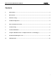
Motor Control I/O Board User’s Manual Contents 1. Introduction.....................................................................................................................................1 2. Kit Contents ....................................................................................................................................1 3. Hardware Setup ..............................................................................................................................2 4.
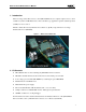
Motor Control I/O Board User’s Manual 1. Introduction The low-voltage starter kit for motor control (MC-LVKIT-714) is a complete 3-phase motor control evaluation system for NEC Electronics’ microcontroller-type, application-specific standard products (ASSPs) for motor control. The kit contains all necessary hardware and software to quickly set up and run a low-voltage brushless DC motor (BLDCM). Figure 1. Motor Control Starter Kit 2.
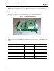
Motor Control I/O Board User’s Manual For the instruction descriptions, refer to the 78K/0 Series Instruction User’s Manual (U12326E) 3. Hardware Setup The kit can be purchased as one unit with all three boards connected as shown below: Figure 2. MC-LV-KIT-714 Boards Stacked Up To attach the motor, connect the phase U, V and W terminals to the J3 connector block on the MCPWR-LV power board and the Hall sensor terminals to the J5 connector block on the MC-IO control board. Table 1.
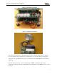
Motor Control I/O Board User’s Manual Figure 3. Motor Phase Connections Figure 4. Hall Sensor Connections The software to run the motor is programmed into the microcontroller’s flash memory. After the motor is connected, the program is ready to run the motor as soon as the 15VDC power supply is plugged into J6 of the MC-IO board and power switch SW1 on the MC-PWR-LV power module is turned ON.
Motor Control I/O Board User’s Manual To control the motor from a GUI on your PC, connect a serial cable to the J9 RS-232 port on the MC-IO board and rebuild the code with the GUI macro option as described later in this manual. Figure 5. Standalone Operation Three seconds after power up, the LED displays the current set speed. Figure 6. Speed Display 4. Standalone Operation After power up in standalone mode, the motor can be operated as follows: 1. Press the START/STOP button to run the motor. 2.
Motor Control I/O Board User’s Manual condition is displayed on the seven-segment LED. For details on the protection functions implemented in hardware, consult the user’s manual for MC-PWR-LV low-voltage power module. The sample code software also has built-in fault detection algorithms as an extra measure of protection. Consult the software manual for details.
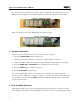
Motor Control I/O Board User’s Manual Figure 7. Motor Control Software and Documents Installation GUI 4. Install all of the software in the following recommended sequence: • NEC Electronics C compiler and assembler software • MC-LVKIT-714 software Figure 8. Software Installation Window 8. Using the NEC Electronics C Compiler and Source Code Debugger To set up the MC-LVKIT-714 starter kit for debugging, follow the steps below. 1.
Motor Control I/O Board User’s Manual 2. Remove jumpers JP5 2-5, JP5 3-6 and 2JP7 1-2 and reconnect M-78F0714 to MC-IO board.
Motor Control I/O Board User’s Manual Figure 9. Jumpers for Standalone Operation Figure 10. Debugging Setup 3. Attach the on-chip debugging emulator’s target connector to 2JP7 on the M-78F0714 and the USB cable to your computer as shown bellow.
Motor Control I/O Board User’s Manual Figure 11. Debugging Environment Shown with QB-78K0MINI On-Chip Debugger Note: The on-chip debugger has a 5 MHz internal clock source by default. The MC-78F0714 must be operated at 20 MHz. Use the external 20 MHz oscillator supplied with the kit. Consult the on-chip debugger user’s manual for information about how to attach the external oscillator.
Motor Control I/O Board User’s Manual Figure 12. PM Plus Workspace 4. Click File and select Open Workspace. 5. Browse to C:\NECTools32\ \Motor_Control\BLDC_Hall_714 and select BLDC_LV.prw PM Plus workspace file. 6. The newly loaded workspace file will contain one project called LV_BLDC_Hall-714.prj as shown below. Figure 13. PM Plus Window 7. To recompile the code, click Build and select Rebuild. 8. At this point, you may change the code and recompile as needed. 9.
Motor Control I/O Board User’s Manual through the on-chip debugging emulator and the source code displayed in the Debugger window as shown below. Figure 14. Source Code in Debugging Window 2. Use the RUN command to execute code in debugging mode. At this point, the motor can be controlled from the user interface in standalone mode or GUI mode. 3. Stop execution using the STOP button. 4. For details on how to use the debugger, consult the ID78K0-QB User’s Manual.
Motor Control I/O Board User’s Manual 10. GUI Operation To operate the motor from the PC GUI, the code has to be rebuilt with “GUI” option. Select Compiler Options from PM+ Tool menu and type “GUI” in Preprocessor Define Macro entry. Figure 15. Compiler Options for PC GUI Operation Rebuild and download the code to the microcontroller flash. At this point the motor can be controlled from the GUI only.
Motor Control I/O Board User’s Manual The GUI will launch if the connection is established: Figure 17. BLDCM GUI 2. To operate the motor, use the controls in the GUI. 3. To change the PID parameters click on the tuning key symbol Figure 18. Launching PID Parameter Window The tuning window will allow the changing of P, I or D constants: Figure 19. PID Parameter Window The new parameter values will be updated in the internal RAM when the motor is restarted again.