
User's Guide


5-16
Upgrades and Options
4. Install a terminator card into the CPU 2 socket.
5. Remove the CPU 2 voltage module.
6. Move the CPU 2 jumper J50 from pins 1-2 to pins 2-3
(Figure 4-1).
7. Replace the side panel and turn on the system.
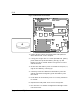
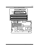
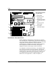
DIMMs
The system board contains four DIMM sockets labeled
J17 through J20 (Figure 5-7). Each socket can hold a
single 72-bit DIMM module with 32MB, 64MB, or
128MB of memory. When all four sockets are populated,
the system board supports a maximum of 512MB of
memory with 128MB DIMMs. A DIMM should be
installed in the bottom (J20) socket. When you install
additional DIMMs, you must start with the first empty
socket above DIMMs already installed. When you
remove DIMMs, you must start with the first DIMM
socket closest to the top edge of the system board.