
User's Guide


5-20
Upgrades and Options
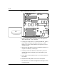
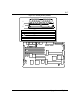
Figure 5-8. PCI and ISA Slot Locations
J3
J4
J5
J9
J6
J10
J11
ISA
ISA
ISA
ISA
PCI
PCI
PCI
A
B
D
C
E
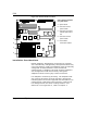
Option board connectors
on system board
A System board
B Connectors for PCI
option boards
C Connectors for shared
PCI/ISA option board
slot
D Connectors for ISA
option boards
E Internal SCSI
termination resistors
Installation Considerations
Newer adapters, designed for Plug-and-Play systems,
are automatically configured by the system without any
user intervention. Older ISA adapters must be manually
configured as detailed below. Once the manual
configuration is complete, the Plug-and-Play adapters
are configured around the manually configured
adapters without causing any resource conflicts.
ISA adapters can be Plug-and-Play. ISA adapters that
are not Plug-and-Play must be manually configured
following the instructions supplied with the board. The
configuration is defined to the system by creating the
ISA configuration file when running the RCU. For
details on running the RCU, refer to Chapter 4.