
User's Guide


5-24
Upgrades and Options
4. Remove the option board from its protective wrapper,
holding the board only by the edges. Do not touch the
board components or the gold connectors.
5. Record the option board serial number in the
equipment log.
6. Set any board jumpers or switches as described in
the documentation that comes with the option board.
Note: Refer to the documentation accompanying the
option board for information on whether the board is
to be installed in a PCI or ISA expansion slot.
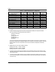
7. Refer to Table 5-1 to determine the recommended
option board slot assignment and configuration
parameters. Refer to Figure 5-8 to determine system
board slot locations.
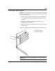
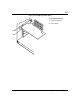
8. Holding the board by its top edge or upper corners,
firmly press the board into an expansion slot on the
system board. The tapered foot of the option board
retaining bracket must fit into the mating slot in the
expansion slot frame (Figure 5-10).
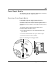
9. Align the rounded notch in the retaining bracket
with the threaded hole in the expansion slot frame.
The retaining bracket fits into the space that was
occupied by the expansion slot cover.
10. Reinstall the screw in the threaded hole. Be sure to
push the bracket slot up against the screw before you
tighten it. If this is not done, the bracket may
interfere with an adjacent bracket.
11. If you have installed a SCSI host adapter board, go
to Appendix A for procedures on cabling these boards
into the system. For all other boards, continue with
step 12.
12. Connect any external cables (if they are needed) to
the installed option board.
13. Replace the side panel, power on the system, and run
the RCU if you have installed any non-plug and play
ISA option boards.