
User's Guide


5-38
Upgrades and Options
11. Remove the device from its protective wrapper and
place it on an antistatic surface. Record the drive
model and serial number in the equipment log.
12. Set any device jumpers or switches on the device. See
the documentation that came with the device.
Notice: When using SCSI optional devices, the SCSI
termination resistors must be installed in the last SCSI
device of the daisy chain cabling. All other devices must
have terminators removed.
Notice: When using an IDE optional device, the device
jumper must be set as the slave device.
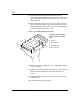
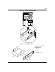
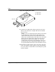
13. Using the four screws supplied with the drive,
reinstall the side rails just removed from the blank
panel tray (Figure 5-18, A). Attach the rails to each
side of the device (C) by using only the bottom screw
holes, as shown. The rails for each side of the device
are identical.
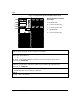
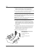
14. Engage the device side rails into the bay guide rails
(see Figure 5-19). Ensure that the device side rails
(see Figure 5-19, A) are inside the bay guide rails
exactly as shown in Figure 5-19, B.
Figure 5-18. Attaching Side Rails to a Device
A
C
B
D
C
Attaching side rails to removable media
drive or diskette drive
A Chassis mounting screws
B Side rails
C Four drive mounting screws
D Drive