
User's Guide


2-24
Features
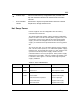
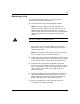
Figure 2-7. Power Supply Module Features
B
E
C
D
F
G
A
H
A Power cage
B Main power switch
C LED: DC ON (Green)
D LED: Alarm (Amber)
E Power supply modules
F Basic power slot (slot 1)
G Redundant power slot (slot R)
H Reserved for future use (slot 2)
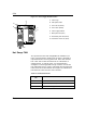
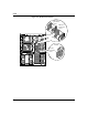
Hot Swap FAN
The system has five hot swappable fan modules (six
fans). The failed fan module can be easily removed or
replaced without turning power off. Each fan module
has a fan alarm LED and each fan is redundant in
configuration. If one fan fails, its associated fan
changes its rotating speed to high. Table 2-4 lists the
fan redundant pairs. Figure 2-8 shows the fan features
from the front of the chassis and Figure 2-9 shows the
fan features from the rear of the chassis.
Table 2-4. Fan Redundant Pairs
Redundant
Pair
Fan Modules
1 CPU Front and CPU Rear
2 Option Board (dual fan)
3 Hard Disk Drive Upper and Hard Disk Drive Lower