
User's Guide


4-25
Configuring Your System
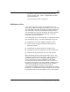
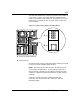
The function select DIP switches configure the modes of
your server. Figure 4-1 shows the DIP switches that
consist of a block of four switches, accessible on the I/O
panel that is located on the I/O riser board at the rear
of the chassis.
Figure 4-1. Function Select Switches and Dump Button
A
B
1
2
3
4
ON
A Function select switches
B Dump button
Situations that require changing switch settings include
using an uninterruptible power supply.
Note: The switches are set correctly at the factory for
your system configuration. If your system requires a
switch change, change only the switch setting for that
condition. Otherwise keep the switches at their factory
settings.
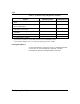
Table 4-9 shows the switch configurations and
functions. Set the switches per Table 4-9 and the
following steps.