User’s Guide NEC Express Server Express5800 Series Express5800/R120f-1M EXP801 Chapter 1 General Description Chapter 2 Preparations Chapter 3 Setup Chapter 4 Appendix 10.107.01-101.
Documents Provided with This Product Documents Provided with This Product Documents for this product are provided as accompanying booklets ( within EXPRESSBUILDER DVD ( ). ) and as electronic manuals ( PDF ) stored Safety Precautions and Regulatory Notices Describes points of caution to ensure the safe use of this server. Read these cautions before using this server. Getting Started Describes how to use this server, from unpacking to operations.
Contents Contents Documents Provided with This Product ................................................................................................................. 2 Contents ................................................................................................................................................................ 3 Notations Used in This Document .........................................................................................................................
Contents Chapter 2 4 Preparations ..................................................................................................................................... 38 1. Installing Internal Optional Devices ............................................................................................................. 39 1.1 Safety Precautions........................................................................................................................... 39 1.2 Anti-static Measures .........
Contents Chapter 3 Setup .............................................................................................................................................. 109 1. Turning on the Server ............................................................................................................................... 110 1.1 POST ............................................................................................................................................. 111 1.1.1 POST sequence ....
Notations Used in This Document Notations Used in This Document Notations used in the text In addition to safety-related symbols urging caution, 3 other types of notations are used in this document. These notations have the following meanings. Important Indicates critical items that must be followed when handling the server or operating software. If the procedures described are not followed, server failure, data loss, and other serious malfunctions could occur.
Notations Used in This Document Abbreviations of Operating Systems (Windows) Windows Operating Systems are referred to as follows. Refer to Chapter 1 (1.2 Supported Windows OS) in Installation Guide (Windows) for detailed information.
Trademarks Trademarks EXPRESSSCOPE and ExpressUpdate are registered trademark of NEC Corporation. Microsoft, Windows, Windows Server, Windows Vista, and MS-DOS are registered trademarks or trademarks of Microsoft Corporation in the United States and other countries. Intel, Pentium, and Xeon are registered trademarks of Intel Corporation of the United States. AT is a registered trademark of International Business Machines Corporation of the United States and other countries.
License Agreement Notice License Agreement Notice Open source software of following license is included in the part of this product (system BIOS). • EDK from Tianocore.org • UEFI Network Stack 2 • Crypto package using WPA Supplicant Open source software of following license is included in the part of this product (Off-line Tools). • EDK from Tianocore.org EDK FROM TIANOCORE.ORG BSD License from Intel Copyright (c) 2012, Intel Corporation All rights reserved.
License Agreement Notice UEFI NETWORK STACK 2 OpenSSL License ------Copyright (c) 1998-2011 The OpenSSL Project. All rights reserved. Redistribution and use in source and binary forms, with or without modification, are permitted provided that the following conditions are met: 1. 2. 3. 4. 5. 6. Redistributions of source code must retain the above copyright notice, this list of conditions and the following disclaimer.
License Agreement Notice CRYPTO PACKAGE USING WPA SUPPLICANT WPA Supplicant ------Copyright (c) 2003-2012, Jouni Malinen and contributors All Rights Reserved. This program is licensed under the BSD license (the one with advertisement clause removed). If you are submitting changes to the project, please see CONTRIBUTIONS file for more instructions.
Warnings and Additions to This Document Warnings and Additions to This Document 1. Unauthorized reproduction of the contents of this document, in part or in its entirety, is prohibited. 2. The contents of this document may change without prior notice. 3. Do not make copies or alter the document content without permission from NEC Corporation. 4. Every effort has been made to ensure the completeness of this document.
Warnings and Additions to This Document Safety precautions Follow the instructions in this document for the safe use of NEC Express server. This User’s Guide describes hazardous parts of the server, possible hazards, and how to avoid them. Server components with possible danger are indicated with a warning label placed on or around them (or, in some cases, by printing the warnings on the server). In User’s Guide or on warning labels, WARNING or CAUTION is used to indicate a degree of danger.
Warnings and Additions to This Document Safety notes To use this server safely, read thoroughly the "Safety Precautions and Regulatory Notices" that comes with your server. For symbols used in this document, refer to "Safety Indications" in "Safety Precautions and Regulatory Notices". Warning label are attached on or near the components with potential hazards. (This label is either attached or printed on the component.) Do not remove or black out this label and keep it clean.
Warnings and Additions to This Document Handling precautions (for proper operations) Be sure to observe the following precautions for the proper functioning of the server. Ignoring the precautions may cause server malfunction or failure. • Do not use any cell phone or PHS and switch off them near the server. Electric waves from such devices can cause server to malfunction. • Install the server in an appropriate place. For details about the installation location, refer to Chapter 2 Preparations (2.
Warnings and Additions to This Document Handling precautions (for anti-static measures) The server contains electronic components sensitive to static electricity. Avoid failures caused by static electricity when installing or removing any optional devices. • Wearing Anti-static Wrist Strap Or Anti-static Gloves Wear a wrist strap on your wrist and connect the wire to the chassis.
Warnings and Additions to This Document Tips for your health and safety Using a computer extensively may affect different parts of your body. Here are tips you should follow while working on a computer to minimize strain on your body. Keep proper posture The basic body position for using a computer is sitting straight with your hands on the keyboard parallel with the floor, and your eyes directed slightly downward toward the monitor.
1 NEC Express5800 Series Express5800/R120f-1M General Description This chapter introduces the features of this server and the name of each part. 1. Introduction 2. Accessories Verify the condition of your server's accessories. 3. Standard Features This section describes the server’s features and the server management. 4. Names and Functions of Parts This section describes the name of each part contained in this server.
Chapter 1 1. General Description 1. Introduction Introduction Thank you for purchasing this NEC Express5800 Series product. ® ® This high performance server is powered by the latest microprocessor "Intel Xeon processor. NEC’s latest technology and architectures realize high-power and high-speed operation that cannot be matched by existing servers. The server is designed with consideration of not only reliability but also expandability, which enables you to use it as a network server.
Chapter 1 General Description 2. 2. Accessories Accessories The carton box contains various accessories which are required for setup or maintenance. Make sure you have them all for future use. • Front Bezel • Bezel Lock Key (attached to Front Bezel) • Slide Rails • EXPRESSBUILDER • Safety Precautions and Regulatory Notices • SAS/SATA cable (RAID controller is unmounted) • Getting Started *1 *1 Instruction manuals are stored in EXPRESSBUILDER.
Chapter 1 General Description 3. 3. Features Features The server has the following features: High performance • ® ® Intel Xeon processor – N8101-768F : E5-2603 v3 (1.60GHz 6Core) – N8101-769F : E5-2609 v3 (1.90GHz 6Core) – N8101-770F : E5-2620 v3 (2.40GHz 6Core) – N8101-773F : E5-2640 v3 (2.60GHz 8Core) – N8101-775F : E5-2650L v3 (1.80GHz 12Core) – N8101-776F : E5-2660 v3 (2.60GHz 10Core) – N8101-778F : E5-2670 v3 (2.30GHz 12Core) – N8101-779F : E5-2690 v3 (2.
Chapter 1 General Description 3.
Chapter 1 General Description 3. Features Self-diagnosis • Power On Self-Test (POST) • Test and Diagnosis (T&D) utility Easy setup • EXPRESSBUILDER (setup utility) • BIOS Setup utility (SETUP) Maintenance features • Off-line Tools • Memory dump feature using DUMP Switch • Feature to back up and restore BIOS/BMC settings using EXPRESSSCOPE Profile Key ® *1: Unsupported on Xeon processor E5-2603 v3, E5-2609 v3 embedded models.
Chapter 1 3.1 General Description 3. Features Firmware and Software Version Management Use of NEC ESMPRO Manager and ExpressUpdate Agent allows you to manage versions of firmware and software as well as update them by applying update packages. This feature automatically updates modules without stopping the system just by specifying the updating packages from NEC ESMPRO Manager.
Chapter 1 General Description 4. 4. Names and Functions of Parts Names and Functions of Parts This section describes the names of the server parts. 4.1 Front View (With Front Bezel) (7) (6) (5) (1) (4) (3) (2) (1) Front Bezel (4) POWER CAPPING LED The cover to protect the front of the server. This cover can be locked with the provided Bezel Lock Key. This LED indicates enabled/disabled status of power capping feature. (See page 34.
Chapter 1 General Description 4.2 4. Names and Functions of Parts Front View (Without Front Bezel) (16)-1(16)-2 (14) (17) (12) (15) (18) (13) (11) (8)-2 (8)-0 (8)-1 (9) (10) (9) (8)-4 (8)-3 (10) (9) (8)-5 (10) (9) (10) (9) (10) (8)-7 (21) See (3) to (5) on previous page. (20) (22) (8) 2.5-inch had disk drive bay (15) BMC RESET Switch The bay where hard disk drives are installed. The sequential numbers indicate the corresponding slot numbers. All bays include Dummy Trays.
Chapter 1 4.3 General Description 4. Names and Functions of Parts Rear View (1) (4) (2) (5) (13) (14) (12) (6) (18) (7) (15) (3) (8) (11) (9) (9) (12) (11) (10)-1 (1) Power unit (Power supply slot 1) The power unit supplies DC power to the server. (2) AC Inlet This socket is used to connect the power cord. The LED indicates the transfer speed of LAN ports. (See page 36.) (12) Management LAN connector A LAN connector which supports 1000BASE-T/100BASE-TX/10BASE-T.
Chapter 1 4.4 General Description 4. Names and Functions of Parts External View (2) (1) (4) (3) (4) (1) Top Cover (2) Release Button.
Chapter 1 4.5 General Description 4. Names and Functions of Parts Internal View (5) (4) (2) (6) (11)-2 (3)-1 (7) (8) (3)-2 (3)-3 (9) (3)-4 (3)-5 (3)-6 (3)-7 (3)-8 (10) (1) (1) (11)-1 (12) Front Panel Board (5) DIMM (optional) (2) Backplane (6) Support bar (3) Cooling Fan (7) Motherboard -1 FAN1F/R -2 FAN2F/R -3 FAN3F/R -4 FAN4F/R -5 FAN5F/R -6 FAN6F/R (optional) -7 FAN7F/R (optional) -8 FAN8F/R (optional) FAN1 to FAN5 are factory installed.
Chapter 1 4.6 General Description 4.
Chapter 1 (1) General Description 4. Names and Functions of Parts (17) SPI Mezzanine connector Processor (CPU) socket EXPRESSSCOPE Profile Key (SPI memory) has been installed, where BIOS and BMC configuration data is stored. Relocate it when replacing motherboard to inherit configuration data.
Chapter 1 General Description 4. Names and Functions of Parts 4.7 Status Indicators 4.7.1 POWER LED ( ) POWER LED indicates power ON/OFF status of the server. POWER LED pattern 4.7.2 Description On (green) The server is normally powered on. Off The server is off-powered. The server is in halt status. STATUS LED 1,2 ( ) While hardware is operating normally, STATUS LED 1 lights green. STATUS LED 2 is off. STATUS LED 1 is off or STATUS LED 2 lights/flashes amber if there is a hardware failure.
Chapter 1 General Description STATUS LED 1,2 pattern STATUS LED 1 STATUS LED 2 Off On (amber) 4. Names and Functions of Parts Description Solution A temperature alarm was detected. Check the internal fan for dusts. Also check if the fan unit is properly connected. If the LED indication does not change, contact your sales representative. A CPU error occurred. Turn the power off and then turn it on. If POST displays any error message, take notes of the message, and contact your sales representative.
Chapter 1 4.7.3 General Description LINK/ACT LED ( 4. Names and Functions of Parts 1, 2, 3, 4) LINK/ACT LED on front panel indicates the status of LAN port. The number of ports depends on an optional LOM card installed. LINK/ACT LED pattern 4.7.4 Description On (green) The server is connected with network normally. Flashing (green) The server is accessing network. Off The server is disconnected from network.
Chapter 1 General Description 4. Names and Functions of Parts LED on a hard disk drive 4.7.7 Each HDD is equipped with DISK LED. DISK LED 1 (green) DISK LED 1, 2 pattern DISK LED 1 DISK LED 2 (amber) Description DISK LED 2 Solution Flashing (green) Off Hard disk drive is being accessed. Off On (amber) (only when RAID system is configured) Hard disk drive is failing. Flashing (green) Flashing (amber ) (only when RAID system is configured) Rebuild is in progress.
Chapter 1 4.7.8 General Description 4. Names and Functions of Parts LEDs for LAN connectors The LAN connectors have LINK/ACT LED and SPEED LED. The figure below shows when an optional LOM card N8104-154 is installed. SPEED LED LINK/ACT LED SPEED LED Data LAN connector Management LAN connector LINK/ACT LED • LINK/ACT LED ( 1, 2, 3, 4, M) This LED indicates the state of the LAN port. LINK/ACT LED pattern • Description On (green) The server is connected with network normally.
Chapter 1 General Description 4. Names and Functions of Parts AC POWER LED on Power Unit 4.7.9 The power unit is equipped with AC POWER LED. AC POWER LED AC POWER LED pattern Description Solution On (green) The server is powered on. – Flashing (green) The power cable is connected and AC power is supplied. – Cold Redundant feature is enabled. (See page 95.) – On (amber) The power cable is not connected in redundant power configuration. Connect the power cable. Power unit is failing.
2 NEC Express5800 Series Express5800/R120f-1M Preparations This chapter describes preparations for using this server. 1. Installing Internal Optional Devices You can skip this section if you did not purchase any optional devices. 2. Installation and Connection Place the server in a suitable location and connect cables following this section.
Chapter 2 Preparations 1. 1. Installing Internal Optional Devices Installing Internal Optional Devices This section describes the instructions for installing supported optional devices and precautions. If you did not purchase any optional device requiring installation, you may skip this section. • We recommend that optional devices be installed by a maintenance Important service staff from your maintenance service company authorized by NEC. • Use only the devices and cables specified by NEC.
Chapter 2 Preparations 1.2 1. Installing Internal Optional Devices Anti-static Measures The server contains electronic components sensitive to static electricity. Avoid failures caused by static electricity when installing or removing any optional devices. • Wearing Anti-static Wrist Strap Or Anti-static Gloves Wear a wrist strap on your wrist and connect the wire to the chassis.
Chapter 2 Preparations 1.3 1. Installing Internal Optional Devices Overview of Installation and Removal Install/remove components by using the following procedure. Installing/removing internal components except for hard disk drives, fan unit, and power supply unit should be done after dismounting the server from the rack. It is recommended that more than one person removes the server from the rack. CAUTION Be sure to observe the following precautions to use the server safely.
Chapter 2 Preparations 1. Installing Internal Optional Devices 9. Mount the server onto the rack. See Chapter 2 (2.1.2 (1) Installation). 10. Install hard disk drives See Chapter 2 (1.18 Hard Disk Drive). 11. Install power supply units See Chapter 2 (1.19 Power Supply Unit). 12. Attach Front Bezel. See Chapter 2 (1.20 Installing Front Bezel). This is the end of the installation or removal procedures for internal optional devices. Continue the setup with reference to Chapter 2 (2.2 Connection).
Chapter 2 Preparations 1.4 1. Installing Internal Optional Devices Confirming Servers (UID Switch) Using UID (Unit ID) Switch helps you to identify the target server. When the server is working, before you turn the server off or disconnect a cable from the server, be sure to identify the target server by using UID Switch first. To turn UID LED on, press UID Switch. When it is pressed again, the LED will be off.
Chapter 2 Preparations 1.5 1. Installing Internal Optional Devices Removing Front Bezel You need to remove the front bezel when pressing the POWER switch or removing the top cover. 1. Insert the attached Bezel Lock Key into the key slot and turn the key to the front bezel side while pressing it lightly to release the lock. Unlocked Locked 2. Hold the right end of front bezel and pull it toward you, and remove the right end from the chassis. 3.
Chapter 2 Preparations 1.6 1. Installing Internal Optional Devices Removing Top Cover You need to remove top cover when installing or removing the optional component or change internal cable connection. 1. See steps 1 to 5 in Chapter 2 (1.3 Overview of Installation and Removal) for preparations. 2. Loosen thumb nut located on rear panel. 3. Slide Top Cover toward the rear of the server while pressing Release Button on the cover. 4. Lift the cover, and remove it from the server.
Chapter 2 Preparations 1.7 1. Installing Internal Optional Devices TPM Kit This section describes the procedure for installing optional TPM Kit. Connector for TPM Kit 1.7.1 Installation Install TPM Kit in the following procedure. 1. See steps 1 to 6 in Chapter 2 (1.3 Overview of Installation and Removal) for preparations. 2. Install TPM Kit and secure it by pushing the nylon rivet attached to TPM Kit. Important The TPM kit once installed cannot be removed.
Chapter 2 Preparations 1.8 1. Installing Internal Optional Devices Processor (CPU) You can configure the multi-processor system by adding an optional processor (called CPU hereafter). Important • You must avoid static electricity to work with the procedure below. For details, see Chapter 2 (1.2 Anti-static Measures). • Make sure to use the CPU authorized by NEC. Installing a third-party CPU may cause a failure of the CPU as well as the motherboard.
Chapter 2 Preparations 1.8.2 1. Installing Internal Optional Devices Installation Follow steps below to install the CPU. 1. See steps 1 to 6 in Chapter 2 (1.3 Overview of Installation and Removal) for preparations. 2. Locate the CPU socket to which you are going to install a CPU. 3. Remove the screws that secure the dummy cover, and remove it. Note Keep the removed dummy cover for future use. 4. Remove the protective cover from the CPU socket.
Chapter 2 Preparations 1. Installing Internal Optional Devices 5. Push down the socket lever marked with " the lever until it stops. →" once to unlatch it from the hook, then slowly open 6. Push down the socket lever marked with "← the lever until it stops. " once to unlatch it from the hook, then slowly open 7. Lift the plate. Important Do not touch the socket contacts.
Chapter 2 Preparations 1. Installing Internal Optional Devices 8. Put the additional CPU on the CPU socket slowly and gently. For easy installation, hold edges of CPU with your thumb and index fingers so that the notch is aligned with the key on the CPU socket. Important • Be sure to hold the CPU only at the edges. • Pay attention not to touch the bottom of the CPU (pin section). Note • Insert the CPU while aligning the notch on the CPU with the key on the CPU socket.
Chapter 2 Preparations 1. Installing Internal Optional Devices 11. Close the socket lever marked with " →" to fix it. 12. Put the heat sink on the CPU and fix the heat sink with four screws. Temporarily tighten the four screws diagonally, then tighten them securely. Make sure that the screw aligns with the screw hole. If not, the screw may damage the motherboard. 13. Make sure that the heat sink is installed on a level with the motherboard.
Chapter 2 Preparations 1. Installing Internal Optional Devices 14. Install an additional fan unit provided with additional CPU board. Remove fan cover from the slot where you are going to install an additional fan unit. 15. Install the three additional fan units 16. Continue to install or remove internal optional devices, mount and connect the server, and turn it on. 17. Run BIOS Setup Utility (SETUP) to confirm the following settings. See Chapter 2 (1. System BIOS) in "Maintenance Guide".
Chapter 2 Preparations 1.8.3 1. Installing Internal Optional Devices Replacement / Removal Important • Do not remove any CPU unless it is failed. • To remove the heat sink from the CPU, first turn the heat sink to the left and right lightly to make sure that the heat sink can be apart from the CPU. Removing the heat sink with it adhering to the CPU may cause the CPU and/or CPU socket to be defected.
Chapter 2 Preparations 1.9 1. Installing Internal Optional Devices DIMM Install a DIMM (Dual Inline Memory Module) to a DIMM socket on the motherboard in the server. The motherboard provides twenty-four sokets to install DIMMs. Important • You must avoid static electricity to work with the procedure below. For details, see Chapter 2 (1.2 Anti-static Measures). • Use only the specified DIMMs. Installing a DIMM from a third party may damage not only the DIMM but the motherboard.
Chapter 2 Preparations 1.9.2 1. Installing Internal Optional Devices Memory Clock The server supports the memory clock speed of DDRL4-1600/1866/2133MHz. However, the actual memory clock speed depends on CPU and memory configuration. (The all of DIMMs operate at the same clock speed.
Chapter 2 Preparations N code (CPU) N8101-775F (E5-2650Lv3) N8101-776F (E5-2660v3) N8101-778F (E5-2670v3) N8101-779F (E5-2690v3) N8101-930F (E5-2695v3) N8101-931F (E5-2697v3) N8101-932F (E5-2698v3) N8101-933F (E5-2699v3) 56 1.
Chapter 2 Preparations 1.9.3 1. Installing Internal Optional Devices Memory RAS Feature The server supports the following RAS features. Some restrictions (e.g., DIMM installation location) are imposed on using the Memory Mirroring or Memory LockStep feature. See Chapter 2 (1.10.7 Using Memory RAS Feature) for conditions appropriate to your requirements.
Chapter 2 Preparations 1.9.4 1. Installing Internal Optional Devices DIMM installation order Note DIMM installation order in 1-CPU configuration differs from that in 2-CPU configuration. In 1-CPU configuration, install two DIMMs starting from the smallest slot number. If CPU2 is not installed, CPU2_DIMM1 to CPU2_DIMM12 are disabled. In 2-CPU configuration, alternately install two DIMMs starting from the smallest slot number of each CPU. See the table below to find allowable combination of DIMMs.
Chapter 2 Preparations 1.9.5 1. Installing Internal Optional Devices Installation Install a DIMM by using the following procedure. 1. See steps 1 to 6 in Chapter 2 (1.3 Overview of Installation and Removal) for preparations. 2. Open levers on left and right sides of DIMM slot, and remove the dummy cover. Note Keep the removed dummy cover for future use. 3. Push the DIMM straight into the socket. When a DIMM is inserted into the socket, the lever automatically closes.
Chapter 2 Preparations 1.9.6 1. Installing Internal Optional Devices Removal / Replacement To remove DIMM, reverse the installation procedure. Be sure to install dummy cover to the slots from where DIMMs are removed. Important Failing to install dummy cover to vacant slot may cause malfunction of the server due to insufficient cooling effect. Note When removing a defective DIMM, check error messages displayed at POST or NEC ESMPRO and check the DIMM socket where the defective DIMM is installed.
Chapter 2 Preparations 1. Installing Internal Optional Devices (1) Memory Mirroring Feature Memory Mirroring feature writes the same data into two groups of DIMMs (mirror set) corresponding with each other between memory channels (channels 0 and 1 or channel 2 and 3) to provide data redundancy. Note • Memory Mirroring feature uses channels 0 and 1 or channels 2 and 3. • To use Memory Mirroring feature, install N8102-618/619 additional memory board (two DIMMs of same model).
Chapter 2 Preparations 1. Installing Internal Optional Devices Memory Mirroring feature can be used under the following conditions: • Install DIMMs in DIMM sockets to configure a mirror set. • All the installed DIMMs should have the same capacity. • See Chapter 2 (1. System BIOS) in "Maintenance Guide", check if your server supports Memory Mirroring feature. Select Advanced → Memory Configuration → Memory Information, and check if Supported is displayed in Mirroring. • See Chapter 2 (1.
Chapter 2 Preparations 1. Installing Internal Optional Devices (2) Memory Lock Step Feature (x8 SDDC) In Memory Lock Step feature, the DIMMs in two groups corresponding to two memory channels (channels 0 and 1, or channels 2 and 3) is multiplexed and operated in parallel to enable x8 SDDC (x8 Single Device Data Correction). With this feature, a single device can detect and correct one to eight-bit error. Note • Memory LockStep feature uses channels 0 and 1 or channels 2 and 3.
Chapter 2 Preparations 1. Installing Internal Optional Devices Memory Lock Step feature can be used under the following conditions: • Install DIMMs in DIMM socket to configure a Lock Step set. • All the installed DIMMs should have the same capacity. • See Chapter 2 (1. System BIOS) in "Maintenance Guide", run SETUP, change parameters as shown below, save the settings, and exit from SETUP. Advanced → Memory Configuration → Memory RAS Mode → Change to LockStep.
Chapter 2 Preparations 1. Installing Internal Optional Devices (3) Memory Sparing Feature Memory Sparing feature puts a memory channel 2 of a memory controller in each CPU into standby status as spare devices. If a correctable error occurs in a DIMM in the running memory controller, the feature automatically changes the running DIMM from the failed one to a DIMM in the standby state to continue the processing.
Chapter 2 Preparations 1. Installing Internal Optional Devices Memory controller Standby Running Spare set #1 Spare set #3 Spare set #5 Spare set #7 Memory controller Standby Running Spare set #2 Spare set #4 Spare set #6 Spare set #8 Memory Sparing feature can be used under the following conditions: 66 • Install DIMMs in DIMM socket to configure a spare set. • DIMMs to be installed should have the same capacity. • See Chapter 2 (1.
Chapter 2 Preparations • 1. Installing Internal Optional Devices Installation order depends on CPU configuration. See the figure below.
Chapter 2 Preparations 1. Installing Internal Optional Devices 1.10 Flash Backup Unit for RAID Controller If a RAID Controller (N8103-176/177/178/179) is installed, use the flash backup unit (FBU) to avoid data loss caused by accidents including temporary blackout during a Write Back operation. The model of the flash backup unit to be used depends on RAID Controller. • • 1.10.1 For N8103-176/177/178, use N8103-181 Flash Backup Unit For N8103-179, use FBU provided with N8103-179.
Chapter 2 Preparations 1. Installing Internal Optional Devices 3. Put the FBU on battery tray for RAID Controller. Secure the FBU bracket that comes with FBU with the screw. 4. Connect the FBU control cable (650 mm) that comes with FBU. 5. Remove the two screws from RAID Controller, and remove PCI bracket. 6. Mount the adapter to RAID Controller.
Chapter 2 Preparations 1. Installing Internal Optional Devices 7. Connect the control cable of FBU to RAID Controller. Align the connector on FBU control cable with the black marking on RAID Controller, then connect the FBU control cable. 8. Remove the two screws from server chassis, and remove the RAID Controller bracket. 9. Install the RAID Controller bracket to RAID Controller using two screws you have removed in Step 6. 10.
Chapter 2 Preparations 1. Installing Internal Optional Devices 12. Disconnect USB cable (for front) from motherboard. 13. Connect Mini SAS HD cable to RAID Controller. 14. Connect USB cable (for front) to motherboard. 15. Install support bar and PCI riser card you have removed in Steps 2 and 3. 1.10.3 Removal For removing the FBU for RAID Controller, reverse the installation procedure.
Chapter 2 Preparations 1.10.4 1. Installing Internal Optional Devices Installing FBU for N8103-179 Take the steps below to install FBU. 1. See steps 1 to 6 in Chapter 2 (1.3 Overview of Installation and Removal) for preparations. 2. Remove the two screws, then remove the PCI riser card. 3. Put the FBU, provided as the standard accessory of RAID Controller, on the battery tray for RAID Controller.
Chapter 2 Preparations 1. Installing Internal Optional Devices 6. Remove one screw from the blank cover on the PCI riser card (removed in Step 2) on which you are going to mount the RAID Controller, then remove the blank cover. 7. Mount the RAID Controller to PCI riser card, and secure it with one screw you have removed in Step 6. 8. Mount the support bar you have removed in Steps 2 and 3. Note 1.10.5 Keep the removed blank cover for future use.
Chapter 2 Preparations 1. Installing Internal Optional Devices 1.11 LOM Card The server supports LOM Card which is the replaceable onboard network adapter. Install LOM card to the LOM Card slot on motherboard. The motherboard has one slot to install LOM Card. Important You must avoid static electricity to work with the procedure below. For details, see Chapter 2 (1.2 Anti-static Measures). 1.11.1 Installation Follow steps below to install LOM Card. 1. See steps 1 to 6 in Chapter 2 (1.
Chapter 2 Preparations 1. Installing Internal Optional Devices 5. Remove two screws from the motherboard. Screws 6. Align the pin terminals of LOM Card with the LOM Card slot, insert the card , and.secure the card with three screws. 7. Secure the bracket of LOM Card with two screws you have removed in step 3. 8. Install the port cover provided with LOM Card.
Chapter 2 Preparations 1.11.2 1. Installing Internal Optional Devices Removal Remove LOM Card in reverse order of installation steps. Important To maintain the cooling effect in the server, install the blank cover in the vacant LOM Card slot.
Chapter 2 Preparations 1. Installing Internal Optional Devices 1.12 PCI Card This server provides PCI slots for riser card (one Full Height PCI card and one Low Profile PCI card), a slot dedicated for LOM card, and a slot dedicated for RAID controller (total four PCI cards can be mounted). Important You must avoid static electricity to work with the procedure below. For details, see Chapter 2 (1.2 Anti-static Measures). 1.12.1 Notes Read the following notes when installing or removing a PCI card.
Chapter 2 Preparations • 1.12.2 1. Installing Internal Optional Devices For a RAID Controller, LAN card (network boot), or Fibre Channel controller, if a hard disk drive on which an OS is installed is connected, set the option ROM for that slot to Enabled. See Chapter 2 (1. System BIOS) in "Maintenance Guide" for how to specify it. Supported PCI cards and available slots The following tables list supported cards and slots available for them.
Chapter 2 Preparations 1. Installing Internal Optional Devices Slot number PCI standard PCI slot performance *1 Model Product name #1A Standard riser card #1B #1C PCIe 3.0 x8 lane PCI card type *2 Transfer bandwidth (per lane) *1 Slot size Available card size #1D Remarks x8 socket 8Gb/s Dedicated to RAID Controller – Dedicated to LOM card Full height – For additional LAN port. Card type: PCI Express 2.0 (x8) For additional LAN port. Card type: PCI Express 2.0 (x4) For additional LAN port.
Chapter 2 Preparations (2) 1. Installing Internal Optional Devices N8116-33 riser card (PCIex16) (option) Slot number PCI standard PCI slot performance *1 Model Produc t name PCI card type *2 Transfer bandwidth (per lane) *1 Slot size Available card size Riser card (PCIex16) #1B #1C PCIe 3.0 #1A #1D x8 lane X16 lane x8 socket X16 socket Remarks 8Gb/s Dedicated to RAID Controller Dedicated to LOM card Full height – – – Low profile 220 mm max.
Chapter 2 Preparations 1. Installing Internal Optional Devices Slot number PCI standard PCI slot performance *1 Model Produc t name PCI card type *2 Transfer bandwidth (per lane) *1 Slot size Available card size Riser card (PCIex16) #1B #1C PCIe 3.0 #1A #1D x8 lane X16 lane x8 socket X16 socket Remarks 8Gb/s Dedicated to RAID Controller – Dedicated to LOM card Full height – Low profile 220 mm max. N8104-148 10GBASE Adapter (SFP+/2ch) [PCI Express 2.
Chapter 2 Preparations 1.12.3 1. Installing Internal Optional Devices Installation Install a PCI card to the riser card in the following procedure. Important When installing a PCI card, make sure the connector of the card fits the connector of the riser card. • Check the card type (Low Profile or Full Height) which respective riser card Note supports and the type of PCI card to be installed. • When installing an FBU, see Chapter 2 (1.11 Flash Backup Unit for RAID Controller). 1.
Chapter 2 Preparations 1. Installing Internal Optional Devices 6. Secure the PCI card with the screw you removed in step 4. PCIe #1D Low Profile side Tips PCIe #1C Full Height side To connect a PCI card to the connector on motherboard with cable, connect a cable to PCI card before installing PCI riser card. 7. Connect the PCI riser card to the slot on motherboard and secure the card with two screws you removed in step 2.
Chapter 2 Preparations 1.12.5 1. Installing Internal Optional Devices Installing RAID Controller This section describes how to install an optional RAID Controller to the slot dedicated to RAID Controller. (1) When using the optional RAID controller (N8103-176/177/178) For details, see the manual that comes with optional RAID Controller (N8103-176/177/178). Important • You must avoid static electricity to work with the procedure below. For details, see Chapter 2 (1.2 Anti-static Measures).
Chapter 2 Preparations 1. Installing Internal Optional Devices 6. Attach the RAID Controller bracket to RAID Controller with two screws you have removed in Step 4. Ports 4-7 Ports 0-3 7. Insert the RAID Controller slightly into the dedicated slot while tilting the card. 8. Gently place the RAID Controller on bottom plate of chassis so that it become horizontal to the motherboard. 9. Insert the RAID Controller into the slot while keeping horizontal state. 10.
Chapter 2 Preparations 1. Installing Internal Optional Devices 1.13 Optical Disk Drive This section describes the procedure for installing the optional optical disk drive. Important Do not install any unsupported optical disk drive. Optical disk drive bay 1.13.1 Installation Install an optical disk drive in the following procedure. 1. See steps 1 to 6 in Chapter 2 (1.3 Overview of Installation and Removal) for preparations. 2. Remove a screw from the bracket, and remove the bracket. 3.
Chapter 2 Preparations 1. Installing Internal Optional Devices 5. Install the optical disk drive to the tray. 6. Secure the bracket to optical disk drive with a screw you have removed in Step 2. Screw 7. Connect a cable to the optical disk drive. 1.13.2 Removal To remove an optical disk drive, reverse the installation procedure above.
Chapter 2 Preparations 1. Installing Internal Optional Devices 1.14 Use of Internal Hard Disk Drives in the RAID System This section describes how to use the internal hard disk drives in the RAID System. Important If you use hard disk drives in the RAID System or change the RAID level, hard disk drives are initialized. If the hard disk drive contains valuable data, be sure to backup the hard disk drive before installing the RAID Controller and configuring the RAID System.
Chapter 2 Preparations 1.14.2 1. Installing Internal Optional Devices Notes on Building RAID System Note the following points when building a RAID System. • • The number of hard disk drives required varies in each RAID level. If the optional RAID Controller N8103-176 is used, the RAID System cannot be built in RAID5/RAID6/RAID50/RAID60.
Chapter 2 Preparations 1. Installing Internal Optional Devices 1.15 Installing Top Cover When all internal optional devices are installed, close the server with Top Cover. 1. Put Top Cover straight on the server chassis so that it can be surely engaged with the chassis frame. 2. Slide Top Cover toward the front of the server. 3. Tighten the thumb nut on rear of the server.
Chapter 2 Preparations 1. Installing Internal Optional Devices 1.16 Hard Disk Drive Bays for hard disk drives are provided at the front of the server. A hard disk drive mounted in a dedicated drive tray can be purchased. Install the hard disk drive on the server with it mounted in the drive tray. Important Use hard disk drives specified by NEC. Installing a third-party hard disk drive might cause a failure of the server as well as the hard disk drive.
Chapter 2 Preparations 1.16.1 1. Installing Internal Optional Devices Installation Install a hard disk drive by using the following procedure. Note In the RAID System, use hard disk drives that have the same specifications (capacity, rotational speed, and standard) for each Disk Array. 1. See Chapter 2 (1.3 Overview of Installation and Removal) for preparations. 2. Locate the slot where you install the hard disk drive. The server has 8 slots.
Chapter 2 Preparations 1. Installing Internal Optional Devices 6. Slowly close the handle. The tray is locked making a clicking sound. Note When you push the drive into the slot, confirm the handle got hooked on the frame. 7. Run BIOS Setup Utility, and then specify the boot order from Boot menu. For details, see Chapter 2 (1. System BIOS) in "Maintenance Guide" Tips 1.16.2 The saved boot order is cleared when a hard disk drive is added.
Chapter 2 Preparations 1.16.3 1. Installing Internal Optional Devices Replacing a hard disk drive in the RAID System (Auto Rebuild) In the RAID System, you can use the auto rebuild feature to restore data back to the state before a failure occurred. The auto rebuild feature is enabled in logical drives set to RAID 1, RAID 5, RAID 6, RAID 10, RAID 50, and RAID60. The disk array is automatically rebuilt when hot swapping (replacing a hard disk drive while the power on) a failed hard disk drive.
Chapter 2 Preparations 1. Installing Internal Optional Devices 1.17 Power Supply Unit This server can contain two power supply units. The server provides a redundant power configuration that ensures continued operation of the system in the unlikely event one of the power supply units fails. Tips 1.17.1 AC power supply unit has a cable tie to prevent AC cable from slipping out.
Chapter 2 Preparations 1.17.2 1. Installing Internal Optional Devices Installation Follow steps below to install a power supply unit: 1. See steps 1 to 4 in Chapter 2 (1.3 Overview of Installation and Removal) for preparations. 2. Remove the blank cover. Slot for standard power supply unit REAR Note Slot for additional power supply unit Keep the removed blank cover for future use. 3. Insert the power supply unit until it is locked with clicking sound. 4. Connect power cords.
Chapter 2 Preparations 1. Installing Internal Optional Devices AC POWER LED blinks green when the power cord is connected to either of power supply units and the other power supply unit’s AC POWER LED goes on amber. When the power cord is connected to it, AC POWER LEDs on both power supply units blink green. AC POWER LED Power supply unit #1 Power supply unit #2 5. Power on the server. AC POWER LEDs go on green. 6.
Chapter 2 Preparations 1. Installing Internal Optional Devices 1.18 Installing Front Bezel When installing Front Bezel, engage the left end of front bezel with chassis. Then, engage the right end of front bezel with chassis. After installing Front Bezel, lock it with Bezel Lock Key. If you fail to mount the front bezel properly, the front bezel might be damaged. See "Safety Precautions and Regulatory Notices" that comes with your server for proper procedure for mounting.
Chapter 2 Preparations 2. 2. Installation and Connection Installation and Connection This section describes how to install the server and connect cables. 2.1 Installation This server must be mounted to a rack which conforms to EIA standards for use. 2.1.1 Installing Rack Refer to the manual that comes with your rack for how to install the rack, or consult with your sales representative. WARNING Be sure to observe the following precautions to use the server safety.
Chapter 2 Preparations 2. Installation and Connection Do not install the rack or server under the following environment. Doing so may cause malfunction of the server.
Chapter 2 Preparations 2.1.2 2. Installation and Connection Installing the server to the rack or removing it from the rack Mount the server to the rack. (This section also describes the removal procedure.) WARNING Be sure to observe the following precautions to use the server safety. Failure to observe the precautions may cause death or serious injury. For details, refer to Safety Precautions and Regulatory Notices. • Do not use any racks out of standards. • Use only under the specified environment.
Chapter 2 Preparations 2. Installation and Connection Preparation • • Checking rails Installing inner and outer rails Checking rails Make sure the orientation of inner and outer rails by viewing labels on each rail. Inner rail Label Outer rail Installing inner rails 1. Mount an inner rail marked as "R" to the right side of the server and "L" to the left side when viewed the server from front. 2. Align the locks and holes, and insert the inner rails until it clicks. Installing outer rails 1.
Chapter 2 Preparations 2. Installation and Connection Installing/Removing the Server CAUTION Be sure to observe the following precautions to use the server safely. Failure to observe the precautions may cause burns, injury, and property damage. For details, refer to Safety Precautions and Regulatory Notices. • Do not attempt to lift the server with single person. • Do not drop. • Do not leave the server being pulled out. • Do not install with the cover removed. • Do not get your fingers caught.
Chapter 2 Preparations 2. Installation and Connection 3. When the server is pushed into the rack and is locked, push the server to the end while pulling the rail stopper (blue) on both sides of the server. Rail stopper 4. Push the server until its lock on front panel clicks. (2) Removal procedure Remove the server from the rack in the following procedure. Important At least two persons are required to remove the server from rack. 1.
Chapter 2 Preparations 2. Installation and Connection 4. The server will come to a stop halfway. Press and hold Rail Stoppers on the rail and pull the server out of the rack. Rail Stopper レールストッパー Important Be careful not to get your fingers caught in the rails or lever. 5. Hold the server firmly and remove it from the rack. Important • While more than one person is supporting the bottom part of the server, slowly pull out the server.
Chapter 2 Preparations 2.2 2. Installation and Connection Connection Connect peripheral devices to the server. Connectors that allow a variety of peripheral devices to be connected are provided at the front and rear of the server. Images on the following pages show the peripheral devices that can be connected in their standard state and their respective connector positions. WARNING Be sure to observe the following precautions to use the server safety.
Chapter 2 Preparations 2. Installation and Connection USB device FRONT Display unit *2 Display unit *2 Finally, connect the provided power cord to an outlet. *1 Hub, switching hub, etc. For connecting with UPS, refer to the next section. Data LAN ports 1 2 3 4 REAR M USB device *1 *2 Device with serial interface Management LAN port Hub, switching hub, etc. Connect the power cord to a circuit breaker of up to 15 A. Either one can connect with a display unit.
Chapter 2 Preparations 2. Installation and Connection Note the following precautions to connect cables. • • • • 2.2.1 When the device is not Plug and Play device, turn off the server and devices to be connected before connecting. If connecting any peripheral device and its interface cable made by other companies (a third party), contact your sales representative to check if they can be used with the server beforehand. Fix the power cord or interface cable with cable ties.
3 NEC Express5800 Series Express5800/R120f-1M Setup This chapter describes how to set up the server. 1. Turning on the Server POST (Power-On Self-Test) is explained in this section. 2. BIOS Setup Utility (SETUP) You can customize the BIOS settings by following the instructions in this section. 3. EXPRESSSCOPE Engine 3 EXPRESSSCOPE Engine 3 provides useful features through Baseboard Management Controller (BMC). 4. EXPRESSBUILDER EXPRESSBUILDER helps you to install Windows and maintain the server. 5.
Chapter 3 Setup 1. 1. Turning on the Server Turning on the Server Pressing POWER Switch at the front of the server turns on the server. Turn on the server by using the following procedure. Tips Wait for at least 30 seconds before turning on the server after turning it off. 1. Turn on the peripheral devices and display unit. Note If the power cord is connected to power control system such as an Uninterruptible Power Supply (UPS), make sure that the power control system is turned on. 2.
Chapter 3 Setup 1.1 1. Turning on the Server POST POST (Power-On Self-Test) is a self-diagnostic program stored in the server as standard. POST automatically runs immediately after the server is turned on and checks the motherboard, memory, and processor (CPU). POST also displays the start-up messages of different utilities during the operation. Usually, you do not need to check the contents of POST. However, check messages displayed at POST in the following cases.
Chapter 3 Setup 1. Turning on the Server 4. After a while, the following message is displayed on the screen. (The on-screen message depends on your environment.) Press SETUP, Internal Flash Memory, ROM Utility, Network By pressing the designated function key following messages, you can call the functions below upon completion of POST. key: Run BIOS Setup Utility (SETUP). For information on the SETUP, see Chapter 2 (1. System BIOS) in "Maintenance Guide".
Chapter 3 Setup 2. 2. BIOS Setup Utility (SETUP) BIOS Setup Utility (SETUP) This section describes how to configure Basic Input Output System (BIOS). Make sure you have read and understood this section to configure properly. 2.1 Overview BIOS Setup Utility (SETUP) is a utility to do basic hardware settings. This utility is installed in a flash memory in the server as standard and can be run without requiring a media for boot.
Chapter 3 Setup 2.3 2. BIOS Setup Utility (SETUP) Description on On-Screen Items and Key Usage This section shows display examples and how to control the key. Use the keyboard to work with SETUP. Indicates the currently displayed menu Indicates the menu has submenus. Help Setting items Parameters (highlighted when selected*) *: Items that cannot be specified are dimmed. Cursor keys (<↑>, <↓>) Select an item displayed on the screen.
Chapter 3 Setup 2. BIOS Setup Utility (SETUP) key If you press this key, the following window appears. If you select Yes, the previous parameter(s) are restored. If you have saved changes by selecting Save & Changes, pressing the key restores the saved value. Load Previous Values? [Yes] No key If you press this key, the following window appears. If you select Yes, restore the parameters of the currently selected item to the default setting.
Chapter 3 Setup 2.4 2. BIOS Setup Utility (SETUP) Cases that Require Configuration Only if a case applies to any of following cases, use SETUP to change a parameter which was configured as factory setting. Other than cases described below, do not change the settings. A list of SETUP parameters and factory settings are described in Chapter 2 (1. System BIOS) in "Maintenance Guide".
Chapter 3 Setup Category Security UPS Powerlink 2. BIOS Setup Utility (SETUP) Description To be changed Set a password Security → Administrator Password → Enter a password (Set a password for Administrator first and then User) Restrict bootup by entering password Security → Password on Boot → Enabled When the server is supplied with power from UPS, always turn on the power. If it is turned off by using POWER switch, leave it OFF even when UPS supplies power.
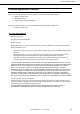
Chapter 3 Setup 3. 3. EXPRESSSCOPE Engine 3 EXPRESSSCOPE Engine 3 3.1 Overview EXPRESSSCOPE Engine 3 provides a variety of features using BMC (Baseboard Management Controller), which is a system management LSI. See EXPRESSSCOPE Engine 3 User's Guide for detailed information. EXPRESSSCOPE Engine 3 monitors the power supply unit, fans, temperature, and voltage of the server.
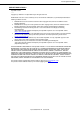
Chapter 3 Setup 3.2 3. EXPRESSSCOPE Engine 3 EXPRESSSCOPE Engine 3 Network Configuration Take the steps below to use EXPRESSSCOPE Engine 3 through the Web browser. 1. Run POST following Chapter 3 (1.1.1 POST sequence). Wait until the following message appears on the lower left of the screen. Press SETUP, Internal Flash Memory, ROM Utility, Network 2. Press the key while the message is being displayed to launch ROM Utility. 3.
Chapter 3 Setup 3. EXPRESSSCOPE Engine 3 5. On the following screen, select Enable when you use DHCP, or select Disable and specify IP Address (Required), Subnet Mask (Required), Default Gateway, and DNS Server when you do not use DHCP. Tips If Shared BMC LAN is enabled, Web feature, remote media/KVM feature, or command line interface feature may be interrupted. In this case, wait for a while, and connect with network again. When IPv4 Property is selected 6.
Chapter 3 Setup 4. 4. EXPRESSBUILDER EXPRESSBUILDER EXPRESSBUILDER helps you to install Windows or maintain the server. 4.1 Features of EXPRESSBUILDER EXPRESSBUILDER provides the following features. Features Descriptions Setup Installs Windows on your server. Easily completes the process from RAID (Windows reinstallation) configuration to installation of applications. To use this feature, select OS installation in the menu after boot.
Chapter 3 Setup 5. 5. Installing Software Components Installing Software Components Continue to install software components such as OS. See the instructions below.
Chapter 3 Setup 6. 6. Turning Off the Server Turning Off the Server Turn off the server by using the following procedure. If the power cord of the server is connected to a UPS, refer to the documentation supplied with the UPS or the documentation for the application controlling the UPS. 1. Shut down the OS. 2. The server automatically turns off after the OS shuts down. Confirm that POWER LED is OFF. 3. Turn off peripheral devices. Tips Hibernate function of Windows Server cannot be used.
4 NEC Express5800 Series Express5800/R120f-1M Appendix 124 1. Specifications 2. Interrupt Lines 3.
Chapter 4 Appendix 1. 1. Specifications Specifications N8101- N code CPU 768F CPU 769F 770F 773F 775F Intel ®Xeon® processor Clock speed Number of CPUs, standard / maximum Intel® Smart Cache (Last Level Cache) Number of cores (C) / Number of threads (T) per CPU Chipset E5-2603 v3 1.60GHz 1/2 15MB E5-2609 v3 1.90GHz 6C/6T E5-2620 v3 2.40GHz 6C/12T E5-2640 v3 2.60GHz E5-2650L v3 1.
Chapter 4 Appendix 1.
Chapter 4 Appendix 1. Specifications N8101- N code CPU 776F CPU 778F 779F 930F 931F Intel ®Xeon® processor Clock speed Number of CPUs, standard / maximum Intel® Smart Cache (Last Level Cache) Number of cores (C) / Number of threads (T) per CPU Chipset E5-2660 v3 2.60GHz 1/2 25MB E5-2670 v3 2.30GHz E5-2690 v3 2.60GHz E5-2695 v3 2.30GHz 30MB 35MB 10C/20T 12C/24T 14C/28T E5-2697 v3 2.
Chapter 4 Appendix 1.
Chapter 4 Appendix 1. Specifications N8101- N code CPU 932F CPU 933F Intel ®Xeon® processor Clock speed Number of CPUs, standard / maximum Intel® Smart Cache (Last Level Cache) Number of cores (C) / Number of threads (T) per CPU Chipset E5-2698 v3 2.
Chapter 4 Appendix 1.
Chapter 4 Appendix 2. 2. Interrupt Lines Interrupt Lines Interrupt lines are assigned as factory settings as shown below. Use this table as a reference when you add optional devices. • Interrupt lines As factory settings, interrupt lines are assigned as follows.
Chapter 4 Appendix 3. 3. Glossary Glossary Terms BIOS Setup Utility (SETUP) BMC Description Software for setting BIOS. You can run this software by pressing key during POST. Baseboard Management Controller (BMC) is a built-in controller that supports the IPMI version 2.0 protocol. BMC can manage the server hardware. BMC RESET Switch A switch for resetting the BMC of the server. This resets the BMC without clearing the BMC settings. Use the switch if the problem on the BMC occurs.
NEC Express Server Express5800/R120f-1M User’s Guide September 2014 NEC Corporation 7-1 Shiba 5-Chome, Minato-Ku Tokyo 108-8001, Japan ©NEC Corporation 2014 The contents of this manual may not be copied or altered without the prior written permission of NEC Corporation.