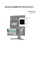
GammaCompMD QA Client Version 5 User Manual Version 5.1.
GammaCompMD QA Client User Manual Copyright © NEC Display Solutions Ltd. 2006 - 2015 This document contains proprietary information from NEC Display Solutions, Ltd. This information may not be reproduced or transmitted, in whole or in part, without a written agreement from NEC Display Solutions, Ltd. No patent or other license is granted to this information. The software, if any, described in this document is furnished under license agreement.
GammaCompMD QA Client User Manual Table of contents About GammaCompMD QA Client ............................................................................. 7 1. System Environment .......................................................................................... 10 1.1. Before you start ......................................................................................................10 1.2. Operating System Environment .......................................................................
GammaCompMD QA Client User Manual 3.2. Installation of the internal database .........................................................................30 3.3. Finishing the installation ..........................................................................................31 3.4. Options to consider during installation.....................................................................31 3.5. Un-installation .........................................................................................
GammaCompMD QA Client User Manual 7.3.4. Schedule Setup...................................................................................................... 89 7.3.5. Sensor Setup ......................................................................................................... 89 7.3.6. Historical Trend View ............................................................................................ 89 7.4. QA Test ............................................................................
GammaCompMD QA Client User Manual 7.7.4.3. Latest Results List ................................................................................................................................. 147 7.7.4.4. Display Information .............................................................................................................................. 148 7.7.4.5. System Information ..............................................................................................................................
GammaCompMD QA Client User Manual About GammaCompMD QA Client GammaCompMD QA is a Display Maintenance and Quality Assurance system specifically developed to maintain Diagnostic Imaging Displays in a Medical Environment and ensure compliance with Digital Imaging and Communications in Medicine Grayscale Standard Display Function (DICOM GSDF).
GammaCompMD QA Client User Manual Full network capability With various supported network protocols, NEC displays can be easily integrated and configured into a PACS network infrastructure. The GammaCompMD QA network system performs network communication between GammaCompMD QA Server and associated GammaCompMD QA Client workstations. These workstations can be either diagnostic imaging workstations or client clinical referral workstations as part of a PACS system.
GammaCompMD QA Client User Manual The Applications are called up from a taskbar icon, where a user - depending on user level checks display status, does calibrations, conformance tests, QA tests or visual tests. The three most important System Services are: The QAEngine Service Communicating with the connected displays and sensors, the Applications, the Database Service and - when connected - with the GammaCompMD QA Server.
GammaCompMD QA Client User Manual 1. System Environment 1.1. Before you start This manual contains instructions for using GammaCompMD QA Client software. GammaCompMD QA Client is designed to run in the following operating environment. Please check the system environment before installing GammaCompMD QA Client software. 1.2.
GammaCompMD QA Client User Manual i1Pro by X-Rite (USB) Spyder3 by Colorvision (USB) Konica Minolta CA-210 (RS-232C/USB) IBA LXplus (RS-232C) - Color measurement not supported Unfors Luxi (RS-232C) - Color measurement not supported IBA LXcan(USB) - Color measurement not supported IBA LXchroma(USB) 1.6. Pre-requisite Software Adobe Reader (Version 7.0 or later) – To display the Help file An internet browser – To read exported QA Test HTML files (i.e.
GammaCompMD QA Client User Manual NEC MD Series (Color) MD21M MD304MC MD301C4 MD322C8 NEC MD Series (Display Sensor Model / Color) MD212MC MD213MC MD210C2 MD211C2 MD242C2 MD210C3 MD211C3 MD302C4 MD302C6 (USB cable required) NEC EA Series EA193Mi EA224WMi EA234WMi EA244WMi EA244UHD EA273WMi EA274WMi EA275WMi EA275UHD EA294WMi EA304WMi EA305WMi NEC MultiSync PA Series PA231W PA241W PA271W PA301W PA242W PA272W PA302W PA322UHD NEC MultiSync P Series P241W P232W Copyright © NEC Display Solutions Ltd.
GammaCompMD QA Client User Manual P242W NEC Public Display Series (For displaying medical images) X651UHD X841UHD X981UHD NEC large format models Multeos M40 Multeos M46 Note: Gamma correction only, manual adjustment of luminance is Multeos LCD M401 required LCD 4620 Multeos LCD M461 LCD 4020 LCD 5220 LCD 6520L LCD 6520P LCD X461UN LCD X461HB LCD P401 LCD P461 LCD S401 LCD S461 LCD S521 LCD P521 LCD P402 *Using DVI connection only LCD P462 *Using DVI connection only Copyright © NEC Display Solutio
GammaCompMD QA Client User Manual 2. Checking System Dependencies 2.1. External Sensors External sensor drivers are included with the GammaCompMD QA Client. Please install GammaCompMD QA Client before connecting any external sensor to the system. If multiple external sensors are connected simultaneously, they will not be correctly identified. Please connect only one external sensor. 2.2.
GammaCompMD QA Client User Manual 2.6. Using the IBA LXcan or LXchroma instrument For ambient light measurement, the optional LxLs lux sensor needs to be attached to the LXcan or LXchroma instrument. Please turn the LXcan or LXchroma power to OFF when attaching / detaching the Lux sensor. Please refer to detailed instructions how to use this instrument in the LXcan or LXchroma user manual. The screen contact mask is needed for measuring directly on screens.
GammaCompMD QA Client User Manual 2.10. Calibration, Test, Level Measurements, and QA Testing Do not turn off power, enter the power management manually (from OS side), unplug cables, or remove external sensors’ USB cables during calibration, conformance test, uniformity test, white/black level measurements or QA tests, as doing so will have a negative effect on accuracy. If re-initialization is necessary, follow the instructions in 7.7.1.1 Re-initialization of Display Configuration (page 105). 2.11.
GammaCompMD QA Client User Manual 2.15. Using NEC X651UHD/X841UHD/X981UHD If GCMDQA has not recognized the NEC model X651UHD, X841UHD and X981UHD, check the following using the ON-SCREEN-DISPLAY (OSD) menu of this large format display SPECTRAVIEW ENGINE is’ ON’. DDC/CI is ’ENABLE’. (Refer to the display's documentation for details.) 2.16. Using NEC MD212G3 When using the MD212G3 model, connecting a USB cable from the computer to the monitor is required for communication. 2.17.
GammaCompMD QA Client User Manual (2) (3) (4) (5) Uninstall GammaCompMD QA. Upgrade to Windows 8 / 8.1. Re-Install GammaCompMD QA. Restore Backup data. Refer to 7.7.1.2 Reinitialize System Configuration (page 108). If restoring backup data (history) is not desired, only perform step (2), (3) and (4). GammaCompMD QA Client performs as Desktop Application. If Start Screen (Figure 2) and/or Modern UI Application (Windows Store apps) are shows, the execution of network and/or schedule tests are suspended.
GammaCompMD QA Client User Manual Dialog boxes with only an OK button Clicking OK closes the dialog box. When displaying a dialog box with display selection buttons again, the previous selections are cleared. Make the selections again. Dialog boxes with OK and Cancel buttons Clicking OK performs the intended action (enables setting / start calibration / view report). Clicking Cancel closes dialog box without applying any changes.
GammaCompMD QA Client User Manual displayed on one screen. Set up the input sequence, screen order in Windows and the display area according to the example settings shown on the next page. Copyright © NEC Display Solutions Ltd.
GammaCompMD QA Client User Manual Examples for correct setup Screen order in Windows setting view and actual display screen should be the same.
GammaCompMD QA Client User Manual When you perform a calibration, luminance measurement or QA test, PIP MODE will be turned off automatically. You can test the correct input, using the following: 1. Manually turn “PIP MODE” OFF on the display via control button. 2. For case (a), (c), (e) and (f), you should only see the image of display area #1, otherwise changes in connection sequence are required. For case (b) and (d), change some settings to see the image of display area #2 image as well. 3.
GammaCompMD QA Client User Manual If the main screen setting is correctly done, Sensor Contact Position Guide (Figure 57) will be shown before calibration or taking other measurements starts. If QA Test starts, the following message (Figure 5) will be shown before calibration or taking other measurements starts. When the circle and the rectangle are displayed correctly related to the center of screen, the user is allowed to continue the operation.
GammaCompMD QA Client User Manual IMPORTANT NOTES: ・Unlike other sensors, retractable sensor executes calibration automatically when connected to the system. As long as PIP MODE main screen setting is correctly done, calibration will be completed properly without showing Sensor Contact Position Guide (Figure 57) or Continue Operation dialog (Figure 5). If the screen is not correctly set, calibration will stop with an error message. Please set up PIP MODE correctly again and re-execute the calibration.
GammaCompMD QA Client User Manual ・If the operation with the PIP MODE (PbP) goes wrong, connect the PC with the display using an USB cable. This is an alternative way of communication between PC and Display. Refer to the display's documentation for details. ・If the restoration of PIP MODE (PbP) from OFF to ON takes unusually long time, connect the PC with the display using an USB cable. Refer to the display's documentation for details.
GammaCompMD QA Client User Manual 3. Installation Administrator privileges are required in order to install this software. If the user does not have administrator rights, a prompt will appear requesting an administrator’s username and password. Follow the on-screen instructions to continue with the installation. Selecting Only for me in Select Options dialog box (Figure 8) will set the input ID as the current user and a desktop shortcut will be created for the [Administrator] account.
GammaCompMD QA Client User Manual 3.1. Setup NOTE: If GammaCompMD Version 2 or GammaCompMD QA Version 3 Client is still installed on the system, these need to be un-installed manually before this setup. When installation begins, a Choose Setup Language (Figure 7) and then an Options Selection (Figure 8) dialog box will be displayed. Follow the instructions accordingly for any other dialog boxes that may appear. In addition, a Readme file is shown. After reading the contents, click on the x to exit.
GammaCompMD QA Client User Manual Options Selection Figure 8: Options Selection dialog box This box is available to select the following installation options. Creation of desktop shortcuts Display Maintenance / Quality Assurance / Show Test Pattern) QA Standard Setup (AAPM TG18 / ACR AAPM SIIM / JESRA X-0093) Create shortcut in Start Menu (Start Menu / Startup Menu) Start of System Service (Automatically / Manually) NOTE: System Service refers to installed Windows System Services.
GammaCompMD QA Client User Manual Install this application (Anyone who uses this computer (all users) / Only for me) Install to folder: By default, GammaCompMD QA will be installed in the following folder: Windows 32-bit versions C:\[Program Files]\NECDS\QA_Client Windows 64-bit versions C:\[Program Files(x86)]\NECDS\QA_Client NOTE: In the following, this user manual refers to these folders as [Installation Folder].
GammaCompMD QA Client User Manual 3.2. Installation of the internal database During the installation process, GammaCompMD QA also installs a PostgreSQL database, as shown in Figure 10. Figure 10: Database installation in progress… This database is used to save all calibration actions, measurement data, QA tests and alerts and to build a history of the status of the connected display over time.
GammaCompMD QA Client User Manual 3.3. Finishing the installation A dialog box will appear indicating the installation has finished, Installation Complete dialog box (Figure 11) is displayed. Figure 11: Installation Complete dialog box 3.4. Options to consider during installation Backup User Account GammaCompMD QA Client automatically creates the following account: "GCMDQABackupUser” account for backup features [WARNING] Do not edit the account. malfunction.
GammaCompMD QA Client User Manual GammaCompMD QA Client installation. If this dialog is displayed, click on the Continue button. Figure 12: Software Installation confirmation dialog 3.5. Un-installation This application can be un-installed in two different ways: Using the Windows Control Panel Windows XP: [Start Menu] [Control Panel] [Add or Remove Programs] and double-click on GammaCompMD QA Client to un-install.
GammaCompMD QA Client User Manual Figure 13: Backup confirmation Click Yes to create a backup. Click No to continue without making a backup. Backed up files are saved as follows: Windows XP: C:\[Documents and Settings]\[ALL Users]\[Documents] Windows 7 and windows 8 / 8.1: C:\[Users]\[Public]\[Documents] NOTES: The backup filename is created in the following format: [Computer Name] Year Month Day Hour Minute Second.gcmddat Example: The filename for a backup made at 1:15:30 p.m.
GammaCompMD QA Client User Manual NOTE: If you connected a NEC display that is not supported by GammaCompMD QA, it will be recognized as "StdDisplay". In that case, Initial target luminance will be set to 200cd/m2, and the grade of quality assurance test will be set to match to the target luminance. If this display is supported by a future version of GammaCompMD QA and you install this new version as an upgrade, the following configuration information will be kept.
GammaCompMD QA Client User Manual 4. Firewall Settings An active firewall may block network communication between a GammaCompMD QA Client and a GammaCompMD QA Server, if a firewall is enabled. The following description refers to the integrated firewall within Windows. 4.1. Windows XP Opening the Windows Firewall Click [Start] on the task bar, then click [Control Panel] [Windows Firewall]. The [Windows Firewall] screen is displayed.
GammaCompMD QA Client User Manual Setting Firewall Exceptions Select the [Exceptions] tab on the [Windows Firewall] screen. The [Windows Firewall Exception Program List] menu, see Figure 17, is shown. If QAInitialize and QAEngineService have already been added to the Exception Program List, the following procedure is unnecessary. If it has not yet been added, click [Add a Program]. The [Add a Program] menu, see Figure 15, is displayed. Click [Browse]. The [Browse] menu, see Figure 16, is displayed.
GammaCompMD QA Client User Manual Figure 16: Browse programs to add Figure 17: Windows Firewall - Exceptions program list Copyright © NEC Display Solutions Ltd.
GammaCompMD QA Client User Manual Setting Firewall Advanced Select the [Advanced] tab on the [Windows Firewall] screen. The [Windows Firewall – Advanced], see Figure 18, is shown. Choose from a [Network Connection Settings] list the connection used for communication with a server, and click a [Settings…] button. Figure 18 Windows Firewall – Advanced Select the [ICMP] tab on the [Advanced Settings] screen, see Figure 19, is shown. Select tick box [Allow incoming echo request], and click a [OK] button.
GammaCompMD QA Client User Manual 4.2. Windows 7 and Windows 8 / 8.1 Opening the Windows Firewall Click on [Start] in the taskbar, and select [Control Panel].(Windows 7) The [windows key] and the [X key] are pressed simultaneously, and select [Control Panel].(Windows 8 / 8.1) Click on [System and Security] [Windows Firewall]. The [Help protect your computer with Windows Firewall] menu, see Figure 20, will appear.
GammaCompMD QA Client User Manual Figure 21: Customize settings for each type of network Setting Firewall Exceptions Click on [Allow a program or feature through Windows Firewall] on the left side of this menu, see Figure 20. The [Allowed programs to communicate through Windows Firewall] menu, see Figure 24, is displayed. If QAInitialize and QAEngineService are already added, the procedures below are unnecessary. If it is not added, click on [Allow another program…].
GammaCompMD QA Client User Manual Figure 22: Add a Program menu Figure 23: Select (Browse) programs to add screen The Menu, as shown in Figure 24, allows programs to communicate through the Windows Firewall. Verify that the QAInitialize and QAEngineService are checked. Copyright © NEC Display Solutions Ltd.
GammaCompMD QA Client User Manual Figure 24: Allow programs to communicate through Windows Firewall Screen Inbound Rules of the Firewall Click [Advanced Setting] on the left side of the [Help protect your computer with Windows Firewall] menu, see Figure 20. The [Windows Firewall with Advanced Security] menu, see Figure 25, will now be shown. Copyright © NEC Display Solutions Ltd.
GammaCompMD QA Client User Manual Figure 25 Windows Firewall with Advanced Security Select [Inbound Rules] from the tree on the left, and select [File and Printer Sharing (Echo Request - ICMPv4-In)] and [File and Printer Sharing (Echo Request – ICMPv6-In)] in the center pane.
GammaCompMD QA Client User Manual 5. First Start 5.1. Start-up and shutdown of GammaCompMD QA Client If you selected Create shortcut in Startup folder during installation, GammaCompMD QA Client is started automatically when you start Windows. If you do not have created a shortcut on the Startup menu or the user have terminated GammaCompMD QA Client manually, please select GammaCompMD QA Client in the startup menu then active GammaCompMD QA Client manually.
GammaCompMD QA Client User Manual 5.2. User Password Setup As shown in User levels, GammaCompMD QA Client provides the following three user levels: Advanced Mode Display Maintenance (Expert level) Technician Mode Quality Assurance (Standard level) Radiologist Mode Show Test Patterns (Visual test level) The functionality is different for each level. By default, all users can execute operations at all levels from Advanced to Radiologist without a password, as no passwords are initially set.
GammaCompMD QA Client User Manual Figure 27: User authentication dialog 5.3. Changing the Display Configuration If the screen orientation, resolution, logical display position, the number of connected displays or PIP MODE has changed, the Reinitialize Display Configuration is required. See 7.7.1.1 Re-initialization of Display Configuration (page 105) for the re-initialization procedure. 5.4. Changing the Sensor When clicking on Auto-Detect, the sensor connection is recognized.
GammaCompMD QA Client User Manual 6. Main Display ③ ① ④ ② ⑤ Figure 28:Main Display and each Information Area ① Main Menu Area The contents of ④Display Information Area and ⑤Sub Menu will change by selecting each item of the main menu. ② User Level Area The current User Level is shown. The User Level will change by selecting a User Level in the listbox. You will be prompted to enter the password if a User Password has been set for this level.
GammaCompMD QA Client User Manual A grayscale display is being used in landscape mode A grayscale display is being used in portrait mode A large screen display (example: Multeos) is being used in landscape mode A large screen display (example: Multeos) is being used in portrait mode A navigation display (a display that is not subject to any action) is being used in landscape mode A navigation display (a display that is not subject to any action) is being used in portrait mode The display is recognize
GammaCompMD QA Client User Manual 7.
GammaCompMD QA Client User Manual Uniformity Test Display Matching Create Modification Log Entry Display Control Button Lock Special Reports White and Black Luminance Measurement Reports Uniformity Test Reports Latest Results List Display Information System Information Help - 7.1. Display Overview Click Display Overview in the Display Maintenance screen to display Figure 29. The Display Overview screen is shown. Figure 29: Display Overview screen Copyright © NEC Display Solutions Ltd.
GammaCompMD QA Client User Manual 7.1.1. Rearrange Displays Click Rearrange Display in Display Overview to display the Rearrange Display dialog box. Figure 30: Rearrange Display dialog box Display Arrangement You can rearrange a display by dragging and dropping with the mouse (always from left to right) in the Display Arrangement. Please use this function to rearrange the information that is displayed in the display information area.
GammaCompMD QA Client User Manual Backlight Brightness Alert See 7.7.1.5 Alert Setup (page 116) for a description of the error or alert. One of the following errors did occur: (Flashing Orange) White Luminance Test Error LUM Test Error FIT Test Error GSDF Error QA Test Error See 7.7.1.5 Alert Setup (page 116) for a description of the error. Normal status without any alerts. (Green) The display is not enabled in Windows, or the interface mode is set (Gray) to NAVDisplay. See 7.7.1.
GammaCompMD QA Client User Manual 7.1.5. Conformance Test Reports Click Conformance Test Reports in Display Overview to show results of conformance tests which were performed in the past. See 7.3.3 Conformance Test Reports (page 85). 7.1.6. QA Test Reports Click QA Test Reports in Display Overview to show results of QA tests which were performed in the past. See 7.4.3 QA Test Reports (page 95). Copyright © NEC Display Solutions Ltd.
GammaCompMD QA Client User Manual 7.2. Calibration Click Calibration in the Display Maintenance screen to display Figure 31. The Calibration screen is shown. Figure 31: Calibration screen 7.2.1. Perform a Calibration Select the display to select the check box at the top of the display icons (Multiple displays can be selected.). And then click Start Calibration at the bottom right of this screen, the calibration will start for the selected display(s). Please follow the instructions on the screen.
GammaCompMD QA Client User Manual Figure 32: Status screen on target display calibration Once a calibration is completed, a Calibration Report dialog box is shown on each target display, as shown in Figure 33. See 7.2.3 Calibration Reports (page 56). Figure 33: Calibration Report dialog box NOTE: - When the target curve Native was selected, a grayscale calibration will not be performed. Only the native luminance response curve of the display will be measured.
GammaCompMD QA Client User Manual - A calibration may not be performed when using an external sensor without color support. Please refer to Using sensor models without color measurement capability in 7.2.6 Sensor Setup (page 77). - Additional considerations for details. - The PICTURE MODE in the ON-SCREEN-DISPLAY (OSD) of some display models will be changed from its factory preset mode to “GCMDQA” after a calibration. There are cases that this factory preset status will not be overwritten.
GammaCompMD QA Client User Manual CSV Export button OK button Shows Save Report in CSV Format dialog box. Reports can be saved as a CSV file. Show the Calibration Report dialog box for the display selected, see Figure 34. Summary(tab) Display the Calibration Report: Summary dialog box. The list contains the following items: Operator Name, Display Model, Display Serial Number, Sensor Model, Sensor Serial Number, ICC Profile and Result (Successful/Failed).
GammaCompMD QA Client User Manual Figure 36: Calibration Report: White Luminance dialog box Grayscale Characteristic (tab) The list contains the following items: Display Function, Number tab of Measurement Points, Maximum Luminance Actual (cd/m2), Minimum Luminance Target (cd/m2), Minimum Luminance Actual (cd/m2), Maximum DDL Value, Number of LUT Entries and Maximum LUT Value.
GammaCompMD QA Client User Manual Figure 38: Calibration Report: Display Function dialog box Copyright © NEC Display Solutions Ltd.
GammaCompMD QA Client User Manual 7.2.4. Schedule Setup Click on Schedule Setup in Calibration to display the Schedule Setup dialog box, see Figure 39. NOTE: Scheduled action can use not only Display Sensor but also External Sensor. Display Sensor will be used preferentially regardless of the Preferred Sensor Selection Settings. See 7.2.6 Sensor Setup (page 77) If the display has no Display Sensor, External Sensor will be used.
GammaCompMD QA Client User Manual Figure 39: Schedule Setup dialog box Schedule List (Time Table) At initial state, this list is empty. After schedules have been defined, the first schedule will be displayed on top of the list, with next schedules underneath, in order of date and time. Add button Shows the Add new schedule dialog box Figure 40 to add scheduled tasks as well as start date and interval. Figure 40: Add new schedule dialog box ・ Interval Copyright © NEC Display Solutions Ltd.
GammaCompMD QA Client User Manual Set the frequency with which the schedule will be executed (days, weeks, months, years). Enter a number from 1 to 1000. Example: If “6 months” is selected, the schedule will be executed on the schedule start date and then every 6 months after that. ・ Day or Date A preferred day of the week or month can be set for the next schedule execution date onwards. Date of Month cannot be used for daily or weekly settings.
GammaCompMD QA Client User Manual Figure 41: Edit saved schedule dialog box ・ OK button Closes the dialog box and saves any changes to the schedule. Check the changes in the Schedule Setup dialog box on (Figure 39). ・ Cancel button Closes the dialog box without applying any settings. Delete button Click on the schedule which you wish to delete. Then click the Delete button. Multiple schedules cannot be deleted at once. OK button Closes the Schedule Setup dialog box.
GammaCompMD QA Client User Manual 7.2.5. Calibration Setup When Calibration Setup is clicked within the Calibration main menu, the Calibration Setup dialog box, shown in Figure 42, is displayed. This dialog box is used to define parameters and various settings for each display which are used during the calibration. Since the actual calibration operation is executed sequentially, with White luminance calibration first, followed by Grayscale calibration, these settings are required before a calibration.
GammaCompMD QA Client User Manual Luminance value do not return to an original value even if cancel button is clicked. Manually adjust the Reflected Luminance value button(Figure 51) OK button of Reflected Luminance Setup(Figure 52) Retrieve both factory preset values from the display button(Figure 51) Measure and calculate button(Figure 51) Apply button Applies the calibration parameter settings to each display but does not close the dialog box.
GammaCompMD QA Client User Manual Color Temp and Chromaticity Target (x,y) Shows the target color temperature (K) and color chromaticity (x, y), when executing calibration. The optimum value is displayed according to the selected calibration mode and depend on the display model. If an individual color temperature or chromaticity target (x,y) setting is required, click the Edit button. The Custom Chromaticity dialog box, as shown in Figure 43, will be displayed.
GammaCompMD QA Client User Manual Chromaticity Feedback Enable or disable the chromaticity feedback feature, which runs independently after a calibration has finished. This option is grayed out for display models which do not support this feature. Copyright © NEC Display Solutions Ltd.
GammaCompMD QA Client User Manual Grayscale Function Figure 44: Calibration Setup – Grayscale dialog box Number of Measurement Points for Calibration Select the number of measurement points for measuring the luminance characteristics of the display during a grayscale calibration. When a Display Sensor was selected, the selected number of measurement points here is ignored. NOTE: The number of measurement points may not be selectable, depending on display model.
GammaCompMD QA Client User Manual Display Function The display function can be selected from the following four types ・ Native When Native is selected as the target curve, a grayscale calibration is not performed. The luminance characteristics of the display are only measured. ・ Gamma Curve Value Fixed Gamma correction values from 1.00 to 3.00 may be selected. ・ DICOM GSDF Default setting for DICOM Grayscale Standard Display Function calibration (DICOM Standard, Part 14). Values from 0.50 to 1.
GammaCompMD QA Client User Manual Import button (mostly disabled) When the Import button is clicked, the Import Custom Curve Points Text File dialog box, as shown in Figure 46, is displayed. Figure 46: Import Custom Curve Points Text File dialog box Minimum Black Level tab When the Minimum Black Level tab is clicked, the minimum black level setup dialog box, as shown in Figure 47, is displayed. When the checkbox is checked, the minimum black level can be set within a range from 0.00 to 4.99 cd/m2.
GammaCompMD QA Client User Manual NOTE: This function is useful to lift the black level and make the dark portions of a typical DICOM image more visible against reflections of the ambient light on the LCD panel of a display. Due to this reason, regional/national obligations as well as recommendations from clinical studies may require raising the black level of diagnostic imaging displays. Calculate from Contrast Ratio button Displays the Custom Black Luminance Level dialog box, as shown in Figure 48.
GammaCompMD QA Client User Manual Figure 50: Ambient light measurement successful NOTE: External sensors which can measure ambient light are i1 Display2, ColorMunki, i1 Pro, Spyder3, i1Display Pro, LXPlus, Luxi, MD-N2M5B, LXcan or LXchroma. Please make sure to connect the external sensor and test the connection. Please refer to 7.2.6 Sensor Setup (page 72) for correct sensor selection and connection test.
GammaCompMD QA Client User Manual Use/Don’t use Ambient Light Compensation Select between Don’t use Ambient Light Compensation or Use Ambient Light Compensation. Ambient Light Compensation is active during Calibrations, Conformance Tests, White/Black Luminance Measurements and Uniformity Tests. Illumination Shows the value of illumination (ambient light, unit: lux) as measured by the display’s ambient light sensor at time of installation.
GammaCompMD QA Client User Manual Retrieve both factory preset values from the display The initial factory shipment value of the Diffuse Reflection coefficient is transferred from the display. The reflected luminance value is then calculated using the Illuminance value measured by the ambient light sensor of the display. The formula is: Reflected luminance = Illuminance x Diffuse Reflection coefficient Example: 0.04 cd/m2 = 20 lux x 0.002 cd/m2 per lux.
GammaCompMD QA Client User Manual measuring”) is required to measure the reflected luminance of the screen surface of a display – with the display’s power switched OFF and a clean surface. ・ The last Diffuse Reflection coefficient value uploaded to the display is used to compensate ambient light changes by correcting the DICOM curve in the display. ・ When using MD215MG, MD211G5, MD212G3 or MD302C6, run the calibration after setting Ambient Light Compensation.
GammaCompMD QA Client User Manual rights, an ICC profile will not be created. Also depending on the workstation environment, the ICC profile may not be recognized automatically by the Windows Color Management System (CMS). In this case, you need to set it up manually. NOTE: For most current applications in the medical environment, an ICC profile is not required, therefore this box may usually be unchecked.
GammaCompMD QA Client User Manual Source of primary color chromaticity values for ICC Profile Select from the following three options for the value to use when creating the ICC profile. ・ Automatic When creating the ICC profile, a suitable value is automatically selected between sensor measurement values and measured values from the factory. ・ Calibration sensor measurements Use the values of the sensor to create the ICC profile. ・ Factory data Use the values from the factory to create the ICC profile. 7.
GammaCompMD QA Client User Manual NOTE: For scheduled execution or test from the network, the display sensor is used regardless of the sensor selection. When a display sensor is used with a wide format display, be sure to set the EXPANSION mode to “FULL” in the OSD of the display. Figure 55: Preferred Sensor Selection Listbox Display Sensor Selection If a display with integrated front sensor is selected, the model name of the display is shown.
GammaCompMD QA Client User Manual Reference Calibration is used to re-adjust either the integrated front sensor of a display or a MD-N2M5B mounted on top of the display. To re-adjust a display sensor, both the display sensor and an external sensor need to be connected. Click the Reference Calibration button and perform the re-adjustment by following the displayed messages.
GammaCompMD QA Client User Manual External Sensor Selection The external sensor can be selected from the External Sensor Selection listbox, as shown in Figure 56. NOTE: Only one external sensor is supported at time and it will be the last selected sensor model. Figure 56: External Sensor Selection Listbox Auto-Detect button Clicking on this button allows the external sensor to be automatically detected, even if a sensor was not yet selected from the External Sensor Selection listbox described above.
GammaCompMD QA Client User Manual A LCD display is fragile and may be damaged if the external sensor is forcefully pressed against it. Never attach a sensor with suction cups to the display. Always use the supplied cable and suspend the sensor with a weight so that the sensor is stationary in front of the display. If the external sensor is separated from the screen during calibrations or tests (i.e. by falling off), the process may fail.
GammaCompMD QA Client User Manual Sensor selection rules External sensors cannot be used for all calibration operations. For scheduled display calibrations or remote calibrations and DICOM conformance tests, only a display sensor is appropriate. On the other hand, some external sensor models are unable to be used for Display Quality Assurance (QA), depending on regional / national regulations.
GammaCompMD QA Client User Manual 7.3. Conformance Tests Click Conformance Tests in the Display Maintenance screen to display Figure 59, Conformance Test screen is displayed. Figure 59: Conformance Test Screen 7.3.1. Perform a Conformance Test Tick the check box above the display icons to select the display. Multiple displays may be selected. Then click on Start Conformance Test at the bottom right of this menu. The conformance test will start for the selected display(s).
GammaCompMD QA Client User Manual After a Conformance Test has completed, the Conformance Test Report dialog box (Figure 61) and the White & Black Luminance Measurement Report dialog box (Figure 62) are shown on each display. Figure 61: Conformance Test Report dialog box Figure 62: White & Black Luminance Measurement Report dialog box Copyright © NEC Display Solutions Ltd.
GammaCompMD QA Client User Manual 7.3.2. Rearrange Displays Click Rearrange Display in Conformance test to rearrange display. See 7.1.1 Rearrange Display (page 51). 7.3.3. Conformance Test Reports Click Conformance Test Reports in Conformance test to display the Conformance Test Reports dialog box, see Figure 63. NOTE: Conformance test reports are shown based on a DICOM standard Grayscale Display Function (GSDF).
GammaCompMD QA Client User Manual Summary tab Shows the Conformance Test Report: Summary dialog box, see Figure 64.
GammaCompMD QA Client User Manual Luminance Level tab Shows the Conformance Test Report: Luminance Level Dialog box, see Figure 65. The luminance value of each gray scale is displayed. Figure 65: Conformance Test Report: Luminance Level dialog box Graph tab Shows the Conformance Test Report: Graph dialog box. Figure 66: Conformance Test Report: Graph dialog box Copyright © NEC Display Solutions Ltd.
GammaCompMD QA Client User Manual Graph JND per DDL Contrast Response JND per DDL Contrast Response Shows a graph of the JND interval per DDL calculated from the luminance characteristics after calibration in the conformance test. Shows a contrast response graph calculated from the luminance characteristics after calibration in the conformance test. The contrast response graph is a logarithmic base 10 representation. The graph shows JND per DDL for a selected Execution Date.
GammaCompMD QA Client User Manual Primary Colors tab Shows the Conformance Test Report: Primary Colors dialog box, see Figure 67. This shows the CIE x and y values measured for each primary color (red, green and blue). Figure 67: Conformance Test Report: Primary Colors dialog box 7.3.4. Schedule Setup Click Schedule Setup in Conformance Test to list and modify schedules, if required. See 7.2.4 Schedule Setup (page 60). 7.3.5.
GammaCompMD QA Client User Manual 7.4. QA Test Click QA Test in the Display Maintenance to display Figure 68, QA Test screen is displayed. Figure 68: QA Test screen 7.4.1. QA Test Start Click Start QA Test to display Select Target Display(s) for QA Test dialog box, as shown in Figure 69. Verify that the Standard at the top left is correct. If not correct, change the test standard with 7.4.4 QA Test Setup (page 97). You can click OK button after entering the Tester Name.
GammaCompMD QA Client User Manual Select the type of test to be performed. The selection varies with the selected QA standard.
GammaCompMD QA Client User Manual The QA Test dialog box (Figure 71) will be shown on the upper left of the selected display when you click on the OK button. In case of ACR AAPM SIIM (2012), it will show the QA Test dialog box (Figure 72). Please continue the operation if Standard and Type of Test are correct. Figure 71: QA Test dialog box Figure 72: QA Test dialog box for ACR AAPM SIIM QA tests ・ Environment button Opens the Image Processing Environment dialog box.
GammaCompMD QA Client User Manual ・ Image Generator Select the type (CT/MR/PACS) from the listbox. If required for documentation, enter the manufacturer and model name of the Image Generator. ・ Connection Check the applicable connection status. In most cases, it will be a connection to a PACS workstation. Visual Test button Starts the visual test part of the QA test. Follow the instruction in the QA Visual Test Verification dialog box and visually verify the screen.
GammaCompMD QA Client User Manual AAPM TG18 (2005) Primary Class Min. 170 cd/m2 AAPM TG18 (2005) Secondary Class Min. 90 cd/m2 ACR AAPM SIIM (2012) Mammography Min. 420cd/m2 ACR AAPM SIIM (2012) Diagnostic Min. 350cd/m2 ACR AAPM SIIM (2012) Secondary Min. 250cd/m2 JESRA X-0093 Grade 1 Min. 170 cd/m2 JESRA X-0093 Grade 2 Min. 100 cd/m2 Select the appropriate one for the display under test. Refer to 15 Appendix for the category of ACR AAPM SIIM (2012).
GammaCompMD QA Client User Manual Figure 75: Warning dialog box 7.4.2. Rearrange Displays Click Rearrange Display in QA Test to rearrange display. See 7.1.1 Rearrange Display (page 51). 7.4.3. QA Test Reports Click QA Test Reports in QA Test to display the QA Test Report Display Selection dialog box.
GammaCompMD QA Client User Manual Figure 77: QA Test Report dialog box Figure 78: QA Test Report dialog box (if Monthly box is checked) Copyright © NEC Display Solutions Ltd.
GammaCompMD QA Client User Manual ・ Reports Listbox If the listbox in the bottom left hand corner of the dialog box is clicked, the latest report will be displayed at the top with previous reports underneath in order of date and time. Click the date you wish to view and that day’s content will be displayed. ・ HTML Export button Reports will be saved in HTML file format. ・ CSV Export button Report will be saved in CSV file format. ・ OK button Closes the dialog box. 7.4.4.
GammaCompMD QA Client User Manual EU Limited Edition only: If you are using GammaCompMD QA Client for EU and selected QAXRAY (IEC 62563-1/DIN V 6868-57/DIN 6868-157) during the installation, the QAXRAY QA test routine is started when executing QA tests. These tests and the visual representation differ from the above-mentioned menus and dialog boxes. Please refer to the Help file which is displayed by pressing the "?" button on the QAXRAY start menu for details. Copyright © NEC Display Solutions Ltd.
GammaCompMD QA Client User Manual 7.5. Test Pattern Click Test Pattern in the Display Maintenance menu to display Figure 80. The Test Pattern submenu is shown. Figure 80: Test Pattern screen 7.5.1. Display the Test pattern Click Show Test Pattern to open the Select target display(s) for Test Pattern Viewing dialog box. Figure 81: Selected display(s) for Test Pattern Viewing screen Select one or more displays and click the OK button to display the Show Test Pattern dialog box, as shown in Figure 82.
GammaCompMD QA Client User Manual Figure 82: Show Test Pattern dialog Clicking View button right of each Image opens a full screen test pattern on the target display, with the filename as indicated in the image file field. The Show Test Pattern dialog box is shown on the target display as well. NOTE: By default, the image file name field for Image 2 is empty (not defined). To include, add, or change Image 1, set the file name as described in 7.5.3 Test Pattern Setup (page 100).
GammaCompMD QA Client User Manual Figure 84: Edit Test Image Selection dialog box ・ No Image radio button Click to select no image. ・ Image created by test pattern generator radio button Select an image file from those in the listbox on the right. ・ Image File radio button The list of file names below the dialog is a list of visual test images. ・ Add button After copying a file into the above folder and selecting it, click the Open button to return to Figure 84 (page 101).
GammaCompMD QA Client User Manual 7.6. Stand Alone Calibration Stand Alone Calibration can recalibrate the display without a computer, using the integrated front sensor. When you start the Main Screen of GammaCompMD QA Client, the results of the Gamma Adjust and/or the DICOM Measurement function inside the display, which were created during a Stand Alone calibration, will be imported into the database of GammaCompMD QA.
GammaCompMD QA Client User Manual Figure 86: The result of DICOM Measurement Using this function: If you want to enable this function, the following actions are required: (1) Unzip the GammaCompMD QA package into a local or network hard disk folder, from where the installation will be started. (2) Open the StandaloneCalibration.ini file in the same folder as the installer setup.exe with a text editor. (3) Change the value of the line StandAloneCalibration=0 into StandAloneCalibration=1 and save the file.
GammaCompMD QA Client User Manual NOTES: ・ Do not perform a Stand Alone Calibration when you are using the Main Screen of GammaCompMD QA Client at the same. The results may be corrupted. ・ If the Stand Alone Calibration has a timestamp which is newer than the system time, a warning dialog (Figure 87) is displayed when the Main screen of GammaCompMD QA Client is opening. The results of the Stand Alone Calibration cannot be imported. Repeat the Stand Alone Calibration and enter the correct time.
GammaCompMD QA Client User Manual 7.7. Administrator Figure 88: Administrator screen 7.7.1. System Setup 7.7.1.1. Re-initialization of Display Configuration In Figure 89, the Initialize Display Configuration dialog box is displayed. Confirm that the display arrangement and the display interface mode are set properly. Figure 89: Initialize Display Configuration dialog box Copyright © NEC Display Solutions Ltd.
GammaCompMD QA Client User Manual Display Arrangement The displays shown in Display Arrangement may be dragged and dropped - always from left to right - to change the display arrangement. Use this method to re-arrange the logical display configuration in order to match the physical display arrangement on the work desk. Display Interface Mode This is used to classify each display. Three Display Interface Modes are available: NECDisplay: A NEC display which is fully managed and targeted for calibration.
GammaCompMD QA Client User Manual Figure 90: Example of a non-standard Display Arrangement in Windows NOTE: If Asset IDs were entered for the previously connected displays, these will be re-initialized. The Asset ID field for each display in the Display Information Area is shown blank. OK button Saves the settings and closes the dialog box. If no Operator Name is entered, this button is inactive. Cancel button Closes the dialog box without saving any settings.
GammaCompMD QA Client User Manual In case of confusion, the Automatic Configuration feature may be used to restore the original settings and then to start the tests again with a defined display arrangement. NOTE: The Automatic Configuration function cannot detect whether one of the connected displays is the Navigation or RIS monitor of a PACS system. Any display which cannot be detected as a NECDisplay will automatically be shown as a NAVDisplay.
GammaCompMD QA Client User Manual Figure 92: Initialize System Configuration dialog box This dialog box is used to set up Database Service, System Service and Event Logger Server as well as to restore database content that was backed up when the GammaCompMD QA Client system was un-installed. Starting System Service also enables a connection to be established with GammaCompMD QA Server via network.
GammaCompMD QA Client User Manual ・ Start button Click on the Start button to start the GCMDQA Database Service. ・ Stop button Click on the Stop button to stop the GCMDQA Database Service. NOTE: The Database system service restarts operation when Start is clicked in the Initialize System Configuration dialog box. The value shown in Figure 92 was initially defined during installation of GammaCompMD QA client.
GammaCompMD QA Client User Manual Block All IP Addresses If Block All IP Addresses is selected, access is blocked from all addresses other than those specified as exception addresses. Except addresses listed below Enter any IP address exceptions to the selected rule. NOTES: ・ When Allow All IP Addresses is selected, any IP address exceptions are not allowed. ・ When Block All IP Addresses is selected, any IP address exceptions are allowed.
GammaCompMD QA Client User Manual Setting Up the Event Log Server Event logs may be transmitted to the GammaCompMD QA Server, such as events specified for alerts or completion notices. These settings are made with the Event Log Server Setup dialog box, as shown in Figure 95. ・ Edit button Click on the Edit button to display the Event Logger Server Setup dialog box, as shown in Figure 95.
GammaCompMD QA Client User Manual ・ Test Connection button After the data below Connect to server set up in the Event Logger Server Setup dialog box and confirmed with OK, the Initialize System Configuration dialog box, as shown Figure 92 returns. Click on the Start button to start the System Service. After the system service is running, the Test Connection button is used to confirm the communication with the Event Logger Server part of the GammaCompMD QA Server.
GammaCompMD QA Client User Manual When the file to be restored is selected in this dialog box and the Open button at the bottom right is clicked, a Restoring Backup Data… popup window is displayed until the restore process is completed. NOTE: Perform 7.7.1.1Re-initialization of Display Configuration (page 105) after restoration. ・ Open button Close the dialog box. The main window is closed at this time and the taskbar icon disappear, please opens the main screen again. will 7.7.1.3.
GammaCompMD QA Client User Manual Figure 98: Information dialog box Clicking the OK button will close the main window and the taskbar icon will also disappear. You will need to reopen the main window, see 5.1 Start-up and shutdown of GammaCompMD QA Client (page 44). NOTE: The Information dialog box will be displayed even if no changes were made to the language or country settings. 7.7.1.4.
GammaCompMD QA Client User Manual NOTE: As no duplicate check is performed for asset IDs, the same ID may be used for multiple displays such as using a group name. However, care should be taken, since it will be more difficult to distinguish these IDs in log information which is collected by the GammaCompMD QA server. OK button Saves any changes and closes the dialog box. The OK button cannot be clicked unless the Operator Name is entered. Cancel button Closes the dialog box without saving any setting.
GammaCompMD QA Client User Manual Common settings for each tab Restore Defaults Change all alert settings to their default values. Also uncheck all Send to client workstation checkboxes. Apply to same display models When operating a system with multiple connected displays of the same model, clicking this button copies the values that were set for the selected display to the other displays of the same model. OK button Saves the settings and closes the dialog box.
GammaCompMD QA Client User Manual White Luminance Test Error Define the maximum deviation from the target value when the White Luminance value is measured. The target luminance value for white luminance calibration is used as the target value. The maximum deviation can be set in a range from +/-10.0 cd/m2 to +/-100.0 cd/m2. Send to client workstation To display a dialog box on the selected display when the preset limit is exceeded during measurement, check this checkbox.
GammaCompMD QA Client User Manual FIT Test Error Define the maximum permissible range for the slope of the straight line that was calculated when executing a linear regression analysis for the JND-Index interval data, which is back calculated from the luminance characteristics after grayscale calibration. This can be set in a range from 0.0001 to 0.9900. Send to client workstation To display a dialog box on the selected display when the preset limit is exceeded during measurement, check this checkbox.
GammaCompMD QA Client User Manual AAPM Primary Display (10%) AAPM Secondary Display (20%) JESRA Grade 1 Display (15%) JESRA Grade 2 Display (30%) User defined value: This can be set in a range from 1% to 50% Send to client workstation To display a dialog box on the selected display when the preset limit is exceeded during measurement, check this checkbox. Send to Server Check this box to send an alert to the GammaCompMD QA Server when the preset limit is exceeded during measurement.
GammaCompMD QA Client User Manual Display Communication Error Activates an alert when an error is detected while communicating with the display. To ignore the alert, uncheck the Send to client workstation checkbox. Display Temperature Alert Activates an alert when an abnormal temperature is detected during routine monitoring. To ignore the alert, uncheck the Send to client workstation checkbox.
GammaCompMD QA Client User Manual NOTE: When multiple alerts in the Alert Setup - Others dialog box are activated at the same time, only the alert that was activated first is shown in the GammaCompMD QA Client Main Menu. To check whether multiple alerts were activated, refer to 10 Log Viewer (page 153). 7.7.1.6. Network Execution Setup Click Network Execution Setup in Administrator to display the Network Execution Setup dialog box, see Figure 104.
GammaCompMD QA Client User Manual Process, Status and Result The Status column shows the status of each display. See Guide to Status Information and Results for information on the types of statuses and results that can be displayed. Status information is listed for the following processes.
GammaCompMD QA Client User Manual Status Information Explanation completed. This message is also displayed, when the Clear Pending Processes button was clicked. OK button Closes the dialog box. Get Current Status Shows latest status for the display selected. Clear all pending processes For pending processes, scheduled tests postponed by the user will be shown. These can be cleared by clicking this button. The date and time will change as the statuses are updated internally.
GammaCompMD QA Client User Manual 7.7.1.7. Backup Schedule Setup Click Backup Schedule Setup in Administrator to display the Backup Schedule Setup dialog box (Figure 105). This function is used to back up the database. This database contains GammaCompMD QA Client setup and calibration, QA test reports and schedule entries, which will be backed up. Figure 105: Backup Schedule Setup dialog box Backup Setup ・ Interval Set the frequency of backup execution (Daily, Weekly or Monthly).
GammaCompMD QA Client User Manual ・ Backup Destination Indicate the directory (local or on a network disk) to which the backup file will be saved. The following is set as the Default destination when the program is installed. Windows XP: C:\[Documents and Settings\ALL Users\Documents] Windows 7 and Windows8 / 8.1: C:\[Users\Public\Documents] To change the destination, click the Edit button. This will display the Backup Destination dialog box (Figure 106).
GammaCompMD QA Client User Manual Add button Adds the backup schedule to the list. The schedule will be shown in the Backup Schedule List on the right hand side of Figure 105 (page 125). The schedule will be effective immediately upon entry in the list. This button cannot be clicked if no Operator Name is entered. Delete button Deletes a schedule from the Backup Schedule List on the right hand side of Figure 105 (page 125).
GammaCompMD QA Client User Manual Main Window tab (Figure 107) Figure 107: Access Rights Setup for Quality Assurance dialog box (Main window) Allows or prevents access of a Technician Mode User to the following on the Quality Assurance - main menu: Reinitialize Display Configuration Active Display Setup (A check box right of the display icon) System Setup tab (Figure 108) Figure 108: Access Rights Setup for Quality Assurance dialog box (System Setup) Allows or prevents access of a Technician Mo
GammaCompMD QA Client User Manual Asset ID Setup Create Modification Log Entry Reinitialize System Configuration Sensor Setup Calibration Setup Alert Setup Calibration tab (Figure 109) Figure 109: Access Rights Setup for Quality Assurance dialog box (Calibration) Allows or prevents access of a Technician Mode User to the following on the Quality Assurance - Calibration menu: White Level Measurement Black Level Measurement Calibration Conformance Test Uniformity Test Display Mat
GammaCompMD QA Client User Manual QA Test tab (Figure 110) Figure 110: Access Rights Setup for Quality Assurance dialog box (QA Test) Allows or prevents access of a Technician Mode User to the following on the Quality Assurance - QA Test menu: QA Test Start QA Test Setup Test Pattern Setup Reports tab (Figure 111) Figure 111: Access Rights Setup for Quality Assurance dialog box (Reports) Copyright © NEC Display Solutions Ltd.
GammaCompMD QA Client User Manual Allows or prevents access of a Technician Mode User to the following on the Quality Assurance - Reports menu: Latest Results List QA Test Reports White and Black Luminance Measurement Reports Calibration Reports Conformance Test Reports Uniformity Test Reports Tools tab (Figure 112) Figure 112: Access Rights Setup for Quality Assurance dialog box (Tools) Allows or prevents access of a Technician Mode User to the following on the Quality Assurance - Tools me
GammaCompMD QA Client User Manual Figure 113: User Password Setup dialog box Here you can define passwords for Radiologist, Technician or Advanced (expert) users to access certain levels and functions. Add button Shows the Password Registration dialog box (Figure 114) for each user level. This cannot be clicked if a password has already been set for that user level. Figure 114: Password Registration dialog box Edit button Shows the Password Modification dialog box (Figure 115) for each user level.
GammaCompMD QA Client User Manual Figure 115: Password Modification dialog box OK button Closes the dialog box. NOTE: The Advanced Mode user must make sure not to lose any user passwords. See 2.11 Lost Password (page 16). 7.7.2.3. Startup User Level When Startup User Level button is click in Administrator, the Startup User Level dialog box, as shown in Figure 116, is displayed. It is set the User Level that is executed when you double-click the GammaCompMD QA Client icon in the taskbar.
GammaCompMD QA Client User Manual 7.7.3. Extra Features 7.7.3.1. White Luminance Measurement When White Luminance Measurement is click in Administrator, the White Luminance Measurement Start dialog box, as shown in Figure 117, is displayed. If both display sensors and external sensors have been set for various displays, measurement starts with the displays with display sensors, then continues with displays for which external sensors are set.
GammaCompMD QA Client User Manual Figure 118: White Luminance Measurement Start screen Figure 119: White Luminance Measurement Report dialog box 7.7.3.2. Black Luminance Measurement Click the Black Luminance Measurement in Administrator to display the Black Luminance Measurement dialog box, as shown in Figure 120.
GammaCompMD QA Client User Manual Figure 120: Black Luminance Measurement dialog box Display Selection Check the box above the display number to select the display. Multiple displays may be selected. Cancel button Closes the dialog box. The checks in the Display Selection and Operator Name are not applied. OK button When the OK button is clicked, measurement is started for the selected displays.
GammaCompMD QA Client User Manual Figure 122: Black Luminance Measurement Report dialog box 7.7.3.3. Uniformity Test Click the Uniformity Test in Administrator to display Figure 123, Uniformity Test Start dialog box. Figure 123: Uniformity Test Start dialog box Display Selection Check the box above the display number to select the display. Multiple displays are selectable.
GammaCompMD QA Client User Manual Cancel button Closes the dialog box without any action. OK button When the OK button is clicked, a uniformity test is started for the selected displays. Uniformity measurement patches similar to Figure 124 are shown on each target display. The conformance test can be cancelled during execution using the Cancel button.
GammaCompMD QA Client User Manual NOTE: ・The luminance for the uniformity test reports refers to the output luminance for the target curve designated in the Grayscale Function tab within 7.2.5 Calibration Setup (page 64). ・An external sensor is required for uniformity testing. (Even if a display sensor was selected, the external sensor is automatically used.) If an external sensor is not connected or other application is using external sensor, the Figure 126 is displayed. Figure 126:Warning dialog box 7.
GammaCompMD QA Client User Manual Source display selection The source display can be selected with the radio button above the display number. Only one unit can be selected as the source display. Target display selection The target display can be selected with the check box above the display number. Multiple target displays can be selected. You cannot select a target display if a source display has not been selected. Cancel button Closes the dialog box and cancels Display Matching.
GammaCompMD QA Client User Manual 7.7.3.5. Create Modification Log Entry When Create Modification Log Entry is clicked in Administrator, the Create Modification Log Entry dialog box, as shown in Figure 128, is displayed. Enter any text (such as “change display” or “execute calibration”) in the input field. The entered log name is shown as an Event in the Log Viewer (Level: Modification Log, Original: Operator).
GammaCompMD QA Client User Manual Figure 129: Display Control Button Lock dialog box Display Selection The display can be selected by changing the radio button above the display number to ON. Only one display can be selected at one time. Lock OSD (On Screen Display) control buttons after calibration Select one of the following three types for the lock status. The current settings will be selected when the display is selected.
GammaCompMD QA Client User Manual Apply button The settings are applied, but the dialog is not closed. The Apply button cannot be clicked if the Operator name is not entered. NOTE: For NEC EA series displays, the following 2 lock types will show the same result: ・ "Lock all control buttons except Brightness and Contrast" ・ "Lock all control buttons". 7.7.4. Special Reports 7.7.4.1.
GammaCompMD QA Client User Manual Figure 131: White and Black Luminance Measurement Report dialog box Measurement Type Select White Level Measurement or Black Level Measurement to display a list measurement reports for the item selected. Execution Date If the listbox under Execution Date is clicked, the latest report will be displayed at the top, with previous reports underneath in order of date and time. Click the date you wish to view and this date’s measurement report will be displayed.
GammaCompMD QA Client User Manual 7.7.4.2. Uniformity Test Reports Click Uniformity Test Reports in Administrator to display the Uniformity Test Reports dialog box. Figure 132: Uniformity Test Reports dialog box Display Selection Check the box above a display to select the display. Multiple displays can be selected. Cancel button Closes the dialog box. OK button Shows the Uniformity Test Report dialog box for the selected display, see Figure 133.
GammaCompMD QA Client User Manual Execution Date If the listbox under Execution Date is clicked, the latest report will be displayed at the top, with previous reports underneath in order of date and time. Click the date you wish to view and that day’s measurement report will be displayed. Graph The left hand side of the report shows the 5-point measurement graph.
GammaCompMD QA Client User Manual 7.7.4.3. Latest Results List Click Latest Results List in Administrator to show the Latest Calibration Reports Display Selection dialog box. Figure 134: Latest Calibration Reports Display Selection dialog box Display Selection Check the box above a display to select it. Multiple displays are selectable. Cancel button Closes the dialog box. OK button Display Latest Report List (Display x) dialog box, for the selected Display, see Figure 135.
GammaCompMD QA Client User Manual 7.7.4.4. Display Information When Display Information is clicked in Administrator, the Display Information dialog box, as shown in Figure 136, is displayed. This dialog box shows information about connected and supported displays. Figure 136: Display Information dialog box Display Selection Select a display, one at a time, by clicking the radio buttons above the display numbers.
GammaCompMD QA Client User Manual 7.7.4.5. System Information When System Information is clicked in Administrator, the System Information dialog box, as shown in Figure 137, is displayed. This dialog box shows information about displays that are connected. This dialog box shows display controller information and calibration schedule information for each supported display.
GammaCompMD QA Client User Manual which the selected display is connected. Calibration Schedules Calibration and conformance test execution information is displayed for the display whose radio button is selected in the Display Selection area. “No Data” is displayed for any item where no information was received from the system. Calibration (Last Date) Shows the last date and time of when the selected display was calibrated. If there is no execution history, “No Data available” is displayed.
GammaCompMD QA Client User Manual 8. Help This is a guide to the functions in the Display Maintenance displayed when Help is clicked on the menu bar. Figure 138: Help screen Version Information GammaCompMD QA Client Version and copyright notice. Hotline Support A list of support center contacts. Support Tools ・ View User’s Manual (PDF) Display the User’s Manual (PDF). Adobe Reader is required to read PDF File. (Recommended Ver7.
GammaCompMD QA Client User Manual 9. Alert and Warning Popup Windows GammaCompMD QA Client displays popup windows with alerts, warnings and information on scheduled actions. The popup windows appear in the bottom right hand corner of the display, which is configured as the [main display] in Windows. Here are the main types of messages. Type Summary Alert Alerts set in: 7.7.1.
GammaCompMD QA Client User Manual 10. Log Viewer The Log Viewer (Figure 139) is a log in which operation logs, operation records, local alerts, warnings, application logs, network access logs, etc. can be viewed in chronological order. Figure 139: Log Viewer Filters The displayed information can be filtered by Start Date, End Date, Level, Origin and Display ID. Click Update View after choosing your Filters settings. ・ Start Date and End Date Change the start and end date displayed using the▲▼ buttons.
GammaCompMD QA Client User Manual ・ Level You may choose the type of log level. Level Network Explanation Server access log Information (Level 2) Application task log Modification log Operation record Notice (Level 3) Log of notices from applications Alert Alert record Error (Level 4) Application errors ・ Origin You can choose the origin (source) of the logs which are displayed. Origin Explanation All All origins Core Service Shows GammaCompMD QA system service.
GammaCompMD QA Client User Manual Page Number box to select a certain page. Choose the page number by clicking ▲▼, or type a number. Then click the Update View button to go to the page you wish to view. CSV Export (All logs) Click CSV Export (All logs) to show the Log Viewer Save File dialog box. Enter a file name for this .csv file and click the Save button to save the complete log to a file. CSV Export (Current Page) Click CSV Export (Current Page) to show the Log Viewer Save File dialog box.
GammaCompMD QA Client User Manual 11. Trend Viewer The trend viewer shows historical results of calibrations, conformance tests and QA tests in a graphical representation. Figure 140: Trend Viewer ・ Display Selection Select a display for which the graph should be created. Model name and serial number of all connected displays - except Navigation/Admin/RIS monitors - are listed in a listbox to choose from. ・ Show history Select the type of historical data to create the graph.
GammaCompMD QA Client User Manual ・ Data Source Select the data source of historical data to create the graph. A report without any data cannot be selected.
GammaCompMD QA Client User Manual 12. Troubleshooting No Occurrence/Error 1 An error dialog appears stating “Communication with system service failed. Please check System Configuration Initialization in Settings and try again.” Solution The database service or system service was not accessible. 1.) Go to 7.7.1.2 Reinitialize System Configuration (page 108) and restart the database service or system service. 2.) Check if the port number is not being used for a different application.
GammaCompMD QA Client User Manual No Occurrence/Error Solution 7 An error dialog appears stating “System service start failed.” A start command was sent to the engine service, enabling the database service, but the service could not start. Restart the system and try again. 8 An error dialog appears stating “An unforeseen error was detected in communication with the system service” An unforeseen internal error occurred. Restart the system and try again.
GammaCompMD QA Client User Manual No Occurrence/Error Solution 13 An error dialog appears stating “Calibration parameters could not be saved.” The import files were not found for the custom gamma curve. In Calibration Setup, go to the Grayscale Function tab Custom Curve -> Edit -> Custom Gamma Curve -> Import… and check that the file to be imported exists and try again. Refer to 7.2.5 Calibration Setup (page 64). 14 An error dialog appears stating “Set first point to zero.
GammaCompMD QA Client User Manual No Occurrence/Error 18 An error dialog appears stating “Calibration was stopped due to an error.” Solution ■ Check whether sensor and display are connected. ■ Calibration may not be possible with the selected calibration target values. Open the Calibration Setup dialog box, check the selected calibration target values (refer to 7.2.5 Calibration Setup, page 64) and start calibration again. ■ Check that the correct preferred sensor is selected in Sensor Setup.
GammaCompMD QA Client User Manual No Occurrence/Error 22 An error dialog appears stating “Display Matching aborted with error." Solution ■ Confirm that the external sensor and the display are connected. ■ If a different application is using the sensor, close it. ■ Ensure that the target display’s luminance and color temperature can reach the same values as the source display. Confirm the range for each item in the user manual of each display model.
GammaCompMD QA Client User Manual No Occurrence/Error Solution 27 An error dialog appears stating “Could not open file.” HTML or CSV export failed in the QA Test Reports dialog box. ■ Check that the destination folder is not set as “read-only” and then try again. 28 An error dialog appears stating “Communication with the Event Logger Server failed.” There was no response from the server.
GammaCompMD QA Client User Manual No Occurrence/Error 32 An “X” appears in Target Display Setting in the display information area. Solution An “X” appears next to Target Display Setting if a display is connected with a different display configuration compared last time, or if the display is disconnected. ■ If the display has been changed back to the previous display configuration, click Update Display Information and check that the “X” has disappeared.
GammaCompMD QA Client User Manual No Occurrence/Error Solution 35 An error dialog appears stating “Display Matching aborted with error. The measurement results of the source display does not fit to the target” Display matching failed. It may be that either the measured brightness or chromaticity of the source display is not supported by the target display. Please prepare the target display that supports brightness and chromaticity of the source display.
GammaCompMD QA Client User Manual No Occurrence/Error Solution 39 When a NEC EA model is calibrated, which is connected via DisplayPort , the luminance is lower than the target luminance. Select the "SOUND INPUT" on the OSD Menu. Touch the DOWN key of the UP-DOWN key and the INPUT key simultaneously. When displayed as EDID128, turn the display’s power OFF and ON again. 40 When a NEC EA model is calibrated which is connected via HDMI, calibration is failed.
GammaCompMD QA Client User Manual No Occurrence/Error 41 When perform installation, "Database installation failed Error Code: 11" occurred. Solution Confirm that there is the access permission of the "Users" group in c:/ProgramData folder.(it is hidden folder) If folder does not have access permission of “Users” group, add it. Confirm and edit in Security tab of ProgramData folder. Copyright © NEC Display Solutions Ltd.
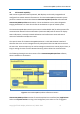
GammaCompMD QA Client User Manual 13. MD215MG EDID Serial Number Update Tool 13.1. Overview The NEC model MD215MG is supported by GammaCompMD QA Client. All communication is performed via DCC/CI commands over a USB cable. Multiple MD215MG displays which are connected to the same system must be calibrated sequentially. The serial number of each unit is required to identify a MD215MG display.
GammaCompMD QA Client User Manual 13.2. Hardware Setup Connect one or more MD215MG display(s) to the workstation, using the DVI and USB cables provided. USB cable MD215MG DVI cable GammaCompMD QA Client Figure 141: Connections 13.3. Software Installation This tool is included in the GammaCompMD QA Client software package. GammaCompMD QA Client must be installed prior to use. 13.4.
GammaCompMD QA Client User Manual Figure 142: Detecting Connected Display(s) The message Start updating serial number will appear after the display has been successfully detected (Figure 143). Click OK to update the serial number. Figure 143: Serial Number Update Tool Figure 144: Updating Serial Numbers Serial numbers will be updated for all displays currently connected. A dialog box will be displayed after a successful update (Figure 145).
GammaCompMD QA Client User Manual Update of N display(s) successful, Click OK when complete. The value N will show the number of displays currently connected. (N=1 to 8) 13.6. Calibration The model NEC MD215MG is now ready to be calibrated using GammaCompMD QA. Calibration can begin after GammaCompMD QA software has been started and the MD215MG display(s) have been identified. 13.7. Troubleshooting No Error Message, Event 1 Action Unable to detect MD215MG display. Reconnect the display and try again.
GammaCompMD QA Client User Manual 14. Notes 14.1. Restrictions If you are using GammaCompMD QA Client in multiple accounts, do not use the [Windows] [Switch User] function, but either [Log off] or restart your computer to change the login account. 14.2. Copyright Information This product includes the following software: QT 4.7 PostgreSQL 8.4.
GammaCompMD QA Client User Manual 15. Appendix 1280x1024 --- Secondary 250 cd/m2 0.8 cd/m2 Native EA224WMi IPS 0.248 1920x1080 --- Secondary 250 cd/m2 0.8 cd/m2 Native EA234WMi IPS 0.265 1920x1080 --- Secondary 250 cd/m2 0.8 cd/m2 Native EA244WMi IPS 0.270 1920x1200 --- Secondary 250 cd/m2 0.8 cd/m2 Native Secondary 250 cd/m2 0.8 cd/m2 Native Black Level Default White Point Default ACR Default Rank 0.
GammaCompMD QA Client User Manual LCD5220 PVA 0.600 1920x1080 --- Secondary 250 cd/m2 0.8 cd/m2 Native LCD6520L PVA 0.744 1920x1080 --- Secondary 250 cd/m2 0.8 cd/m2 Native LCD6520P PVA 0.744 1920x1080 --- Secondary 250 cd/m2 0.8 cd/m2 Native LCDX461HB PVA 0.746 1366x768 --- Secondary 250 cd/m2 0.8 cd/m2 Native LCDX461UN PVA 0.746 1366x768 --- Secondary 250 cd/m2 0.8 cd/m2 Native Multeos M40 PVA 0.461 1920x1080 --- Secondary 250 cd/m2 0.
GammaCompMD QA Client User Manual MD301C4 IPS 0.251 2560×1600 MD322C8 IPS 0.182 3840x2160 1280×1600 Diagnostic 350 cd/m2 1.2 cd/m2 Native Secondary 250 cd/m2 0.8 cd/m2 Native 1920x2160 1920x1080 MD205MG IPS 0.156 2048x2560 --- Mammography 420 cd/m2 1.2 cd/m2 MD205MG-1 IPS 0.156 2048x2560 --- Mammography 420 cd/m2 1.2 cd/m2 MD215MG IPS 0.165 2048x2560 --- Mammography 420 cd/m2 1.2 cd/m2 MD211G5 IPS 0.165 2048x2560 --- Mammography 420 cd/m2 1.
GammaCompMD QA Client User Manual AVC2N2N IPS 0.270 1200x1600 --- Diagnostic 350 cd/m2 1.2 cd/m2 Native AVC2N3N IPS 0.270 1920x1200 960x1200 Diagnostic 350 cd/m2 1.2 cd/m2 Native AVC3N0N IPS 0.212 1536x2048 --- Diagnostic 350 cd/m2 1.2 cd/m2 Native AVC3N1N IPS 0.212 1536x2048 --- Diagnostic 350 cd/m2 1.2 cd/m2 Native AVC4N0N IPS 0.251 2560x1600 --- Secondary 350 cd/m2 1.2 cd/m2 Native AVC4N1N IPS 0.251 2560x1600 1280×1600 Diagnostic 350 cd/m2 1.
GammaCompMD QA Client User Manual 15.2. Saved Settings for Upgrade Section Setting Saved for Issue upgrade? Display Overview Display Models Saved When there is a model previous GammaCompMD QA wasn't supporting, the information is saved. Display Overview Display Order Saved If the composition is changed, warning is indicated.
GammaCompMD QA Client User Manual Administrator Network Execution Saved Setup Administrator Backup Schedule Saved Setup Administrator Access Rights for Saved Quality Assurance Administrator User Password Saved Setup Administrator Startup User Level Saved Administrator White & Black Saved Luminance Measurement Reports Administrator Uniformity Test Saved Reports Copyright © NEC Display Solutions Ltd.
GammaCompMD QA Client User Manual 15.3. How important is Reference Calibration? Whenever any parameter in the Calibration Setup menu was changed and the display configuration includes displays with integrated front sensors or retractable sensors, a message pops up, as shown in as shown in Figure 146.
GammaCompMD QA Client User Manual Regular re-adjustment of integrated front sensors or retractable sensors It is a common physical phenomenon that all light sensors lose their sensitivity over time when a light source emitting some ultraviolet light is measured permanently. The backlights of LCD Displays contain some small part of ultraviolet light, causing the plastic cover material of such a sensor to deteriorate. The sensitivity of the sensor will be reduced over time.
GammaCompMD QA Client User Manual For your installation notes: Copyright © NEC Display Solutions Ltd.
GammaCompMD QA Client User Manual Copyright © NEC Display Solutions Ltd.