GT6000/GT5000 LCD Projector User’s Manual
Important Information Precautions Please read this manual carefully before using your NEC GT6000/ GT5000 Projector and keep the manual handy for future reference. Your serial number is located on the bottom of your GT6000/ GT5000. Record it here: If you are a user of the GT6000R, read the supplied document which describes the differences from the GT6000.
Important Information • The projector must be operated with two lamp housings installed regardless of whether or not the lamp is active. Failure to do so may degrade the performance of the projector such as screen flicker or loss of lamp life. If one lamp has reached the end of its usable life, replace it with a new one as soon as possible. Power Supply 1. The projector is designed to operate on a power supply of 100120 or 200-240 V 50/60 Hz AC.
Table of Contents 1. Introduction 7. Setting Up for Double Stacking in Link Mode z What's in the Box? .................................................................... 1-2 x Introduction to the Projector ................................................... 1-3 c Getting to Know Your Projector ............................................... 1-4 Attaching the lens hood cap to the lens hood with the supplied string and rivet ............................................................................
1 Introduction ○ ○ ○ ○ ○ ○ ○ ○ ○ ○ ○ ○ ○ ○ ○ ○ ○ ○ ○ ○ ○ ○ ○ ○ ○ ○ ○ ○ ○ ○ ○ ○ ○ ○ ○ ○ ○ ○ ○ ○ z What's in the Box? .................................................... 1-2 x Introduction to the Projector ..................................... 1-3 c Getting to Know Your Projector ................................. 1-4 Attaching the lens hood cap to the lens hood with the supplied string and rivet . 1-6 Carrying the Projector ....................................................................................
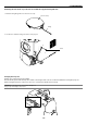
1. Introduction z What's in the Box? Make sure your box contains everything listed. If any pieces are missing, contact your dealer. Please save the original box and packing materials if you ever need to ship your Projector. NOTE: Lenses are optional. Order lenses from your NEC dealer.
1. Introduction x Introduction to the Projector This chapter introduces you to the GT6000/GT5000 high end fixed installation projector and describes key features and controls. Congratulations on Your Purchase of the GT6000/GT5000 projector The GT6000/GT5000 is our most sophisticated three panel, dual lamp XGA LCD projector.
1.
1.
1. Introduction Attaching the lens hood cap to the lens hood with the supplied string and rivet 1. Thread the string through the hole on the lens hood cap. Lens hood cap String Rivet AUDIO R/Cr AUDIO G/Y B/Cb H/HV R L/MONO R L/MONO V S-VIDEO VIDEO RGB OUT R RGB 2 L/MONO AUDIO OUT R RGB 1 L/MONO OPTION 1 DVI OPTION 2 2. Use the rivet to attach the string to the bottom of the projector. Carrying the Projector Always carry your projector by the handle.
1. Introduction Top Features 14 13 12 10 9 8 11 6 7 MENU UP Z 3D LEFT NT 5 PC CARD 2 LAMP 1 ER LAMP 2 4 A 3D REFORM AUTO ADJUST SELECT DOWN ZOOM PC CARD 1 1. POWER Button (ON / STAND BY)( RIGHT E FOCUS LENS SHIFT L F CAN CE STATUS 3 ON/STAND BY POWER 2 1 7. AUTO ADJUST Button ) Use this button to adjust Position-H/V and Pixel Clock/Phase for an optimal picture. See page 3-6.
1. Introduction DVI AUDIO Input Mini Jack (Stereo Mini) This is where you connect the audio output from your computer when connected to the DVI input. A commercially available audio cable is required. Terminal Panel Features 2 1 AUDIO 3 4. RGB OUT Connector (Mini D-Sub 15 Pin) You can use this connector to loop your computer image to an external monitor from the RGB 1 or 2 input source. 8 5.
1. Introduction 6. SC. TRIGGER Mini Jack When the projector is powered ON the screen trigger output sends a low voltage trigger to the screen controller and the screen will go down. When the projector is powered OFF the screen trigger stops sending a low voltage trigger to the screen controller and the screen will go up.
1. Introduction v Remote Control Features 1. POWER ON Press and hold this button for a minimum of two seconds to turn on the projector when the main power is supplied and the projector is in standby mode or idle mode. 2. POWER OFF Press and hold this button for a minimum of two seconds to turn off the projector. POWER OFF ON 1 2 MENU 5 - BS ADDRESS + 3 ENTER 4 6 7 ADJUST IMAGE PICTURE WHITE BAL. PROJECTOR 9 10 ABC DEF GHI 1 2 3 JKL MNO PQR 4 5 6 STU VWX YZ/ 7 8 9 ,.
1. Introduction 25. MAGNIFY/ZOOM (+/–) Magnify the size of a target portion. While pressing and holding CTL, pressing this button allows you to zoom the lens in and out. 2 E D H R JU D A N E F F O R E W O P B S O - N + M IC BC E W S E U 15. PIXEL Displays the Position/Clock screen to adjust the clock and phase. T N S ES DR ER AD T IM A L. G E 14. HELP Provides online help. M 26. CTL Used in conjunction with other buttons, similar to a shift key on a computer. TU 13.
1. Introduction Remote Control Precautions Operating Range for Wireless Remote Control • The remote control system may not function when direct sunlight or strong illumination strikes the remote control sensor of the main unit, or when there is an obstacle in the path. The infrared signal operates by line-of-sight up to a distance of approximately 7m (20 feet) and a 60 degree angle of the remote sensor.
1. Introduction Using the Remote Control in Wired Operation Connect one end of the supplied remote cable to the REMOTE 2 IN mini jack and the other end to the remote jack on the remote control. NOTE: Do not use this jack for anything other than intended use. Connecting the wired remote control to the SC. TRIGGER Mini Jack causes damage to the remote control.
2 Installation ○ ○ ○ ○ ○ ○ ○ ○ ○ ○ ○ ○ ○ ○ ○ ○ ○ ○ ○ ○ ○ ○ ○ ○ ○ ○ ○ ○ ○ ○ ○ ○ ○ ○ ○ ○ ○ ○ ○ ○ z Setting Up Your Projector .......................................... 2-2 Screen Size and Projection Distance .................................................................. 2-2 x Lens Shift Adjustable Range .................................... 2-4 c Optional Lens Installation ......................................... 2-6 v Making Connections ...............................................
2. Installation This chapter describes how to set up your projector and how to connect video and audio sources. z Setting Up Your Projector Your Projector is simple to set up and use. But before you get started, you must first: 1. Determine the image size 4. Connect the supplied power cable. 2. Set up a screen or select a non-glossy white wall onto which you can project your image. 5. Set up the projector. 3. Install the optional lens to the projector. 7.
2. Installation GT34ZLB (H⳯3.2) - (H⳯4.8) GT20ZL (H⳯2.0) - (H⳯2.6) GT13ZLB (H⳯1.2) - (H⳯1.5) GT06RLB (H⳯0.6) GT10RLB (H⳯1.0) GT12ZLB (H⳯1.2) - (H⳯1.7) GT19ZLB (H⳯1.7) ⳯ (H⳯2.2) GT24ZLB (H⳯2.2) - (H⳯3.2) GT48ZLB (H⳯4.8) - (H⳯7.1) Throw distance For screen sizes between 40" and 500" not indicated on the above table, use formulas below. Projection Distance= Screen Width (H) ⳯ Lens Magnification Throw distance for GT06RLB (m/inch) = H ⳯ 0.6 Distance from 0.4m to 1.5m / 17.5" to 57.
2. Installation x Lens Shift Adjustable Range The top right diagram shows the location of the image position in the lens. The lens can be shifted within the shaded area as shown using the normal projection position as a starting point. Maximum Possible Range for GT12ZLB/GT20ZL/GT48ZLB: Up: Down: Right: Left: 0.5 V 0.5 V 0.32 H 0.32 H (V: height of projected image) (H: width of projected image) NOTE: Lens shift is not available on the GT06RLB and the GT10RLB rear lens.
2. Installation Lens Shift Adjustable Range (continued) The top right diagram shows the location of the image position in the lens. The lens can be shifted within the shaded area as shown using the normal projection position as a starting point. Maximum Possible Range for GT13ZLB/GT19ZLB/GT24ZLB/GT34ZLB: Values in parentheses for GT13ZLB. Up: 0.39V (0.32V) (V: height of projected image) Down: 0.39V (0.32V) Right: 0.24H (0.19H) (H: height of projected image) Left: 0.24H (0.
2. Installation c Optional Lens Installation This section describes how to install the lens. See page 2-8 for installing the GT12ZLB lens and page 2-10 for the GT06RLB lens. Before installation * Determine the optional lens to be used to obtain a desired projection distance.
2. Installation 3. Mount the lens unit on the projector and connect the extension cable attached to the projector. q Remove the lens cap from the rear end of the lens unit. NOTE: Leave the front lens cap for protection while mounting the lens unit. w Insert the lens unit so that the 4 screws on the lens unit are properly lined up with the 4 holes on the lens mount. CAUTION: There is a lens shift detection switch for the moving gears of the lens shift motors used to reduce the risk of pinching fingers.
2. Installation For installing the GT12ZLB Preparation: Tools needed for installation: A hexagonal driver is supplied with the optional lens. 1. Remove the lens hood cap and lens hood. q Remove the lens hood cap. w Loosen and remove the 2 screws on the lens hood using the hexagonal driver. e Remove the lens hood by pushing down and pulling the top toward you.
2. Installation 3. Mount the lens unit on the projector and connect the extension cable attached to the projector. q Remove the lens cap from the rear end of the lens unit. NOTE: Leave the front lens cap for protection while mounting the lens unit. w Insert the lens unit so that the 4 screws on the lens unit are properly lined up with the 4 holes on the lens mount. CAUTION: There is a lens shift detection switch for the moving gears of the lens shift motors used to reduce the risk of pinching fingers.
2. Installation For installing the GT06RLB Preparation: Tools needed for installation: A hexagonal driver is supplied with the optional lens. 1. Remove the lens hood cap and lens hood. q Remove the lens hood cap. w Loosen and remove the 2 screws on the lens hood using the hexagonal driver. e Remove the lens hood by pushing down and pulling the top toward you.
2. Installation 3. Mount the lens unit on the projector and connect the extension cable attached to the projector. q Remove the lens cap from the rear end of the lens unit. NOTE: Leave the front lens cap for protection while mounting the lens unit. w Insert the lens unit so that the 4 screws on the lens unit are properly lined up with the 4 holes on the lens mount. NOTE: Make sure that the lens unit is attached with the knobs facing up.
2. Installation r Reattach the front part which was removed on step q above and rotate the knob in clockwise direction to secure it. t Remove the front lens cap from the lens unit. This completes installation. If necessary, put the lens hood cap on the lens hood.
2. Installation v Making Connections NOTE: When using with a notebook PC, be sure to connect between the projector and the notebook PC before turning on the power to the notebook PC. In most cases signal cannot be output from the RGB output unless the notebook PC is turned on after connecting with the projector. * If the screen goes blank while using your remote control, it may be the result of the computer's screen-saver or power management software.
2. Installation To connect SCART output (RGB) 1. Turn off the power to the projector and your video equipment. Before connections: An exclusive SCART adapter (ADP-SC1) and a commercially available SCART cable are required for this connection. 2. Use the NEC ADP-SC1 SCART adapter and a commercially available SCART cable to connect the RGB 2 input of your projector and a SCART output (RGB) of your video equipment. NOTE: • Audio signal is not available for this connection.
2.
2.
2. Installation Connecting to a Network With the LAN connection, you can control the projector over the network using a computer to switch the unit on/off, select the input and others. * To control the projector over the network using a computer, use the Dynamic Image Utility 2.0 contained on the User Supportware CD-ROM or the HTTP Server feature. * With the Image Express Utility 1.0 contained on the supplied User Supportware CD-ROM, you can project your PC screen image to the projector over the network.
2. Installation Connecting the Supplied Power Cable Connect the supplied power cable to the projector. First connect the supplied power cable's three-pin plug to the AC IN of the projector, and then connect the other plug of the supplied power cable in the wall outlet.
3 Projecting an Image (Basic Operation) ○ ○ ○ ○ ○ ○ ○ ○ ○ ○ ○ ○ ○ ○ ○ ○ ○ ○ ○ ○ ○ ○ ○ ○ ○ ○ ○ ○ ○ ○ ○ ○ ○ ○ ○ ○ ○ ○ ○ ○ z Turning on the Projector............................................ 3-2 x Selecting a Source ................................................... 3-3 c Adjusting the Picture Size and Position .................... 3-3 v Correcting the Horizontal and Vertical Keystone Distortion (3D Reform) ................ 3-4 b Optimizing RGB Picture Automatically .....................
3. Projecting an Image This chapter describes how to turn on the projector and to project a picture onto the screen. 2. Press the ENTER button to execute the selection. z Turning on the Projector MENU 3D L NT A 3D REFORM AUTO ADJUST SELECT E NOTE: • When plugging in or unplugging the supplied power cable, make sure that the main power switch is pushed to the off[O] position. Failure to do so may cause damage to the projector.
3. Projecting an Image x Selecting a Source c Adjusting the Picture Size and Position Selecting the computer or video source 1. Turn on the projector 2. Select your type of projector orientation. Desktop front, ceiling rear, desktop rear, and ceiling front. Using the Remote Control POWER OFF Press the Source/Number button (0-9) to select input. ON MENU - BS ADDRESS + ENTER 1 ...... RGB 1 input 2 ...... RGB 2 input ADJUST 3 ...... DVI (DIGITAL) input IMAGE PICTURE WHITE BAL.
3. Projecting an Image (2) Press and hold the CTL and press the ZOOM + or - button to adjust the image size. You can also adjust the image size by using the ZOOM + or - button on the projector cabinet. Preparation (Recommended): Warm up the projector for about 60 minutes. Adjusting the Focus MAGNIFY + + - - FOCUS 1. Practice focusing Use the FOCUS (+) or (-) button on the projector or the remote control to increase or decrease the focus values to verify the accuracy of focusing. 2.
3. Projecting an Image 3. Press the 3D REFORM button on the remote control. The Cornerstone adjustment screen is displayed. The Cornerstone adjustment screen will disappear when you move the USB mouse cursor. When using the remote control or cabinet buttons: 4. Point to one of the remaining 3 corners and left-click on it. 2. Pick up any one of the corners and align the corner of the image with a corner of the screen. Projected image Left-click on the corner. 1.
3. Projecting an Image 8. Use the SELECT 왖왔왗왘 button to select another icon which points in the direction. b Optimizing RGB Picture Automatically Adjusting the Image Using Auto Adjust Optimizing RGB image automatically Press the Auto Adjust button to optimize an RGB image automatically. [Poor picture] MENU Screen 3D L E NT On the Cornerstone adjustment screen, select “Exit” and then “OK”, or press the CANCEL button on the remote control.
3. Projecting an Image m Turning off the Projector To turn off the projector: First press the POWER (ON/STAND BY) button on the projector cabinet or the POWER OFF button on the remote control for a minimum of two seconds. The POWER indicator will glow orange. After the projector turns off, the cooling fans keep operating for 90 seconds (2 minutes in the optional extended life lamp GT60LPS) (Cooling-off time). Second, turn off the Main Power switch. The power indicator will go out.
4 Convenient Features ○ ○ ○ ○ ○ ○ ○ ○ ○ ○ ○ ○ ○ ○ ○ ○ ○ ○ ○ ○ ○ ○ ○ ○ ○ ○ ○ ○ ○ ○ ○ ○ ○ ○ ○ ○ ○ ○ ○ ○ z Turning Off the Image and Sound ............................. 4-2 x Enlarging and Moving a Picture ................................ 4-2 c Getting the On-line Help and Information ................. 4-2 v Using a USB Mouse ................................................. 4-3 b Using a USB HUB Function ...................................... 4-3 n Changing Background Logo ...................................
4. Convenient Features z Turning Off the Image and Sound x Enlarging and Moving a Picture Press the MUTE PICTURE button to turn off the image and sound for a short period of time. Press again to restore the image and sound. You can enlarge the area you want up to 400 percent. To do so: Press the MAGNIFY button. MUTE PICTURE SOUND OSD Press the MUTE SOUND button to turn off the sound for a short period of time. Press again to restore the sound. Enlarge the selected area.
4. Convenient Features v Using the USB Mouse Operate the PC mouse using the USB mouse USB(PC) Using a commercially available USB mouse gives you smooth operation.
4. Convenient Features n Changing Background Logo You can change the default background logo using the PC Card Files feature. NOTE: File size must be 256KB or less. File formats other than JPEG and BMP are not available. 1. From the menu, select [Tools] → [PC Card Files] to display a list of all the files stored in the PC card so that you can select a file you want to use as a background logo.
4. Convenient Features , Lens Memory This function serves to store the adjusted value when using the Shift, Focus, and Zoom buttons of the projector or the remote control. Reference memory: Reference Point ....... Adjusted settings are stored in memory as a reference common to all the input sources. If no setting is stored in Custom Point, the adjusted settings in Reference Point will be applied. Custom memory: Custom Point ........... Adjusted settings are stored in memory for each input signal.
5 Using the Viewer ○ ○ ○ ○ ○ ○ ○ ○ ○ ○ ○ ○ ○ ○ ○ ○ ○ ○ ○ ○ ○ ○ ○ ○ ○ ○ ○ ○ ○ ○ ○ ○ ○ ○ ○ ○ ○ ○ ○ ○ z Making the Most out of the Viewer Function ............. 5-2 x Operating the Viewer Function from the Projector (playback) .................................................................
5. Using the Viewer NOTE: • To use the Viewer, first you need to create presentation materials on your PC using the Dynamic Image Utility 2.0 contained on the supplied NEC Projector User Supportware CD-ROM. For installation, see “6- b Software Installation”. For creating presentation materials, see the Slide show function on the on-line manual of the Dynamic Image Utility 2.0. • Selecting Viewer sets the audio input for DVI input.
5. Using the Viewer x Operating the Viewer Function from the Projector (playback) When the tool bar is not displayed: You can use the 왗 and 왘 button on the cabinet to select folders or slides. This section describes the operation for showing slides of presentation documents created using the Viewer function with the projector. It is also possible to make slides directly from the images projected with the projector. MENU 3D E L NT Projecting slides (Viewer) 1. Insert a PC card into the PC card slot.
5. Using the Viewer If the "Auto Play" option is selected in "Viewer Options" of the menu, any given slide will start to play automatically. You can also specify Auto Play Interval between 5 and 300 seconds. Preparations: Insert the PC card into the card slot. Insert the PC card so that the end with the insertion direction arrow on the top goes in first. * Press the eject button to eject the card. Switching to Slides Directly from Other Input Modes 1.
5. Using the Viewer Deleting Captured Images Using the Delete button on the tool bar for Viewer can delete captured images. Prev Play Next Jump Stop Delete Drive Select Setup View To delete captured images: 1. Select Viewer and display a folder list of captured images. button to select the Capture folder “Cap” in the right bottom of 2. Use the screen. 3. Press the MENU button to display the tool bar. 4.
6 Using the Projector in a Network ○ ○ ○ ○ ○ ○ ○ ○ ○ ○ ○ ○ ○ ○ ○ ○ ○ ○ ○ ○ ○ ○ ○ ○ ○ ○ ○ ○ ○ ○ ○ ○ ○ ○ ○ ○ ○ ○ ○ ○ z End User License Agreement ................................... 6-2 x Introduction ............................................................... 6-3 c Supported Projectors ................................................ 6-4 v Equipment Connections and Settings ...................... 6-5 b Software Installation .................................................
6. Using the Projector in a Network Be sure to read this before installing and using the accompanying software. z END USER LICENSE AGREEMENT PLEASE READ THIS SOFTWARE LICENSE AGREEMENT ("LICENSE") CAREFULLY BEFORE INSTALLING THE SOFTWARE. IT PROVIDES THE TERMS OF THIS LICENSE. WHILE INSTALLING THE SOFTWARE, THIS SOFTWARE LICENSE AGREEMENT WILL BE DISPLAYED. BY CLICKING ON THE "Yes" BUTTON, YOU ARE CONSENTING TO BE BOUND BY THIS AGREEMENT.
6. Using the Projector in a Network x Introduction *1: Please purchase a commercially available PCMCIA Type 2 (ATA specification) flash memory card. Thank you for your purchase of the NEC portable projector (hereafter referred to as "unit" or "projector"). This projector is connected to a personal computer or other equipment and clearly projects text or graphics to a screen. This projector is supplied with convenient software that allows presentations to be made more simply and effectively.
6. Using the Projector in a Network c Supported Projectors The following NEC projectors will be supported: GT6000/GT5000*1, MT1065/MT1060/MT860, LT260/LT240/LT220/LT260K/LT240K/WT600 and VT770*2. *1 The GT6000/GT5000 comes standard with a LAN port (RJ-45). *2 The whole functions of Image Express Utility 1.0 and certain functions of Dynamic Image Utility are not available on the VT770 because the VT770 does not support network connections.
6. Using the Projector in a Network v Equipment Connections and Settings [For Connections with USB Cable] When Using a Network Environment Equipment to Be Prepared • Projector (This unit) What Can Be Accomplished • Personal computer • Using Image Express Utility 1.0, the screen image displayed by the personal computer can be sent to the projector and then projected to a screen. • USB cable (included with the projector) • Using Dynamic Image Utility 2.
6. Using the Projector in a Network b Software Installation Uninstalling NOTE • Windows XP operations will be described in examples given here. • When using Windows 2000, please perform software installation/uninstalling with "Administrators" authority. When using Windows XP, perform with "Computer Administrator" authority. • If you have NEC Projector User Supportware (Dynamic Image Utility 2.0 and Image Express Utility 1.
6. Using the Projector in a Network n Starting/Exiting the Software Display Help Preparation: Please start Viewer PPT Converter 2.0. NOTE: Windows XP operations will be described in examples given here. Dynamic Image Utility 2.0 Start the Software Preparation: Install the software on the personal computer from the supplied CD-ROM. (Page 6-6) The software cannot be started from the supplied CD-ROM. From the [Start] menu click [All Programs] → [NEC Projector User Supportware] → [Dynamic Image Utility 2.0].
6. Using the Projector in a Network m Troubleshooting In this section, the software names have been abbreviated as follows: Dynamic Image Utility 2.0 to DIU 2.0, Viewer PPT Converter 2.0 to PPTC 2.0, and Image Express Utility 1.0 to IEU 1.0. Installation does not complete normally.
6. Using the Projector in a Network Projection to the screen is not possible when using the LAN environment. (DIU 2.0, IEU 1.0) Check Points Countermeasures Have LAN cards (i.e., adapters) been put into both the personal computer and the projector? Put LAN cards (i.e., adapters) into both the personal computer and the projector. Have the LAN settings (for both the personal computer and the projector) been completed? Perform the LAN settings for both the personal computer and the projector.
6. Using the Projector in a Network The projector cannot be found with "General search". (IEU 1.0) Check Points Countermeasures Are the wireless LAN settings appropriate? Are the channel numbers for the personal computer and the projector set to the same number? When WEP (encryption) has been set, has the same value been set for both the personal computer and the projector? Please check the access points, the personal computer setting values and the projector [LAN Mode] setting values.
6. Using the Projector in a Network When used in the LAN environment, the projector cannot be detected. (DIU 2.0, IEU 1.0) Countermeasures Check Points If you have a personal firewall installed on your computer, the personal firewall may not allow for communication with the projector. Try setting the personal firewall to allow for communication with the projector. For procedures for setting the personal firewall, read the on-line help or the user guide included with the personal firewall.
7 Setting Up for Double Stacking in Link Mode ○ ○ ○ ○ ○ ○ ○ ○ ○ ○ ○ ○ ○ ○ ○ ○ ○ ○ ○ ○ ○ ○ ○ ○ ○ ○ ○ ○ ○ ○ ○ ○ ○ ○ ○ ○ ○ ○ ○ ○ z Stacking and Connecting the Projectors .................. 7-2 x Adjusting and Registering Signals to Be Projected ........... 7-5 c Adjusting the Lens Shift, Zoom and Focus to Clearly Display all projected patterns................................ 7-5 v Link Mode Setting ..................................................... 7-5 b List of Menu Items Available in Link Mode...........
7. Setting Up for Double Stacking in Link Mode z Stacking and Connecting the Projectors NOTE: Up to two units can be gravity stacked without external support. In some cases, however, two images will not align on the screen correctly. This will become more apparent when displaying small text and detailed graphics. NOTE: Do not stack both the GT5000 and GT6000 projectors together.
7. Setting Up for Double Stacking in Link Mode Throw Distances for Optional Lenses Master projector Screen center Slave projector Throw Distance Recommended Throw Distances for Double Stack Screen Size Throw Distance (m) (inch) GT12ZLB GT13ZLB GT19ZLB GT20ZL GT24ZLB GT34ZLB GT48ZLB 1.33 1.61 2.03 – 40 – – 0.94 2.03 2.44 3.05 2.92 60 1.43 – – 2.73 3.27 4.07 3.93 6.21 80 1.92 9.47 3.43 4.10 5.09 4.93 100 7.78 11.88 2.40 4.13 4.93 6.11 5.93 120 2.89 9.35 14.29 5.18 6.18 7.63 7.44 11.70 17.91 150 3.62 6.
7. Setting Up for Double Stacking in Link Mode z-3. Hookup z-3-1. Use commercially available RGB signal cables to connect the RGB output of the master projector to the RGB input of the slave projector until all the projectors are connected. z-3-2. Next, using a commercially available, bi-directional RS-232C cable connect the PC CONTROL OUT terminal of the master projector to the PC CONTROL IN terminal of the slave projector until all the projectors are connected. z-3-3.
7. Setting Up for Double Stacking in Link Mode x Adjusting and Registering Signals to Be Projected c Adjusting the Lens Shift, Zoom and Focus to Clearly Display all projected patterns x-1. Display a desired input signal on the master projector. c-1. Display the internal crosshatch test pattern. x-2. Make adjustments to the signal, then save (register) adjustments on the master projector by pressing and holding CTL and pressing ENTRY LIST button on the remote control.
7.
8 Using On-Screen Menu ○ ○ ○ ○ ○ ○ ○ ○ ○ ○ ○ ○ ○ ○ ○ ○ ○ ○ ○ ○ ○ ○ ○ ○ ○ ○ ○ ○ ○ ○ ○ ○ ○ ○ ○ ○ ○ ○ ○ ○ ○ ○ ○ ○ ○ ○ ○ ○ ○ ○ ○ ○ ○ ○ ○ ○ ○ ○ z Basic Menu Operation ............................... 8-2 Projector Options .....................................8-13 x List of Direct Button Combinations ............ 8-3 Menu ...................................................8-13 c Menu tree ................................................... 8-4 Setup ...................................................
8. Using On-Screen Menu z Basic Menu Operation Customizing the Menu Using the Menus The Custom menu can be customized to meet your requirements. Selecting a menu item from the "Custom Menu Edit" list, allows you to custom tailor the menu items to your needs. NOTE: The on-screen menu may not be displayed correctly while interlaced motion video image is projected. 1. Select "Custom Menu Edit" to display the "Custom Menu Edit" screen. 1.
8. Using On-Screen Menu x List of Direct Button Combinations CTL+ Input (1-10) Switches to any selected signal found in the Entry List. To enable this combination, you must first assign specific remote buttons for direct input selection in the Entry Edit window. CTL+ ENTER (While displaying Entry list) Displays the selected signal. CTL+ CANCEL Returns to the previous menu without closing the slidebar or dialog. CTL+ UNDO Clears all menus or adjustment/setting screens.
8. Using On-Screen Menu c Menu tree NOTE: The item appears dimmed on the menu, it is unavailable. Advanced Menu Source Select Adjust (Source) Sound Ref. Adjust Factory Default Projector Options Tools 1. RGB1 2. RGB2 3. DVI(DIGITAL) 4. Video 5. S-Video 6. Viewer 7. LAN 8. Slot 1 9. Slot 2 0.
8. Using On-Screen Menu NOTE: The shaded item indicates the default setting. Advanced Menu Source Select 3D Reform Conerstone Keystone Screen Screen Type 1.25:1(5:4)/1.33:1(4:3)/1.78:1(16:9)/1.85:1/2.35:1 Position Brightness R/G/B, Contrast R/G/B Adjust (Source) Sound Ref. White Balance Ref. Adjust Ref. Color Correction Ref.
8. Using On-Screen Menu Advanced Menu Lamp Settings Source Select Adjust (Source) Sound Link Mode Lamp Mode Lamp Select Interval Lamp Type Settings Ref. Adjust Factory Default Status Projector Options Tools LAN Mode Status Help Test Pattern * When selecting “PC Card”, the “Network Type” and the “WEP” setting screens appear.
8. Using On-Screen Menu Entering Alphanumeric Characters by Using the Menu v Menu Descriptions & Functions Alphabet or numeric characters are used for your IP address or projector name. To enter an IP Address or projector name, use the software keyboard. For using the software keyboard, see page 10-10. Source Select Enables you to select a video source such as a VCR, DVD player, laser disc player, computer or document camera depending on what is connected to your inputs.
8. Using On-Screen Menu Edit .............. Enables you to change source names or assign the direct key. Video Adjust (not available for RGB) Noise Reduction Source Name Enter a signal name. Up to 18 alphanumeric characters can be used. Input Terminal Change the input terminal. RGB1 and RGB2 are available for RGB signal; Video and S-Video are available for composite signal. Direct key You can assign specific remote keys for direct signal input selection.
8. Using On-Screen Menu SweetVision 3D Y/C Separation This option turns on or off the 3 dimension separation feature. NOTE: This feature is available for NTSC3.58 of Video signal only. Picture Management The SweetVision feature provides improvement of contrast using a proprietary detail enhancement technology. NOTE: This feature is not available for 480p, 576p and HDTV signals. Off ............... Turns off the SweetVision feature Low .............. Selects low level Medium .......
8. Using On-Screen Menu Selecting Gamma Correction Mode Use the 왗 or 왘 buttons to choose one mode from three options. Each mode is recommended for : Resolution This allows you to activate or deactivate the Advanced AccuBlend feature. Dynamic ...... For true color reproduction of natural tones Auto ............. Turns on the Advanced AccuBlend feature. The projector automatically reduces or enlarges the current image to fit the full screen. Natural ......... Normal settings Black Detail .
8. Using On-Screen Menu Sync Protection Lens Memory When a VCR, DVD, or some other equipment that supports Copyguard (a copy prevention system) is played back, the screen may be displayed in a curved manner. Adjustments are made in such circumstances. Use the SELECT 왗 or 왘 button to adjust the VD level. This function serves to store or apply the adjusted value when using the Shift, Focus and Zoom buttons on the projector or the remote control. Set Custom Point ...........
8. Using On-Screen Menu Ref. Adjust Using 3D Reform This feature corrects trapezoidal distortion so that the projected image is rectangular. Two options are available for correcting procedures. You can save adjustment settings by using the 3D Reform Save option on Setup (See page 8-16). Cornerstone Position This feature adjusts the vertical position of the image when viewing video with an aspect ratio selected.
8. Using On-Screen Menu Including Entry List: Reference Lens Memory [Ref. Lens Memmory] Also deletes all the signals in the Entry List and returns to the factory preset. NOTE: Locked signals in Entry List cannot be deleted. Current Signal .................... Resets the adjustments for the current signal to the factory preset levels. All the items in "Adjust (Source)" and "Sound" can be reset. NOTE: Locked signals in Entry List cannot be reset.
8. Using On-Screen Menu Selecting Menu Display Time This option allows you to select how long the projector waits after the last touch of a button to turn off the menu. The preset choices are "Manual", "Auto 5 sec", "Auto 15 sec", and "Auto 45 sec". The "Auto 45 sec" is the factory preset. [Page 2] Manual ........ The menu can be turned off manually. Auto 5 sec ... The menu will automatically be turned off in 5 seconds if no buttons are pressed within 5 seconds. Auto 15 sec .
8. Using On-Screen Menu [Page 2] Setup [Page 1] Selecting Projector Orientation [Orientation] This reorients your image for your type of projection. The options are: desktop front projection, ceiling rear projection, desktop rear projection, and ceiling front projection. Selecting a Color or Logo for Background [Background] Use this feature to display a blue/ black screen or logo when no signal is available. The default background is "Blue". You can change the logo screen using the PC Card Files feature.
8. Using On-Screen Menu Selecting Operation Mode [Operation Mode Select] Set the operation mode of the USB mouse connected to the USB port (MOUSE/HUB) on the projector [Page 4] Auto ............. Depending on connection of the USB port (PC) on the projector and a USB port (type A) on your PC, the USB mouse is operated in the following way: * When connecting the projector to your PC The USB mouse connected to the projector can be used as a PC mouse.
8. Using On-Screen Menu Enabling Last Memory [Last Memory] The projector stores the last signal data in memory for each input (RGB1, RGB2, DVI DIGITAL, Video, S-Video and Slot 1/ 2). This feature will reduce switching time between sources. If a commercially available switcher is connected, turning on this feature may cause the image to appear incorrectly. Should this happen, turn this feature off to mute the screen during switching.
8. Using On-Screen Menu Disabling the Cabinet Buttons [Control Panel Key Lock] This option turns on or off the Control Panel Key Lock function. Lamp Type: The lamp type you use and its information are displayed here. The information displayed here are: Light on or off, standard lamp or extended life lamp and remaining hours. NOTE: * This Control Panel Key Lock does not affect the remote control functions.
8. Using On-Screen Menu Status LAN Mode This feature allows you to set various setting items when the projector is used on your network. Consult with your network administrator about these settings. NOTE: • Connect an Ethernet LAN cable to the LAN port (RJ-45) of the projector for network connection. • NEC's optional wireless LAN card is available. For more information on inserting or ejecting a LAN card, see page 5-2. • Either PC Card Slots 1 or 2 can accept LAN card.
8. Using On-Screen Menu Advanced Network Type (required for wireless only) IP Address An IP address can be automatically assigned to this projector by your DHCP server. If your network does not automatically assign IP address, ask your network administrator for an address, and then register it manually. Mode: Select communication method when using wireless LAN. Infrastructure ....................
8. Using On-Screen Menu WEP (for Wireless only) DHCP Select this option whether using the WEP (Wired Equivalent Privacy) key for encryption or not. To use encryption, specify WEP key. Depending on your network environment, acquiring an IP address from a DHCP server may not be possible. Should this happen, consult your network administrator to make changes to the following settings. Disable ........ Will not turn on the encryption feature. Your communications may be monitored by someone. 64bit ..........
8. Using On-Screen Menu Mail Test Mail: Send a test mail to check if your settings are correct. NOTE: If you entered an incorrect address in a test, you may not receive an Alert mail. Should this happen, check if the Recipient's Address is correctly set. NOTE: Unless any one of the "Sender's Address", "SMTP Server's Name" or "Recipient's Address 1-3" is selected, "Test Mail" is not available. NOTE: Be sure to highlight “OK” and press the ENTER button before executing “Test Mail”.
8. Using On-Screen Menu Seamless Switch (GT6000 only) • Speed 1. What Does This Function Do? This function provides a transition effect during source switching. [Before switching] [During switching] Select one of the three switching speeds: Fast, Medium and Slow. The default setting is “Medium”. • Synchronize The default setting is “Off”. [After switching] Auto Selecting "Off" can cause horizontal lines when a moving image is displayed. If you want to delete the lines, select "Auto".
8. Using On-Screen Menu Delete Setting a Password A password can be set for your projector to avoid operation by an unauthorized person. There are two password options: one for menu and the other for logo. When a password is set, doing any one of the following four operations will display the Password input screen. For Menu: * Changing the menu to Advanced * Editing the custom menu To delete your password: 1. Highlight [Delete] and press the ENTER button.
8. Using On-Screen Menu To register a PC card as a protect key. Security The Security function enables you to protect your projector so that the projector will not project a signal unless you enter a keyword. There is also an option to lock the projector by using a registered PC card as a protect key. Once you have registered your PC card as a protect key, you are required to insert the registered PC card into the PC card slot of the projector each time you turn on the projector.
8. Using On-Screen Menu (3) When you attempt to display an image for which security is set while the security function is enabled • Blanks (spaces) cannot be used in the Keyword section. Tools Provides tools for setting On/Off timer, sleep timer, capturing images, displaying files or changing your background logo in a PC Card and drawing. To delete PC card data you registered. Timer 1. Use the SELECT 왖왔 button to select "Delete" and use the SELECT 왗 button to select the list window. 2.
8. Using On-Screen Menu 3. Select “Edit” and press the ENTER button to open the Edit window. Enabling the On or Off Timer 1. To execute the setting, select “Active” . 4. Set the Day, Time (24 hours format), On-Time and Off-Time using the SELECT buttons and the Software keyboard (1 thru 10). 2. Select “OK” and press the ENTER button. NOTE: When one program or more are specified, all the settings are active. NOTE: The settings will be executed in numerical order.
8. Using On-Screen Menu Enabling Sleep Timer Using ChalkBoard The ChalkBoard feature allows you to write and draw messages on a projected image. See page 4-4. NOTE: This feature is available only when using with USB mouse. Help 1. Select your desired time between 30 minutes and 16 hours: Off, 0:30, 1:00, 2:00, 4:00, 8:00, 12:00, 16:00. 2. Select “Set” and press the ENTER button on the remote control. 3. The remaining time starts counting down. Contents 4.
8. Using On-Screen Menu Page 2 Page 2 Filter Usage, Projector Usage, Projector ID Signal Type, Video Type, Sync Type, Interlace, Direct Key Page 3 Projector Information Displays the information for your projector such as lamp usage, filter usage, version number and others. This dialog box has three pages.
9 Maintenance ○ ○ ○ ○ ○ ○ ○ ○ ○ ○ ○ ○ ○ ○ ○ ○ ○ ○ ○ ○ ○ ○ ○ ○ ○ ○ ○ ○ ○ ○ ○ ○ ○ ○ ○ ○ ○ ○ ○ ○ z Replacing the Lamp .................................................. 9-2 x Replacing or Cleaning the Filter ............................... 9-3 c Cleaning the Cabinet and the Lens ..........................
9. Maintenance This chapter describes the simple maintenance procedures you should follow to replace the lamp and the filter, and to clean the filter and the cabinet. 3. Insert a new lamp housing until the lamp housing is plugged into the socket. CAUTION: Do not use a lamp other than the NEC replacement lamp (Standard life lamp: GT60LP or Extended life lamp: GT60LPS). z Replacing the Lamp The projector has two lamps. The lamp replacement procedure applies to both lamps.
9. Maintenance x Replacing or Cleaning the Filter To replace the filter: • Replace both filters at the same time. • Before replacing the filters, remove dust and dirt from the projector cabinet. • The projector contains high-precision parts. Keep out dust and dirt during filter replacement. • Do not wash the filter with water. Water will damage the filter membrane. • Reattach the filter cover correctly. Failure to do so may cause projector malfunction.
9.
10 Appendix ○ ○ ○ ○ ○ ○ ○ ○ ○ ○ ○ ○ ○ ○ ○ ○ ○ ○ ○ ○ ○ ○ ○ ○ ○ ○ ○ ○ ○ ○ ○ ○ ○ ○ ○ ○ ○ ○ ○ ○ z USB Memory Device or USB Memory Card Reader Support .... 10-2 x Troubleshooting ...................................................... 10-3 c Specifications ......................................................... 10-5 v Cabinet Dimensions ............................................... 10-7 b Pin Assignments of D-Sub RGB Input Connector .. 10-7 n Compatible Input Signal List ...................................
10. Appendix z USB Memory Device or USB Memory Card Reader Support The projector is compatible with either a USB memory device or USB memory card reader which supports the viewer and security features. • To use a USB memory device or USB memory card reader, connect the device to the USB port (type A). • Select one of the Drive icons in the Viewer toolbar, Capture toolbar and PC Card File setting screen. Up to four drives can be accepted.
10. Appendix x Troubleshooting This section helps you resolve problems you may encounter while setting up or using the projector. Power Indicator Indicator Condition Blinking light Off Green blinking Orange blinking Steady light Projector Condition 0.5 sec ON, 0.5 sec OFF 2.5 sec ON, 0.5 sec OFF 0.5 sec ON, 0.5 sec OFF 2.5 sec ON, 0.5 sec OFF Green Orange Note The main power is off – The projector is getting ready to turn on. Wait for a moment. Off Timer or Sleep Timer is active.
10. Appendix Common Problems & Solutions Problem Check These Items Does not turn on • Check that the power cable is plugged in and that the main power switch on the projector is on. See pages 19 and 2-11. • Ensure that the lens hood or the lamp cover is installed correctly. See pages 1-4 and 9-2. • Check to see if the projector has overheated or the lamp has reached the end of its usable life.
10. Appendix If there is no picture, or the picture is not displayed correctly. • Power on process for the projector and the PC. Be sure to connect the RGB cable between the projector and the computer before turning on the computer. There are some notebook PCs, which do not output signal unless there is a projector or monitor connected first. NOTE: You can check the horizontal frequency of the current signal in the projector’s menu under Information.
10. Appendix c Specifications This section provides technical information about the GT6000/GT5000 Projector’s performance. Model Number Optical LCD Panel Lamp Lamp Life Lens Options Lens Shift Image Size Projection Distance Electrical Input Connections Output Connections Other Input/Output Input Compatibility Sychronization Range Video Bandwidth Color Reproduction Horizontal Resolution GT6000/GT5000 1.
10. Appendix Built-in Speakers Power Requirement Input Current Power Consumption (2 lamps) Mechanical Dimensions Net Weight Environment Regulations 5W⳯2 100 - 120VAC / 200 - 240 VAC, 50 / 60 Hz 8.0 A (100 - 120 VAC) / 4.0A (200 - 240 VAC) 800W (Lamp Normal mode) 660W (Lamp Eco mode) 1W (Standby) 20.4" (W)⳯9.5" (H)⳯21.6" (D) / 518 mm (W)⳯242 mm (H)⳯548 mm (D) (not including protrusions) 40.6 lbs / 18.
10. Appendix v Cabinet Dimensions PC CARD 1 ZOOM F PC CARD 2 LAMP 1 LENS SHIFT LAMP 2 NT DOWN LEFT E FOCUS RIGHT ER STATUS POWER L CE CAN ON/STAND BY SELECT 3D REFORM AUTO ADJUST 3D Z A UP 548 (21.6) MENU 2 (0.08) 259 (10.2) 518 (20.4) 6 (0.2) Lens center AUDIO RGB 1 AUDIO OUT 225 (8.9) SLOT 1 242 (9.
10.
10. Appendix m REMOTE 1 Connector 5 4 3 2 1 10 9 8 7 6 15 14 13 12 11 This connector is used for a third party external control device. Pin No.
10. Appendix , PC Control Codes and Cable Connection .
10. Appendix ⁄0 Operation Using an HTTP Browser Structure of the HTTP Server Overview The use of HTTP server functions will allow control of the projector from a web browser without the installation of special software. Please be sure to use “Microsoft Internet Explorer 4.x” or a higher version for the web browser. (This device uses “JavaScript” and “Cookies” and the browser should be set to accept these functions. The setting method will vary depending on the version of browser.
10. Appendix Source Select: This switches the input connector of the projector. RGB1 ...................... Switches to the RGB 1 connector. RGB2 ...................... Switches to the RGB 2 connector. DVI(DIGITAL) ........... Switches to the DVI connector. Video ....................... Switches to the Video connector. S-Video ................... Switches to the S-Video connector. Viewer ..................... Switches to the Viewer. LAN ......................... Switches to a LAN signal. Slot 1-1 ..........