
Operation Manual


2-11
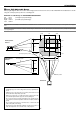
IN
O
U
T
R
E
M
O
T
E
2
A
C
I
N
A
U
DIO
A
U
D
I
O
O
U
T
R
R
/C
r
G/Y
B
/Cb
V
H
/
H
V
R
L
/
M
O
N
O
R
L
/
M
O
N
O
R
L
/
M
O
N
O
L
/
M
O
N
O
D
VI
R
G
B
O
U
T
R
GB 1
RG
B 2
VID
EO
S-VIDEO
A
U
DIO
S
L
O
T
1
S
L
O
T
2
3
IN
O
U
T
R
EM
O
TE
2
A
C IN
A
U
D
IO
A
U
DIO
O
U
T
R
R
/C
r
G
/Y
B
/C
b
V
H
/H
V
R
L
/M
O
N
O
R
L
/
M
O
N
O
R
L
/M
O
N
O
L
/
M
O
N
O
DVI
R
G
B
O
U
T
RGB 1
RGB 2
VIDEO
S-VIDEO
A
U
D
IO
SL
O
T
1
S
L
O
T 2
2
1
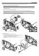
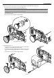
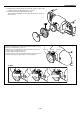
4. Reinstall the lens hood.
q Rotate the knob on the front part of the lens unit in anticlockwise
direction to loosen and remove the front part.
w Insert the lens hood so that the grooves on the 4 corners of the
lens hood are properly lined up with the 4 catches on the projec-
tor.
e Secure the 2 screws using the hexagonal driver.
Lens shift defection switch
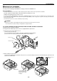
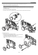
2. Installation
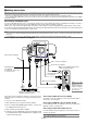
3. Mount the lens unit on the projector and connect the extension cable attached to the projector.
q Remove the lens cap from the rear end of the lens unit.
NOTE: Leave the front lens cap for protection while mounting the lens unit.
w Insert the lens unit so that the 4 screws on the lens unit are properly lined up with the 4 holes on the lens mount.
NOTE: Make sure that the lens unit is attached with the knobs facing up.
CAUTION: There is a lens shift detection switch for the moving gears of the lens shift motors used to reduce the risk of pinching fingers.
Do not defeat this feature.
e Secure the 4 screws using the hexagonal driver.
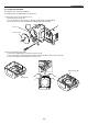
PC CONTROL
IN
IN
OUT
OUT
SC TRIGGER
REMOTE 2
REMOTE 1
LAN
AC IN
USB
(
M
O
U
S
E
/H
U
B
)
USB
(
PC
)
PC CARD
1
2
A
U
D
IO
AUDIO OUT
R
R
/C
r
G
/Y
B
/C
b
V
H/HV
R
L/MONO
R
L/MONO
R
L/MONO
L/MONO
DVI
RGB OUT
RGB 1
RGB 2
VIDEO
S-VIDEO
A
U
D
IO
SLOT 1
SLOT 2
1
PC CONTROL
IN
OUT
SC TRIGGER
USB
(
MOUSE/HUB
)
USB
(
PC
)
PC CAR
D
AUDIO
AUDIO OUT
R
R/Cr
G/Y
B/Cb
V
H/HV
R
L/MONO
R
L/MONO
R
L/MONO
L/MONO
DVI
RGB OUT
RGB 1
RGB 2
VIDEO
S-VIDEO
AUDIO
SLOT 1 SLOT 2
2
3