Entertainment Projector HT510/HT410 User’s Manual English Deutsch Français Italiano Español Svenska
IMPORTANT INFORMATION IMPORTANT INFORMATION Safety Cautions Precautions Please read this manual carefully before using your NEC HT510/HT410 Projector and keep the manual handy for future reference. Your serial number is located on the bottom of your projector. Record it here: CAUTION To turn off main power, be sure to remove the plug from power outlet. The power outlet socket should be installed as near to the equipment as possible, and should be easily accessible.
IMPORTANT INFORMATION RF Interference WARNING The Federal Communications Commission does not allow any modifications or changes to the unit EXCEPT those specified by NEC Solutions (America), Inc. in this manual. Failure to comply with this government regulation could void your right to operate this equipment. This equipment has been tested and found to comply with the limits for a Class B digital device, pursuant to Part 15 of the FCC Rules.
IMPORTANT INFORMATION Fire and Shock Precautions 1. Ensure that there is sufficient ventilation and that vents are unobstructed to prevent the build-up of heat inside your projector. Allow at least 4 inches (10 cm) of space between your projector and a wall. 2. Prevent foreign objects such as paper clips and bits of paper from falling into your projector. Do not attempt to retrieve any objects that might fall into your projector.
IMPORTANT INFORMATION Lamp Replacement • To replace the lamp, follow all instructions provided on page E-45. • Be sure to replace the lamp when the message "The lamp has reached the end of its usable life. Please replace the lamp." appears. If you continue to use the lamp after the lamp has reached the end of its usable life, the lamp bulb may shatter, and pieces of glass may be scattered in the lamp case. Do not touch them as the pieces of glass may cause injury.
TABLE OF CONTENTS TABLE OF CONTENTS IMPORTANT INFORMATION ................................................................................................... E-i Safety Cautions ................................................................................................................................................................................................... E-i What’s in the Box? ..................................................................................................................
TABLE OF CONTENTS Information ................................................................................................................................................................................................... Page 1/2/3 ................................................................................................................................................................................................ Reset ...........................................................................
1. INTRODUCTION 1. INTRODUCTION Introduction to the Projector This section introduces you to your new NEC HT510/HT410 home entertainment Projector and describes its features and controls. Congratulations on Your Purchase of The HT510/HT410 Entertainment Projector The HT510/HT410 is a sophisticated single chip DLP™ projector designed with the enhanced video requirements for the home entertainment user.
1. INTRODUCTION About this user's manual The fastest way to get started is to take your time and do everything right the first time. Take a few minutes now to review the user's manual. This may save you time later on. At the beginning of each section of the manual you'll find an overview. If the section doesn't apply, you can skip it. • Digital Light Processing and DLP are trademarks of Texas Instruments. • IBM is a trademark or registered trademark of International Business Machines Corporation.
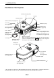
1. INTRODUCTION Part Names of the Projector Controls (See page E-4) Speaker Ventilation (inlet) Remote Sensor (See page E-9) SELE CT Focus ring (See page E-26) AU AD TO J.
1. INTRODUCTION Top Features 5 7 8 4 LAMP 3 2 STATUS POWER SELECT SOURCE ON/STAND BY AUTO ADJ. 1 6 9 10 1. ON/STAND BY button ( ) Use this button to turn the power on and off when the main power is supplied and the projector is in standby mode. To turn on the projector, press and hold this button for a minimum of two seconds. To turn off the projector, press this button twice. 2.
1. INTRODUCTION Terminal Panel Features 7 1 3 Y 4 6 S-VIDEO IN Cb/Pb L PC CONTROL COMPUTER IN AUDIO IN 2 Cr/Pr COMPONENT IN VIDEO IN R AUDIO IN 5 1. COMPUTER IN / Component Input Connector (Mini D-Sub 15 Pin) Connect your computer or other analog RGB equipment such as IBM compatible or Macintosh computers. Use the supplied RGB/VGA cable to connect to your computer.
1. INTRODUCTION Part Names of the Remote Control 1 3 OFF POWER ON 2 COMPONENT COMPUTER 4 VIDEO C-VIDEO COMP. 7 AUTO ADJ. 5 S-VIDEO 10 MENU 11 ENTER 13 ASPECT AUTO EXIT NOISE RED. N.R. PIC-MUTE PICTURE OFF TIMER 15 MUTE FREEZE 16 VOLUME KEY STONE TIMER HELP LIGHT 8 6 9 12 14 17 18 19 21 20 22 1. Infrared Transmitter Direct the remote control toward the remote sensor on the projector cabinet. 2.
1. INTRODUCTION 7. COMP. Button (COMPUTER) Press this button to select a video source from computer or component equipment connected to your COMPUTER IN port. 8. AUTO Button (AUTO ADJ.) Use this button to adjust an RGB source for an optimal picture. See page E-27. 9. SELECT 왖왔왗왘 Button 왖왔 : Use these buttons to select the menu of the item you wish to adjust. 왗왘 : Use these buttons to change the level of a selected menu item. 10. MENU Button Displays the menu for various settings and adjustments. 11.
1. INTRODUCTION Battery Installation 1 Press firmly and slide the battery cover off. both old batteries and install new ones 2 Remove (AAA). Ensure that you have the batteries' polarity (+/–) aligned correctly. the cover back over the batteries until it snaps 3 Slip into place. Do not mix different types of batteries or new and old batteries. Remote Control Precautions • Handle the remote control carefully. • If the remote control gets wet, wipe it dry immediately. • Avoid excessive heat and humidity.
1. INTRODUCTION Operating Range for Wireless Remote Control Remote sensor on projector cabinet 30º Remote control 30º 7m/22 feet • The infrared signal operates by line-of-sight up to a distance of about 22 feet/7 m and within a 60-degree angle of the remote sensor on the projector cabinet. • The projector will not respond if there are objects between the remote control and the sensor, or if strong light falls on the sensor.
2. INSTALLATION AND CONNECTIONS 2. INSTALLATION AND CONNECTIONS This section describes how to set up your projector and how to connect video and audio sources. Your projector is simple to set up and use. But before you get started, you must first: 1 Set up a screen and the projector. 2 Connect your video equipment or computer to the projector. See page E-16 to E-19. 3 Connect the supplied power cable. See page E-20.
2. INSTALLATION AND CONNECTIONS Setting Up the Screen and the Projector Selecting a Location The further your projector is from the screen or wall, the larger the image. The minimum size the image can be is approximately 30" (0.76 m) measured diagonally when the projector is roughly 1.2 m/46 inches (HT410) and 1.0 m/40 inches (HT510) from the wall or screen. The largest the image can be is 200" (5.0 m) when the projector is roughly 8.0 m/316 inches (HT410) and 6.
2. INSTALLATION AND CONNECTIONS Throw Distance and Screen Size The following shows the proper relative positions of the projector and screen. Refer to the table to determine the position of installation. Screen Width Distance Chart Screen Diagonal Screen Height Screen center (B) Screen Bottom Lens Center Throw Angle (α) Throw Distance (C) B = Vertical distance between lens center and screen center C = Throw distance α = Throw angle NOTE: Distances may vary +/-5%.
2. INSTALLATION AND CONNECTIONS HT510 Distance Chart Minimum Lens Shift Position Screen Size (16:9) B (min) Diagonal Width Height wide tele inch mm inch mm inch mm inch mm inch mm 30 762 26.1 664 14.7 374 4.1 103.1 4.1 104.0 40 1016 34.9 886 19.6 498 5.4 137.7 5.5 138.5 55 1397 47.9 1218 27.0 685 7.5 189.4 7.5 190.5 60 1524 52.3 1328 29.4 747 8.1 206.6 8.2 207.8 72 1829 62.8 1594 35.3 897 9.8 247.9 9.8 249.4 73 1854 63.6 1616 35.8 909 9.9 251.4 10.0 252.9 80 2032 69.7 1771 39.2 996 10.8 275.5 10.9 277.
2. INSTALLATION AND CONNECTIONS HT410 Distance Chart Minimum Lens Shift Position Screen Size (16:9) B (min) Diagonal Width Height wide tele inch mm inch mm inch mm inch mm inch mm 30 762 26.1 664 14.7 374 4.9 124.1 4.9 124.7 40 1016 34.9 886 19.6 498 6.5 165.5 6.5 166.3 55 1397 47.9 1218 27.0 685 9.0 227.4 9.0 228.6 60 1524 52.3 1328 29.4 747 9.8 248.1 9.8 249.4 72 1829 62.8 1594 35.3 897 11.7 297.7 11.8 299.2 73 1854 63.6 1616 35.8 909 11.9 301.8 11.9 303.4 80 2032 69.7 1771 39.2 996 13.0 330.7 13.1 332.
2. INSTALLATION AND CONNECTIONS Using the Lens Shift Feature • Manual vertical lens shift provides simple vertical image positioning. Rotate the Lens Shift Dial to move the lens up or down. NS LE T IF SH UP Lens shift dial CAUTION: When the lens shift dial gives resistance, it means the lens shift mechanism has reached the minimum or maximum range of vertical shift. Do not turn the lens shift dial beyond this limit as it may damage the lens shift mechanism.
2. INSTALLATION AND CONNECTIONS Making Connections Connecting Your DVD Player COMPONENT IN AUDIO IN Y S-VIDEO IN Cb/Pb L PC CONTROL COMPUTER IN AUDIO IN Cr/Pr COMPONENT IN VIDEO IN R AUDIO IN AC IN Component video RCA⳯3 cable (supplied) Audio cable (not supplied) Audio Equipment DVD player L AUDIO IN L R Y Cb Cr AUDIO OUT COMPONENT OUT R Audio cable (supplied) You can connect your projector to a DVD player with component output or Video output. To do so, simply: 1.
2.
2. INSTALLATION AND CONNECTIONS Connecting Your PC or Macintosh Computer NOTE: When using with a notebook PC, be sure to connect between the projector and the notebook PC before turning on the power to the notebook PC. In most cases signal cannot be output from RGB output unless the notebook PC is turned on after connecting with the projector. * If the screen goes blank while using your remote control, it may be the result of the computer's screen-saver or power management software.
2. INSTALLATION AND CONNECTIONS To connect SCART output Before connections, the supplied exclusive SCART adapter (VIDEO to SCART with audio L/R) and a commercially available SCART cable are required.
2. INSTALLATION AND CONNECTIONS Connecting the Supplied Power Cable Connect the supplied power cable to the projector. First connect the supplied power cable's two-pin plug to the AC IN of the projector, and then connect the other plug of the supplied power cable in the wall outlet. AU AD TO J.
3. PROJECTING AN IMAGE (BASIC OPERATION) 3. PROJECTING AN IMAGE (BASIC OPERATION) This section describes how to turn on the projector and to project a picture onto the screen. Turning on the Projector NOTE: • The projector has two power switches: a main power switch and an ON/STAND BY button. • When plugging in or unplugging the supplied power cable, make sure that the main power switch is pushed to the off (O) position. Failure to do so may cause damage to the projector.
3. PROJECTING AN IMAGE (BASIC OPERATION) Note on Startup screen (Menu Language Select screen) When you first turn on the projector, you will get the Startup screen. This screen gives you the opportunity to select one of the 9 menu languages. To select a menu language, follow these steps: 1. Use the SELECT 왖 or 왔 button to select one of the 9 languages for the menu. Cabinet controls Remote control MENU LAMP STATUS POWER SOURCE SELECT ON/STAND BY AUTO ADJ. ENTER EXIT NOISE RED.
3. PROJECTING AN IMAGE (BASIC OPERATION) Selecting a Source Selecting the computer or video source Using the cabinet buttons LAMP STATUS POWER SOURCE SELECT Press the SOURCE button. ON/STAND BY AUTO ADJ. Press and quickly release the SOURCE button on the projector cabinet to display the Source list. Each time the SOURCE button is pressed, each source name will be highlighted in sequence. Using the Remote Control OFF POWER ON COMPONENT COMPUTER VIDEO C-VIDEO COMP. AUTO ADJ.
3. PROJECTING AN IMAGE (BASIC OPERATION) Move the projector left to center the image horizontally on the screen. Using the Adjustable Rear Foot The adjustable rear foot provides the projector with a horizontal tilt adjustment. If the projector is placed on an uneven surface, keep the projector level by pushing down the left or right rear part of the top cabinet with both hands. NOTE: A spacer is attached to the adjustable rear foot to provide stability.
3. PROJECTING AN IMAGE (BASIC OPERATION) Adjusting the Tilt Foot 1. Lift the front edge of the projector. 1 SELE CT SO UR CE AUTO ADJ. ON/ STA ND BY STA TUS POW ER LAM P DEO S-VI L/mo Cb/P IN no b Y R AUD IO IN O IN VIDE r Cr/PENT IN PON COM PUT ER IN AUD IO IN COM AC IN L TRO CON Adjustable Tilt Foot Lever 2 Adjustable Tilt Foot 2. Push up the Adjustable Tilt Foot Lever on the front side of the projector to extend the adjustable tilt foot (maximum height). 3.
3. PROJECTING AN IMAGE (BASIC OPERATION) Focus Use the Focus ring to obtain the best focus. NOTE: In a ceiling mounted application, the zoom and focus adjustments may cause the projected image to shift down slightly. If this happens, adjust the lens shift again. Correcting the Vertical Keystone Distortion The Keystone correction feature will correct the vertical distortion of a projected image on the screen.
3. PROJECTING AN IMAGE (BASIC OPERATION) Optimizing an RGB Image Automatically Adjusting the Image Using Auto Adjust Optimizing an RGB image automatically Press the AUTO ADJ. button to optimize an RGB image automatically. [Poor picture] Cabinet controls Remote control LAMP STATUS POWER OFF SOURCE SELECT POWER ON COMPONENT COMPUTER VIDEO ON/STAND BY AUTO ADJ. C-VIDEO COMP. AUTO ADJ. S-VIDEO AUTO [Normal picture] Press the AUTO ADJ.
3. PROJECTING AN IMAGE (BASIC OPERATION) Turning off the Projector To turn off the projector: First, press the ON/STAND BY button on the projector cabinet or the POWER OFF button on the remote control. The “Power Off / Are you sure?” message will appear. Cabinet controls Remote control OFF POWER ON COMPONENT COMPUTER LAMP STATUS VIDEO POWER COMP. AUTO ADJ. SELECT SOURCE C-VIDEO S-VIDEO AUTO ON/STAND BY AUTO ADJ.
3. PROJECTING AN IMAGE (BASIC OPERATION) After Use Preparation: Make sure that the projector’s main power is off. 1. Unplug the power cable. 2. Disconnect any other cables. 3. Retract adjustable tilt foot if extended. 4. Cover the lens with the lens cap. 5. Put the projector and its accessories in the supplied soft case.
4. CONVENIENT FEATURES 4. CONVENIENT FEATURES Turning Off the Image and Sound Press the MUTE button to turn off the image and sound for a short period of time. Press again to restore the image and sound. NOISE RED. ASPECT N.R. PICTURE PIC-MUTE OFF TIMER MUTE FREEZE VOLUME KEY STONE TIMER HELP LIGHT Freezing a Picture Press the FREEZE button to freeze a picture. Press again to resume motion. NOISE RED. ASPECT N.R.
4. CONVENIENT FEATURES Turning Off the Projector at the Preset Time (Off Timer) You can use the Off Timer feature to turn off the projector automatically at a preset time. Eight preset times can be selected: Off, 0:30, 1:00, 2:00, 3:00, 4:00, 6:00 and 8:00. Each time the TIMER button on the remote control is pressed, the preset time will change. You can also set the Off Timer using the menu. See page E-38. NOISE RED. ASPECT N.R.
5. USING ON-SCREEN MENU 5. USING ON-SCREEN MENU Using the Menus NOTE: The on-screen menu may not be displayed correctly while interlaced motion video image is projected. 1. Press the MENU button on the remote control or projector cabinet to display the main menu. SOURCE SELECT AUTO ADJ. 2. Press the SELECT GH buttons on the remote control or the projector cabinet to highlight the menu for the item you want to adjust or set. SOURCE Highlight Indicates the selected menu or item. SELECT AUTO ADJ. 3.
5. USING ON-SCREEN MENU 5. Adjusting the level of a selected item or selecting an item. Slide bar Solid triangle Return key symbol SELECT AUTO ADJ. Radio button For Adjusting items (Slide bar) Slide bar ........ Indicates settings or the direction of adjustment. • Use the SELECT 왗왘 buttons to adjust the item. For Selecting items (Solid triangle) Solid triangle .. Indicates further choices are available. A highlighted triangle indicates the item is active. • Use the SELECT 왗왘 buttons to select the item.
5.
5. USING ON-SCREEN MENU Menu Descriptions & Functions Picture You can adjust brightness, contrast, sharpness, color, hue, noise reduction and Telecine. NOTE: When one of Brightness, Contrast, Sharpness, Color or Hue is highlighted, pressing the ENTER button will display its slide bar for adjustment. Brightness ...... Adjusts the brightness level or the black level of the image. Contrast ......... Adjusts the intensity of the image according to the incoming signal (White level of the image). Sharpness ...
5. USING ON-SCREEN MENU Adjusting Color Management [Color Management] This option allows you to adjust neutral tint for yellow, cyan or magenta. There are 5 factory presets optimized for various types of images, you can set user adjustable settings. Hi-Bright ......... Recommended for presentations from a computer. Video ............. Recommended for standard video such as a TV program. Movie ............. Recommended for film based video such as a movie (DVD or HDTV). Graphic ..........
5. USING ON-SCREEN MENU Selecting Aspect Ratio [Aspect Ratio] Aspect Ratio allows you to select the best Aspect mode to display your source image. You can also display the Aspect Ratio window by pressing the ASPECT button on the remote control. (See page E-7). Normal ........... Source is displayed in a 4:3 windowed area with black on the left and right. Full ................. Sources fill the screen horizontally. Zoom ............. Source is stretched vertically. Native .............
5. USING ON-SCREEN MENU Setup Setting Off Timer [Off Timer] You can use the Off Timer feature to turn off the projector automatically at a preset time. Eight preset times can be selected:Off, 0:30, 1:00, 2:00, 3:00, 4:00, 6:00 and 8:00. NOTE: You can also use the TIMER button on the remote control to set the Off Timer. See page E-31. Selecting Lamp Mode [Lamp Mode] This feature enables you to select two brightness modes of the lamp: Normal and Eco modes.
5. USING ON-SCREEN MENU Advanced Preventing the Unauthorized use of the projector [Security] A keyword can be set for your projector to avoid operation by an unauthorized user using the Menu. When a keyword is set, turning on the projector will display the Keyword input screen. Unless the correct keyword is entered, the projector cannot project an image. To enable the Security function: 1. Select [Advanced] → [Security] and press the ENTER button. The Off/On menu will be displayed. 2.
5. USING ON-SCREEN MENU 3. Type in a combination of the four SELECT 왖왔왗왘 buttons and press the ENTER button. NOTE: A keyword must be four to 10 digits in length. The [Confirm Keyword] screen will be displayed. 4 Type in the same combination of SELECT 왖왔왗왘 buttons and press the ENTER button. The confirmation screen will be displayed. 5. Select “Yes” and press the ENTER button. The Security function has been enabled.
5. USING ON-SCREEN MENU To disable the Security function: 1. Select [Advanced] → [Security] and press the ENTER button. The Off/On menu will be displayed. 2. Select “Off” and press the ENTER button. The Keyword confirmation screen will be displayed. 3. Type in your keyword and press the ENTER button. When the correct keyword is entered, the Security function will be disabled. When the Security function is enabled and the projector is turned on, the projector will display a blue background.
5. USING ON-SCREEN MENU NOTE: • The security disable mode is maintained until the main power is turned off (by setting the main power switch to “O” or unplugging the power cable). • If you forget your keyword, contact your dealer. Your dealer will provide you with your keyword in exchange for your request code. Your request code is displayed in the Keyword Confirmation screen. In this example “K992-45L8-JNGJ4XU9-1YAT-EEA2” is a request code.
5. USING ON-SCREEN MENU Information Displays the status of the current signal and lamp usage. This item has three pages. The information included is as follows: [Page 1] Remaining Lamp Time (%)* Lamp Hour Meter (H) Projector Usage (H) * The progress indicator shows the percentage of remaining bulb life. The value informs you of the amount of lamp usage. When the remaining lamp time reaches 0, the Remaining Lamp Time bar indicator changes from 0% to 100 Hours and starts counting down.
5. USING ON-SCREEN MENU Reset Returning to Factory Default [Factory Default] The Factory Default feature allows you to change adjustments and settings to the factory preset for a (all) source (s) except the following: [Current Signal] Resets the adjustments for the current signal to the factory preset levels. All the items in “Picture”, “Adjustment (except “Wall Color”)” and “Image (except “Keystone” and “Keystone Save”)” can be reset.
6. MAINTENANCE 6. MAINTENANCE This section describes the simple maintenance procedures you should follow to replace the lamp and clean the projector cabinet. Replacing the Lamp After your lamp has been operating for 2000 hours (up to 3000 hours in Eco mode) or longer, the lamp indicator in the cabinet will blink red and the message "The lamp has reached the end of its usable life. Please replace the lamp." will appear.
6. MAINTENANCE 1. Loosen the lamp cover screw until the screwdriver goes into a freewheeling condition and remove the lamp cover. The lamp cover screw is not removable. LAM P ST AT US PO WE R LAM ST PO LE NS ON SH SO /ST WE AT P US R T IF SH E D BY SO T C R IF U AN NS LE ON /ST AN D BY U R C AUT ADJ O . E UP UP AUT ADJ O . S E C T C LE E S LE T 1 2 2. Loosen the two screws securing the lamp housing until the screwdriver goes into a freewheeling condition.
6. MAINTENANCE 3. Insert a new lamp housing until the lamp housing is plugged into the socket. Secure it in place with the two screws. Be sure to tighten the screws. NOTE: • Align the lamp housing with the guide rail. Make sure the lamp housing plug goes to the socket correctly. • If both screws are not tightened securely, an image may not be displayed correctly. In this case, apply firm pressure to the portion of asterisk (쏄) in the above drawing to seat the lamp housing into the case.
6. MAINTENANCE Cleaning the Cabinet and the Lens LAM ST PO AN WE AT P US R NS /ST LE ON C T R IF U SH SO D BY E UP AUT ADJ O . SEL ECT AUT ADJ O . S E LE C T ON /ST AN D BY ST AT US PO WE R LA MP S-V L/m Cb IDE R EO O IN ono /Pb Y AU DIO IN IN VID Pr Cr/ ENT IN ON CO CO MP UT ER IN AU DIO MP IN AC CO NTR IN OL 1. Turn off the projector before cleaning. 2. Clean the cabinet periodically with a damp cloth. If heavily soiled, use a mild detergent.
7. TROUBLESHOOTING 7. TROUBLESHOOTING This section helps you resolve problems you may encounter while setting up or using the projector. Power Indicator Indicator Condition Off Blinking light Green Orange Steady light 0.5 sec On, 0.5 sec Off 2.5 sec On, 0.5 sec Off 0.5 sec On, 0.5 sec Off Projector Condition The projector is cooling down. Wait for a moment. The projector is turned on. The projector is in Standby. Green Orange Note The main power is off.
7. TROUBLESHOOTING Common Problems & Solutions Problem Check These Items Does not turn on • Check that the power cable is plugged in and that the power button on the projector cabinet or the remote control is on. See pages E-20 and E-21. • Ensure that the lamp cover or lamp housing is installed correctly. See page E-47. • Check to see if the projector has overheated or the lamp has reached the end of its usable life.
7. TROUBLESHOOTING Problem Check These Items Picture is blurred • Remove the lens cap. • Adjust the focus. See page E-26. • Reposition the projector to improve its angle to the screen. See pages E-23 and E-24. • Ensure that the distance between the projector and screen is within the adjustment range of the lens. See pages E-11 to E-14. • Condensation may form on the lens if the projector is cold, brought into a warm place and is then turned on.
7. TROUBLESHOOTING If there is no picture, or the picture is not displayed correctly. • Power on process for the projector and the PC. Be sure to connect the RGB cable between the projector and the computer before turning on the computer. There are some notebook PCs, which do not output signal unless there is a projector or monitor connected first. NOTE: You can check the horizontal frequency of the current signal in the projector’s menu under Information.
8. SPECIFICATIONS 8. SPECIFICATIONS This section provides technical information about the HT510/HT410 Projector's performance. Model Number HT510/HT410 Optical DMD Resolution Single Chip Digital Micromirror Device (DMD) HT510: 1024⳯576 pixels*1 up to 1080i with scaling technology HT410: 854⳯480 pixels*1 up to 1080i with scaling technology Lens Manual zoom and focus, manual lens shift F2.0 - 2.48 f=19.5 mm - 23.0 mm Lens shift: Vertical 0.
8. SPECIFICATIONS Mechanical Installation Orientation Dimensions Net Weight Environmental Considerations Regulations Desktop/Front, Desktop/Rear, Ceiling/Front, Ceiling/Rear 7.4" (W)⳯4.4" (H)⳯13.3" (D) 187mm (W)⳯113mm (H)⳯337mm (D) (not including protrusions) 6.6 lbs / 3.
3.11"/79.0 4.4"/113.0 7.36"/187.0 2.07"/52.5 0.33"/8.5 UP PC CONTROL LAMP COMPUTER IN SELECT AUDIO IN SOURCE 5.24"/133.2 Y ON/STAND BY AUTO ADJ. E-55 Cr/Pr COMPONENT IN Cb/Pb VIDEO IN S-VIDEO IN AUDIO IN AC IN R L 13.27"/337.0 9. APPENDIX 9.
9. APPENDIX Pin Assignments of COMPUTER IN (D-Sub RGB) Connector Mini D-Sub 15 Pin Connector 11 12 13 14 15 6 7 8 9 10 1 2 3 4 5 Signal Level Video signal : 0.7Vp-p (Analog) Sync signal : TTL level Pin No.
9.
9.
9. APPENDIX Troubleshooting Check List Before contacting your dealer or service personnel, check the following list to be sure repairs are needed also by referring to the “Troubleshooting” section in your user’s manual. This checklist below will help us solve your problem more efficiently. * Print the following pages.
9. APPENDIX In the space below please describe your problem in detail. Information on application and environment where your projector is used Installation environment Projector Model number: Screen size: Serial No.
9. APPENDIX TravelCare Guide TravelCare - a service for international travelers This product is eligible for "TravelCare", NEC's unique international warranty. Please note that TravelCare coverage differs in part from coverage under the warranty included with the product.
9. APPENDIX NOTE: The product can be used overseas with voltages of 100 to 120V and 200 to 240V by using a power cable suited for the standards and power source voltage of the country in which the product is being used. List of TravelCare Outlets This list applies as of April 1, 2004. For the most up-to-date information, please refer to the websites of the service stations in the various countries on the List of TravelCare Outlets or to the NEC website at http://www.nec-pj.com. In Europe NEC Europe, Ltd.
9. APPENDIX In Asia and Middle East NEC Viewtechnology, Ltd. Address: 686-1, Nishioi, Oi-Machi, Ashigarakami-Gun, Kanagawa 258-0017, Japan Telephone: +81 465 85 2369 Fax Line: +81 465 85 2393 Email Address: support_pjweb@nevt.nec.co.jp WEB Address: http://www.nec-pj.com (Regions Covered) Japan* NEC Hong Kong Ltd.
9. APPENDIX Nautilus Hyosung Inc. Address: 7th Floor, Cheongdam Building, 52, Cheongdam-Dong, Kangnam-Ku, Seoul, Korea 135-100 Telephone: +82 2 510 0234 Fax Line: +82 2 540 3584 Email Address: hds-ykc@hyosung.com (Regions Covered) South Korea Lenso Communication Co., Ltd. Address: 292 Lenso House 4, 1st Floor, Srinakarin Road, Huamark, Bangkapi, Bangkok 10240, Thailand Telephone: +66 2 375 2425 Fax Line: +66 2 375 2434 Email Address: pattara@lenso.com WEB Address: http://www.lenso.
9. APPENDIX Date: / / P-1/ , , TO: NEC or NEC's Authorized Service Station: FM: (Company & Name with signature) Dear Sir (s), I would like to apply your TravelCare Service Program based on attached registration and qualification sheet and agree with your following conditions, and also the Service fee will be charged to my credit card account, if I don't return the Loan units within the specified period. I also confirm following information is correct. Regards.
9. APPENDIX Condition of your TravelCare Service Program Enduser is requested to understand following condition of TravelCare Service Program and complete the necessary information on the application sheet. 1. Service Options: There are 3 types of "Service" available. Enduser has to understand following condition and is required to fill in the Application Sheet. 1) Repair and Return: The 'Faulty unit' is sent or collected from the customer.
9. APPENDIX 5. Loan Service Charges and Conditions: Upon acceptance of this NEC Projector, Customer agrees to assume liability for this loan unit. The current cost of use of this loan unit is $200.00 USD for 12 calendar days. If Customer does not return the unit within the 12 calendar days, Customer will be charged the next highest cost up to and including the full list price to Credit Cards, which price will be informed by NEC Authorized Service Stations.